























This video explains how to dissipate heat from surface mount power devices to an external case using thermal vias and seal pads, by creating a thermal path through the PCB board with multiple vias in parallel to transfer heat from the top side to the bottom side, where a heat spreader bar contacts the case; the thermal design follows an electrical analogy where power equals current, thermal resistance equals electrical resistance (in °C/W), and temperature equals voltage, allowing engineers to calculate temperature rises across each component in the thermal path.
SMD Heatsink Design: Thermal Vias & PCB Case Cooling
Added:Fundamentals of heat transfer theory, specifically thermal conduction through solid materials and the thermal equivalent of Ohm's Law.
Basic PCB design and manufacturing concepts, including multi-layer stackups, copper planes, and the function of standard vias.
Principles of electrical power dissipation, understanding how active SMD components like linear regulators and MOSFETs generate heat.
The concept of thermal resistance (Rth), including junction-to-case (Rjc) and case-to-ambient (Rca) parameters found in component datasheets.
Thermal simulation and modeling using Finite Element Analysis (FEA) software to predict heat distribution and identify PCB hot spots.
Selection and optimization of Thermal Interface Materials (TIMs), such as thermal gap pads, phase-change materials, and thermal grease.
Advanced thermal management solutions, including the integration of heat pipes, vapor chambers, and active cooling elements like fans or thermoelectric coolers.
Designing for reliability and standards compliance, such as IPC-2152 (current-carrying capacity) and thermal cycling testing in environmental chambers.
100.3K views2.4Klikes22:42Original Release: 2015-05-15
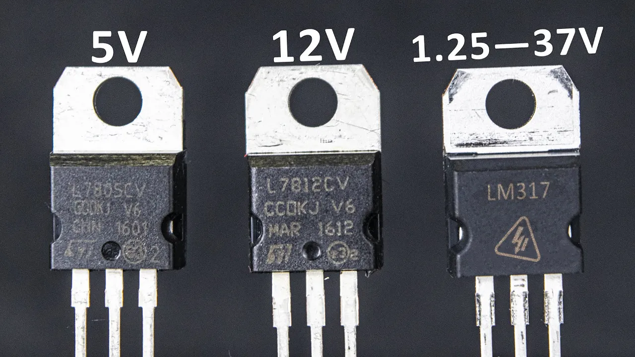
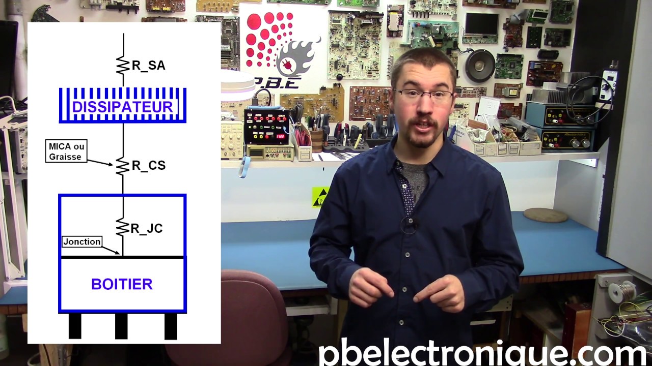
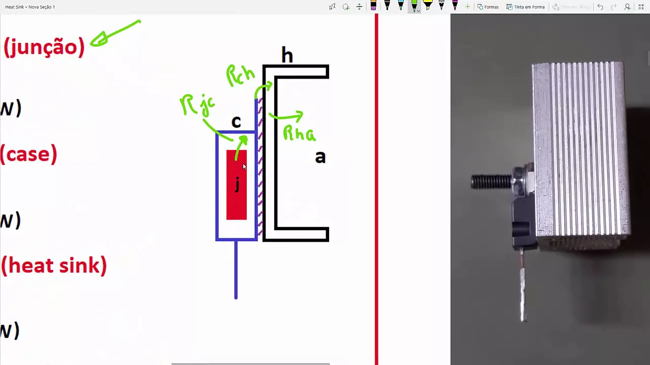
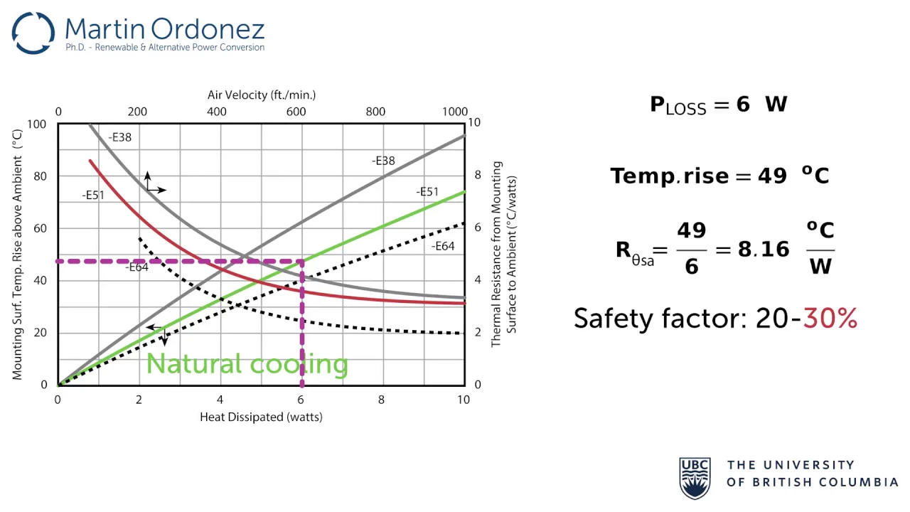
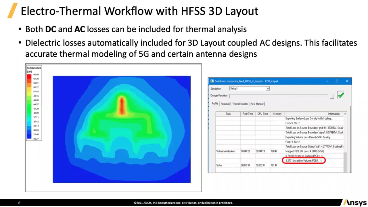
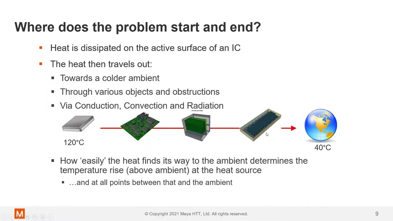
hi back in video 644 which I'll link in down below if you haven't seen it I showed these uh project cases and how you can do front panels and things like that but I also mentioned about how you can get heat out from a regulator in these things now these are a split case like this and I won't go over the whole thing but I basically talked about if you had say a to220 package like that mounted on your board you could actually flip it upside down like that bend the leads in uh the opposite direction to what you would normally bend them for for a through hole package and if you happen to have the right size case which this one is then you can see that it just touches the bottom of there there's enough room to put in an insulating seill pad in there to uh isolate your regulator tab from the case and you can dissipate the power from your regulator or your power transistor or whatever it is into your case and you can effectively use your case as a big heat signal or I mentioned also how you could dissipate heat internal as well with just a regular heat sink like freestanding like that or you know it might be a flatter one like that provided that um it didn't touch the top of your case for example so if you wanted to keep your the uh tab of your voltage regulator or power transistor electrically isolated from the case which is usually the case no pun intend uh usually what you want then well you can do that but the problem with internal heat sinks is that uh usually you're going to have a seal case like this it's generally not going to have a fan on it so all that heat can build up inside and especially if you're using say a battery powered product uh you know you don't want your batteries inside to get hot and things like that so you know really it's not a great thing so dissipating the heat out to your case can be a fairly decent option so I showed how to do that with a to220 but what if you wanted to use a surface mount package like a dpack uh there are lots of advantages to these they could be more readily available they could be cheaper you know through hole is not gone the way of the dodo yet but uh you know generally uh you might have a lot more availability in these modern uh surface mount packages like this dpack or something else and of course you can pick and place them they're brilliant for Pick and placing and uh uh so that you don't have to have the extra step the manual step of having to uh manually you know bend the leads on your uh Power transistor or your regulator and do that you need a you know you need a human to sit there and actually do that sort of thing and then hand solder the thing in that's really annoying but how do you get the heat out of these surface mount parts to the case yeah you can come along and still use your internal heat sink like that you can get like surface mount Heat sinks that also work with pick and place machines they come along boom and they place them down provided that they aren't you know a huge amount of mass otherwise they tend to fall off if it was a big heavy thing like this relatively then you know it' typically fall off the head of the pick and place machine it wouldn't have enough suction to you know pick it up and then bring it over and dump it down but you can get surface mount heat things like that which sit uh which can be pick and placed and then Reflow solded but once again you got all the heat being dissipated in your case cuz you'd have the end on it here and there'd be no forced air uh through the thing cuz you wouldn't you know you generally wouldn't have a fan on something this small so it's not too hard with to220 packages like that uh for example especially if you got the right height case which this one is and you can sort of you know it sort of you got to have Force down there so you might have to screw it or something like that um but still you can you know fair not too without too much trouble get the heat out of that case it's a little bit un professional and messy and a bit sort of like cheap product uh type so it's it's a bit more professional to do it better with surface mount parts and have a proper solution that I'm going to show now of course you could actually flip your board upside down like this you could have your parts mounted on the bottom side like that but then of course you got a double-sided uh load for example you can have all your parts on the bottom and put your uh board on the upper half of the case um either way you do it but you can't sort of flip you can't do the same trick and flip this one over like that it and get the heat out that way it just doesn't work and you can't uh wedge the plastic case of that uh transistor up against here because that it's just way too much thermal resistance you got to have metal to metal contact to get all that heat out that plastic is just going to be horribly horribly inefficient so how do you get your heat out of your little surface mount power transistors or Regulators to the case of your product well it's a good question and there's probably you know a few solutions to this now one solution might be of course a surface mount uh heat sink like that internally and which actually came up to the top of your case or the underside depends on which way you want to uh mount it and then you can actually put screws there and get the heat through and well that's fine and dandy but how do you electrically isolate your tab so for transistors like this that tab on the end there and bottom that gets Reflow solder down to the board it's going to be the collector of the transistor take a look at the data sheet here so you don't want your collector of your transistor connected to your case that could really ruin your day it could short out um something else cuz you might have the collector uh for example connected you know it's not going to be ground now of course if we had a uh like a 7805 voltage regulator for example like we do here this one is then this tab is actually connected to the middle pin which is actually ground and okay if you want to connect your ground if you do want to ground your case then that's fine you can just put your screw in there and you don't need any insulating washer in there so in probably the majority of cases you want to isolate your tab of your regulator or your transistor from the case so you've got to have some sort of insulating material microw washer or a um seal pad or something like that you could have multiple devices you want to isolate them from each other as well cuz they're generally not going to be electrically connected so this is how I would uh probably do it as a first past now I've had David 2 mock up a little animation in solid works here and you can see isn't it quite neat and we've got our power transistors over here or both electrically isolator like that you can see that they've got both different islands of copper so that keeps them all separate so you can have as many isolated devices as you want and you can see that I've got what are called thermal vas I'll go over these in a second either side of the each power transistor there and they are what transfer heat back from the top side of the board cuz we're using topside component load here through to the bottom side of the board where we can actually get a heat uh spreader bar or a heat transfer bar to the case so at this stage it pays to actually go to the Whiteboard so please excuse the crudity of this model didn't have time to build it to scale or to paint it not as good as David 2's 3D model but I've redrawn it here now you may be thinking Dave I think you've shorted out these two power transistors because if we've got this uh red metal bar in here like this and we've got these vs the electric the tab of the power transistor here is connected to our big copper uh plane there with all these thermal vas going through the bottom side now a thermal vea is just another name for a regular via except it's not used to carry current although it can still do that of course it's just just a regular copper via through the board from the top side of the board to the bottom side of the board but in the case of a thermala it's designed to actually transfer heat energy from the top side of the board to the bottom side of the board so anyway so we've got a duplicate pad on the bottom side of the board with all these vs it's exposed copper hasn't got any solder mask over it as you saw in the 3D model so that's going to make contact to our metal bar down the bottom here and it's going to make contact to the metal bar over here one we've just shorted out our power transistors so there is one thing missing from the 3D model which we didn't show you need a s pad in here Sil pad is like a trademark I think an insulating uh washer like old school stuff is made out of mic the new stuff the seal pads are like flexible sort of tear prooof um kind of like a rubbery type thing but they're designed to transfer heat rather efficiently from one device to another whilst actually providing electrical isolation so that's where you would put the seal pad you could either have just one little one there and one little one there or just put it right across the bar like that and this could be a bar it could be a big block it can be whatever you could do this in the middle of the board doesn't have to be on the edge like this do it wherever you want you can see how now if we put an insulating seal pad in here then we can transfer the heat from the surface mount device on the top through the thermal vas to the bottom to the Copper on the bottom side of the board and then through to our heat uh bar or heat transfer bar heat spreader whatever you want to call it and then through to the case down here you don't need an extra seal pad between uh the case and the bar down here CU you've already electrically isolated your devices like that so Bingo we've got a neat professional solution for getting heat out of SMD devices through to an external case which you can use as a heatsink not huge amounts of power but you know if you only need to get rid of a couple of Watts or something like that you know bit of annoying amount of heat then this is quite a decent solution for getting that heat out but I know what you're thinking we've got some loss in these thermal veas which I'll explain in a second yes you could actually Mount these power devices on the other side of the board of course or or flip the whole board and mount all your components cuz it's cheaper to Mount Your components on one side of the board with a pick and place machine if you have to put them on the top and the bottom well that's a two-step process at your assembly house it's going to cost you a bit more so you want to avoid that if possible so you could actually Mount these devices on the bottom and then have a cut out in your thermal bar like that so that you know your device just sat down there so you've effectively got like a couple of thermal bars just over the vaa and your device could sit nicely in even a little cutout like that but you probably wouldn't do that you just have multiple blocks like that and of course the other trap for young players your screws they're metal you don't want to accidentally connect this through to your like for this screw to touch your copper pad here so you want a big bit of isolation right around there like that so that uh your screw can go through and hold your board down because you need to apply pressure it's important to actually apply pressure on your seal pad otherwise you're going to get a pretty piss poor contact and your heat transfer is going to be absolutely horrible so you need to screw that down so there's a bit of uh consistent pressure between the board and the heat bar and also you would screw it up from the bottom as you saw on the animation there as well to get good thermal contact between your bar and your case and if you wanted to Guild the lily a bit and make sure you had the best possible solution cuz you've only got two screws like this and you're going to get uneven surfaces on not only your bar but your case as well they're all rough surfaces you might add some you might squeeze a bit of uh thermal compound under there as well now this step here is just uh repeating a video I did Way Way Back in the eev blog but it's worth including here I'll link it in down below way back in the early days it was and it's showing the equivalence between electrical design and thermal design and how you can calculate uh temperatures in your system the temperature of your transistor the temperature of your case and all sorts of things now the great thing about thermal design and looking at it and thinking about it like this is that you already know it it is just basic Electric Theory you're used to series resistors voltages and currents very easy to calculate and it's a direct analogy it's not a fudge it actually works now uh there are three rules here current in the electrical analogy is equivalent to power in the thermal analogy the resistance is still a resistance but instead of being ohms it's resistance in resistance in quote marks in degrees C per watt it's the thermal resistance of the Heat syn of the device of the vaa or whatever it is and voltage is equivalent to temperature so if we've got we can uh model this as an electrical equivalent let's say our device here is uh producing 10 watts for example then that 10 watts is equivalent to 10 watts of current flowing through all these devices CU you can see how they got them stacked we've got the actual Junction the semiconductor Junction inside the trans so if you look up the data sheet for your power transistor or your regulator it'll have a term cord it'll have the thermal resistance uh in degrees C per what that little symbol there is a Theta so they will have Theta Junction to case so I.E the thermal resistance between the semiconductor Junction inside the transistor and the tab on the transistor that's going to have a specific thermal resistance when that package dissipates x amount of power it's going to produce a voltage across it which is actually a temperature so we can actually get temperature across each particular device here and then all your other components in the system are also going to have a specific thermal resistance the next one after we get from the transistor I'm ignoring the copper the copper will have a thermal resistance too but it can get quite complicated so I'm just assuming there's no loss in the in that copper itself the next one is the via the heat actually has to remember that 10 watts of heat or whatever it is has to transfer through the VR it's going to have a specific thermal resistance and then it's got to get through that seal pad that we put in there that seal pad will have a thermal resistance look up the data sheet for it it'll tell you what it is typically uh and then we're going to have the thermal resistance of the bar here it's going to be pretty low it's a nice big chunky bit of aluminium but it's still something that you have to consider in there and then we've got the thermal resistance of the case now the case is our heat sink in normal thermal design you'd look up the data sheet for the heat sink it's going to give you a Theta value in degrees C per watt it's going to give you a thermal resistance so uh but that will depend on whether or not you've got forced air across it whether or not it's radiating whether or not it's radiating into free air usually they're specified into free air but they might may also have a uh a thermal resistance specified for a specific amount of air blowing over the heat sink in a certain way and then we've got our ambient temperature which is equivalent to adding a voltage down here because remember voltage is equivalent to temperature so 22° C that's going to be our ambient temperature say if it's you know room temperature here in the lab then you can actually go through and calculate based on your thermal resistance and based on the amount of power you have flowing through I.E the amount of power you dissipa in your transistor you can actually calculate the temperature rise of the case you can calculate what temperature that case will get to by just uh you know simple ohms law stuff the power multiplied by the thermal resistance of the case and you can get the case temperature and likewise you can then the as you can see the temperature builds up at each stage until you get to a specific higher temperature at the junction and a semiconductor might be rated for maybe you know say 120° C absolute maximum Junction temperature well you got to ensure that you don't exceed those sort of specs but of course you wouldn't want your trans to get up to 120° so you you know you calculate you do all this you design the size of your case you design the size of your spreader bar the number of vs and all sorts of things you know and you can do some good rough ballart calculations here if you really want to thermally Model A a complex this is a you know even though this is a relatively simple example if you really wanted to model this properly you got to do finite element analysis and there's software packages which cost you tens of thousands of dollars to to do or attempt to do this sort of uh modeling but you can really get good results with just simple electrical equivalence like this beauty so how do we calculate the thermal resistance of our vas here you remember we got all these multiple vs in here it's not particularly easy but you can get some nice ballpark calculations now one program I love using I highly recommend you use uh the satin PCB toolkit for anything to do with PCB uh design it happens to do uh calculate the thermal resistance of vas like this and you punch the numbers in for a 1 mm diameter hole on a 1.6 mm double-sided PCB with uh typical 1 o uh copper 1 o plate in on which is 35 microns on your hole then it's going to be about 49 I'll round it to say 50° C per watt for that one V so that's pretty horrible 50° C per watt so if you only stuck one VR in there and tried to get the heat through to the other side side here even if you had one watt if your power transistor dissipating one watt flowing through here you had 50° C per watt well you're going to get a 50° C temperature rise in that VR awful so what do you do well you put multiple ones in parallel cuz remember all this is electrical equivalent so if you have a look over here then if you've got multiple V's like that each one has a 50° C per wat thermal resistance well your wack 3 well your wack 2 in parallel for example Bingo 25° C per wat 3 and so on it goes down and down if you put a matrix of uh V's like this which is typically what you'll see on the board you might see you know nine like this or you know like a 4x4 16 either side or something like that surrounding the thing you may even see some thermal VAs on the bottom of the device but if you do that there's pros and cons both ways is like the uh solder when you put the solder paste on it can uh Wick down through the board and that can there can be issues with that so let's not go there but because as I briefly mentioned before there is going to be some loss in the copper spreading the copper itself like the 1 oz copper you got on your PCB there's going to be some loss in that and so it's not simply a matter of just paralleling m it gets a bit more complicated than that but the basic uh result you're going to get out of it is it's not going to be a linear thing it's going to tap off like this so if this is thermal resistance in degrees C per wat uh versus the number of vas down here the more that you put in parallel like this you know if you start putting 20 30 of them in parallel you get diminishing returns So and I've seen some data that shows maybe you know like like 10 or 12 vs or something like that starts to become you know fairly Optimum uh in terms of you know you can't just gild a Lily and put 100 in there it it doesn't really gain you much and of course uh it's going to be a a trade-off as well with the uh diameter of the VR generally you know maybe half a millimeter or 1 millim vas might do the job you don't want to do little uh tiny you know. 3 mm ones or something like that so maybe you know half mm8 mm probably a good Park to bpk to use for thermal vas now of course there are other ways to do it uh I've done a mail bag where you can get these like uh surface mount turret things which go through your board and they can extract power directly from the back tab of your power device and if you're really designing a critical thing that might be a uh good way to do it or a good additional uh thing for example you could also have a large hole or cut out in your board and then actually have a metal uh you know Rod or a standoff or something going up and directly contacting the back of your surface mount device in there and it gets all nasty and anyway I think this is not a bad solution for dissipating you know like a few Watts or 5 Watts or something through the case you wouldn't use this for like you know 100 watt audio amp or something like that then you'd be using big beefy uh Power devices like you know to220 packages that all in parallel that are bolted directly to the side of the shazzy because ultimately you want as fewer things in series here as possible so if you can go straight from the case straight onto the heat sink here and avoid the V and the seal pads and the uh and the heat transfer bar and if you can take all those out of the equation then you're going to be operating in a much better lower temperature environment you're going to get the heat away from your Junction where it's being dissipated this is by the way that's the temperature The Junction I forgot in there then you're going to extract the heat from your Junction as efficiently as possible but when you're dealing with surface mount devices in a little case like this and it all gets a bit harder once again better if you got a fan in there to Fan Force stuff but in a little handheld thing you know you're not going to do that if you're dissipating you know just a couple of Watts or five Watts or something like that so there you go that's just some basics of doing smds many ways to skin a cat here so if you you got your favorite technique add it in the comments below hope you enjoyed it as always if you want to discuss it uh leave YouTube comments blog comments or jump over to the eev blog Forum link specifically for this video which will be down below and if you like it please give it a big thumbs up catch you next time
Up Next

42:38
PCB Layout Fundamentals: Mastering Noise Coupling and Loop Minimization
@OMICRONLabTutorials
50.5K views•2021-03-17

30:32
Ultrasonic Transducers: Resonant Frequency Measurement and Horn Design
@imajeenyus42
229.9K views•2017-02-22

54:16
Polymer Environmental Degradation: Mechanisms & Stabilization
@iit
1.8K views•2012-07-10

33:39
How a Student's Question Saved a NYC Skyscraper from Collapse
@veritasium
22.8M views•2025-04-26
Related Study Plans & Knowledge Roadmaps
Structured learning paths in Engineering
engineering
Building Acoustic Levitators: Physics & Arduino
01The Physics of Sound and Standing Waves
02Piezoelectric Transducers and H-Bridge Drivers
03Arduino Programming: Generating 40 kHz Signals
+ 2 more learning modules
14h5 modules
Explore Roadmap
engineering
Building Peltier Cloud Chambers: Particle Tracks
01Cosmic Rays & Cloud Chamber Physics
02Thermoelectric Cooling (TEC) Fundamentals
03Custom Liquid-Cooling Loop Design
+ 2 more learning modules
18h5 modules
Explore Roadmap
engineering
Yagi-Uda Antennas: Modeling, Build & VNA Test
01Introduction to RF and Antenna Fundamentals
02Yagi-Uda Antenna Design Principles
03Antenna Modeling and Simulation in 4NEC2
+ 2 more learning modules
18h5 modules
Explore Roadmap
engineering
ECG Monitor Design: Op-Amps, Filters & Noise
01Electronics & Breadboard Basics
02Op-Amps and Instrumentation Amplifiers
03Bioelectricity and ECG Fundamentals
+ 2 more learning modules
18h5 modules
Explore Roadmap