











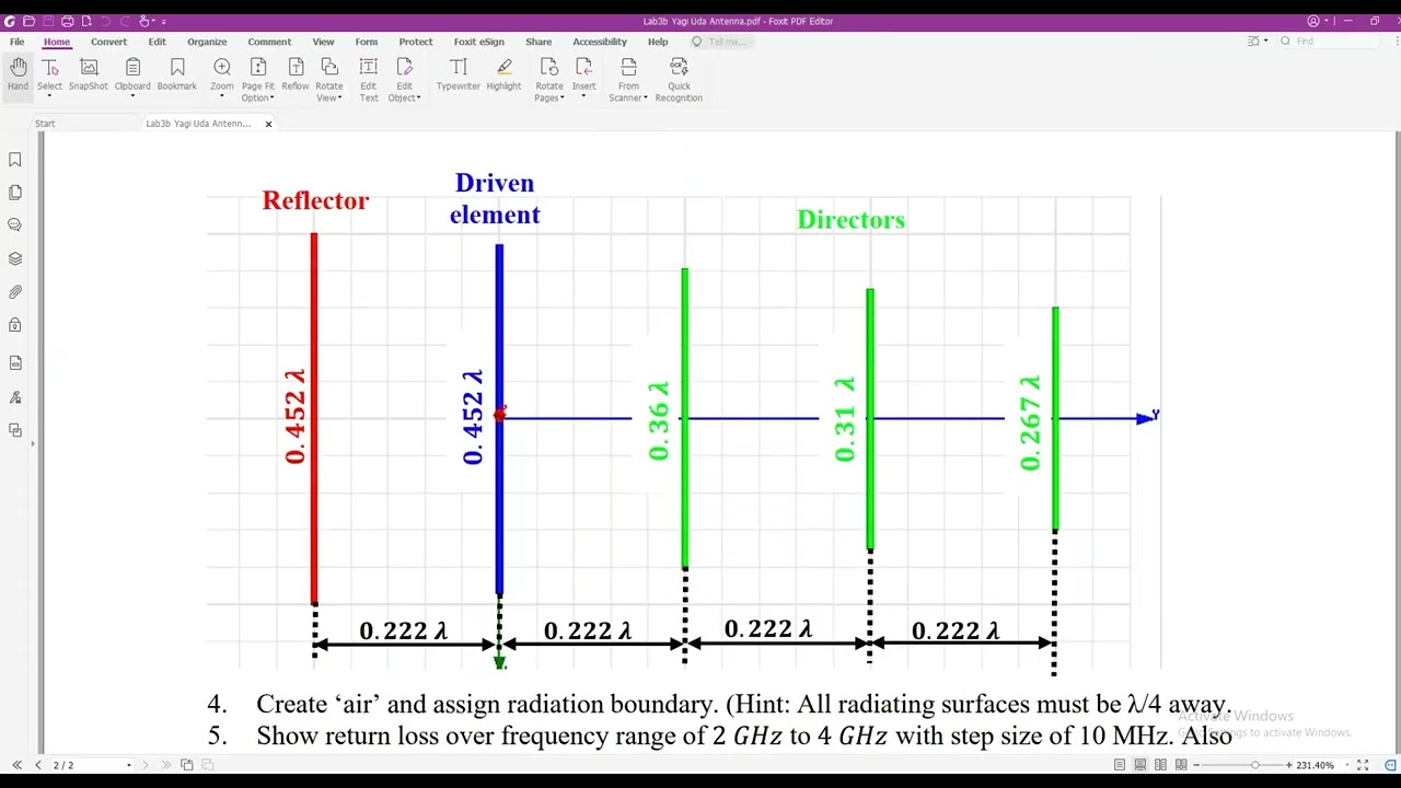










A Yagi-Uda antenna is a directional antenna array consisting of a single active half-wave dipole element, a larger reflector behind it, and multiple progressively smaller directors in front, mounted on a boom stick; the design follows specific geometric rules where the reflector is 5% longer than the lambda/2 dipole, each subsequent director is 5% shorter than the previous one, with spacing of 0.2λ between the dipole and reflector and 0.125λ between the dipole and first director, enabling more directional beam patterns as the number of directors increases.
Yagi-Uda Antenna Design: A Basic Tutorial for Engineers
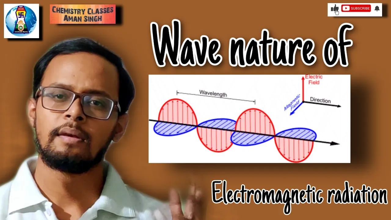
Added:Basic electromagnetic wave theory, including the relationship between frequency, speed of light, and wavelength.
Fundamentals of half-wave dipole antennas, as they form the core driven element of a Yagi-Uda array.
Key antenna performance metrics, such as radiation patterns, directivity, gain, and input impedance.
The concept of electromagnetic coupling and mutual impedance between closely spaced conductors.
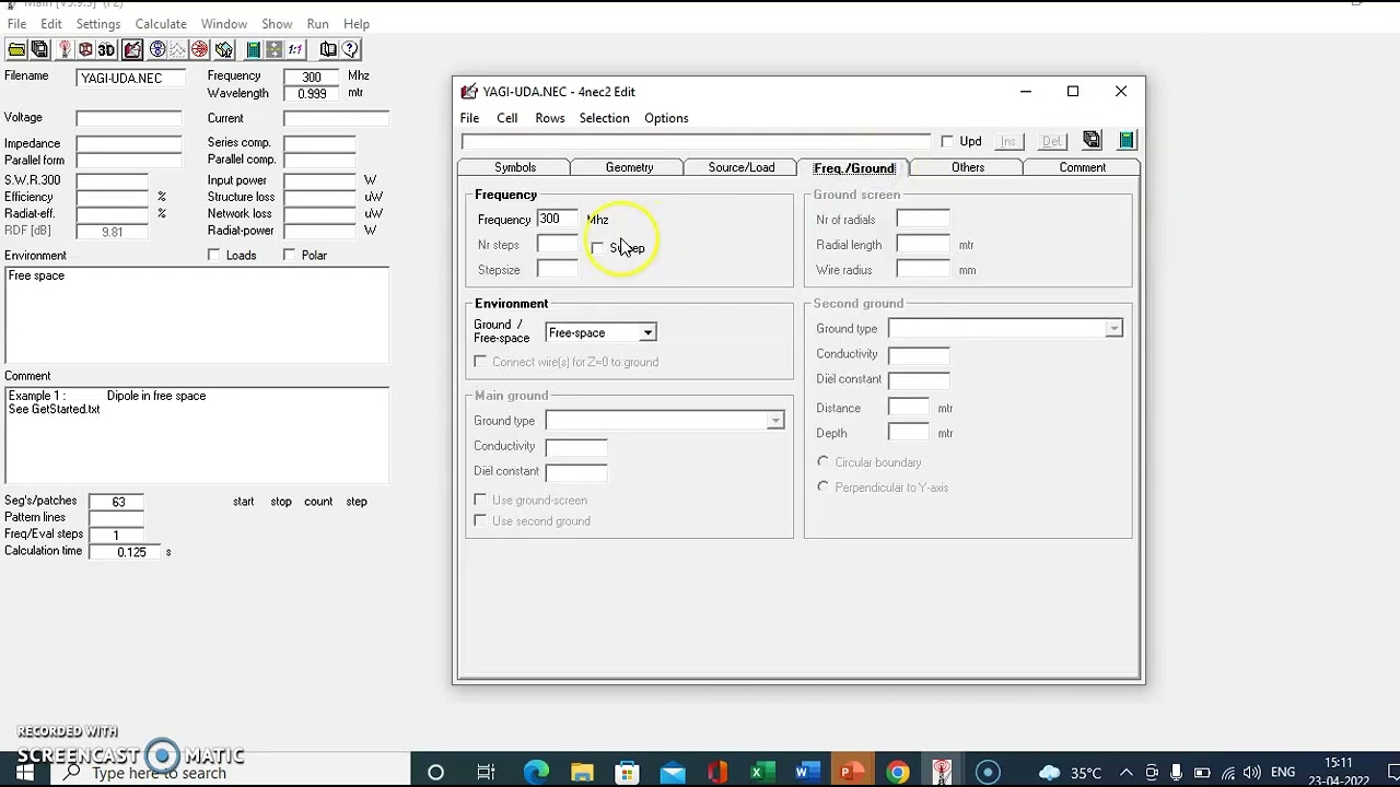
Use of antenna simulation software (such as EZNEC, HFSS, or CST) to model, analyze, and optimize Yagi-Uda designs.
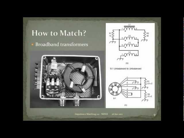
Design and implementation of impedance matching networks, such as Gamma matches, hairpins, and baluns, for practical feedline connection.
Advanced array configurations, including stacked Yagi arrays and log-periodic dipole arrays for wideband applications.
Mechanical engineering considerations for physical construction, such as wind loading, element sagging, and weatherproofing.
120.4K views1.4Klikes7:57Original Release: 2017-09-23
hello internet welcome to antenna tutorials in this tutorial I'll be designing a yahudah antenna this is one of the most basic type of antenna array and is designed from the most basic antenna that is the lambda by 2 antenna or the dipole now yahudah antenna is an example of an antenna array with a lot of parasitic elements now you must have seen this antenna from previous decades it used to be one of the most popular antennas around and this antenna had the shape of one active element and then it had a boom stick right in the middle this active element had a reflector at the back and it had numerous directors in the front now the basic concept of this antenna was to make a more directional antenna as opposed to the lambda by 2 dipoles which is an omnidirectional antenna the designing of this antenna used to be a manual word earlier because we needed to calculate the length of the lambda by 2 folded dipole and then each of these elements which are parasitic in nature that means that they are only going to manipulate the radiation of lambda by two active element antenna for example the work of reflector which is right behind the main element is to block the energy or radiation going in the backwards direction and these directors they they are used to direct the energy in a pencil beam manner then the more we have the number of Directors the more directional the beam would be the first now being width and the half Power Beam width will decrease as we increase the number of director elements it is pretty obvious that the reflector is a little bigger than lambda by two antenna and all the directors they are smaller than the main lambda by two antenna I assume that you know how to calculate lambda by 2 from the frequency given for example if you have 85 megahertz frequency you can calculate lambda as C by F and once you calculate lambda you can calculate lambda by 2 and that should be the length of your dipole or default dipole now each of these elements which are attached to the boom stick with reflector and directors their lengths are progressively increasing by 5% for example the reflector length will be lambda by 2 plus 5% added on top of lambda by 2 and similarly the first director will have a length lambda by 2 minus 5% of lambda by 2 and consequently if you go on to calculate second directors length it should be first director minus five percent less than the first director so that is how you can calculate the length of all the elements the inter spacing distance the distance between dipole and reflector should be point two lambda and the distance between dipole and director should be 0.125 lambda so on and so forth even in many books you'll find these values to be different by very small amount negligible amount but more or less these are the values that we need to follow to to design or construct he argues antenna and similarly the boomstick should have a maximum length which is specified by another formula and once you calculate all these lengths which are directly calculate table from the frequency you can easily design the yahoos antenna however today we do not use manual work for the calculation of the length we have argued the calculators which are Windows or Linux based applications that does all the work in the next tutorial I'm gonna focus on one of the other calculators that I use which is super easy to you use and it does a lot many functions that then any other manual person can do so thank you so much for watching this video make sure you watch the next part of this video where I demonstrate the software and have a good day good life bye
Up Next
10:10
Understanding VSWR and Return Loss | RF Power Transfer Basics
@Rohde-Schwarz
328.5K views•2019-10-18

30:32
Ultrasonic Transducers: Resonant Frequency Measurement and Horn Design
@imajeenyus42
229.9K views•2017-02-22

54:16
Polymer Environmental Degradation: Mechanisms & Stabilization
@iit
1.8K views•2012-07-10

33:39
How a Student's Question Saved a NYC Skyscraper from Collapse
@veritasium
22.8M views•2025-04-26
Related Study Plans & Knowledge Roadmaps
Structured learning paths in Engineering
engineering
Building Acoustic Levitators: Physics & Arduino
01The Physics of Sound and Standing Waves
02Piezoelectric Transducers and H-Bridge Drivers
03Arduino Programming: Generating 40 kHz Signals
+ 2 more learning modules
14h5 modules
Explore Roadmap
engineering
Building Peltier Cloud Chambers: Particle Tracks
01Cosmic Rays & Cloud Chamber Physics
02Thermoelectric Cooling (TEC) Fundamentals
03Custom Liquid-Cooling Loop Design
+ 2 more learning modules
18h5 modules
Explore Roadmap
engineering
Yagi-Uda Antennas: Modeling, Build & VNA Test
01Introduction to RF and Antenna Fundamentals
02Yagi-Uda Antenna Design Principles
03Antenna Modeling and Simulation in 4NEC2
+ 2 more learning modules
18h5 modules
Explore Roadmap
engineering
ECG Monitor Design: Op-Amps, Filters & Noise
01Electronics & Breadboard Basics
02Op-Amps and Instrumentation Amplifiers
03Bioelectricity and ECG Fundamentals
+ 2 more learning modules
18h5 modules
Explore Roadmap