





















![VNA: Selected Topics (part 3/3) [reupload]](https://i.ytimg.com/vi/CMHBavQSkiY/maxresdefault.jpg)

In RF systems, maximum power transfer occurs when source and load impedances are matched; impedance mismatches cause reflected power that reduces efficiency. VSWR (Voltage Standing Wave Ratio) measures this mismatch as the ratio of maximum to minimum voltage in a standing wave pattern, while Return Loss quantifies it in decibels as the difference between forward and reflected power. A VSWR of 1 indicates perfect matching with no reflection, while higher VSWR values indicate increasing reflection percentages—e.g., VSWR=3 means 25% of power is reflected. These parameters can be measured using network analyzers, and mismatches can be mitigated through matching networks or power reduction techniques called foldback.
Understanding VSWR and Return Loss | RF Power Transfer Basics
Added:Basic Transmission Line Theory: Understanding how electromagnetic waves propagate through a medium and the concept of characteristic impedance (Z0).
Wave Reflection Concepts: Understanding how voltage and current waves behave when encountering an impedance mismatch.
The Maximum Power Transfer Theorem: Grasping how source and load impedance matching maximizes power delivery in AC circuits.
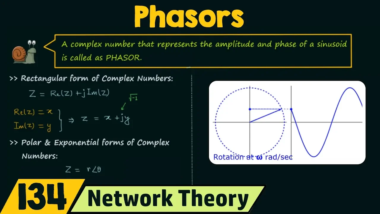
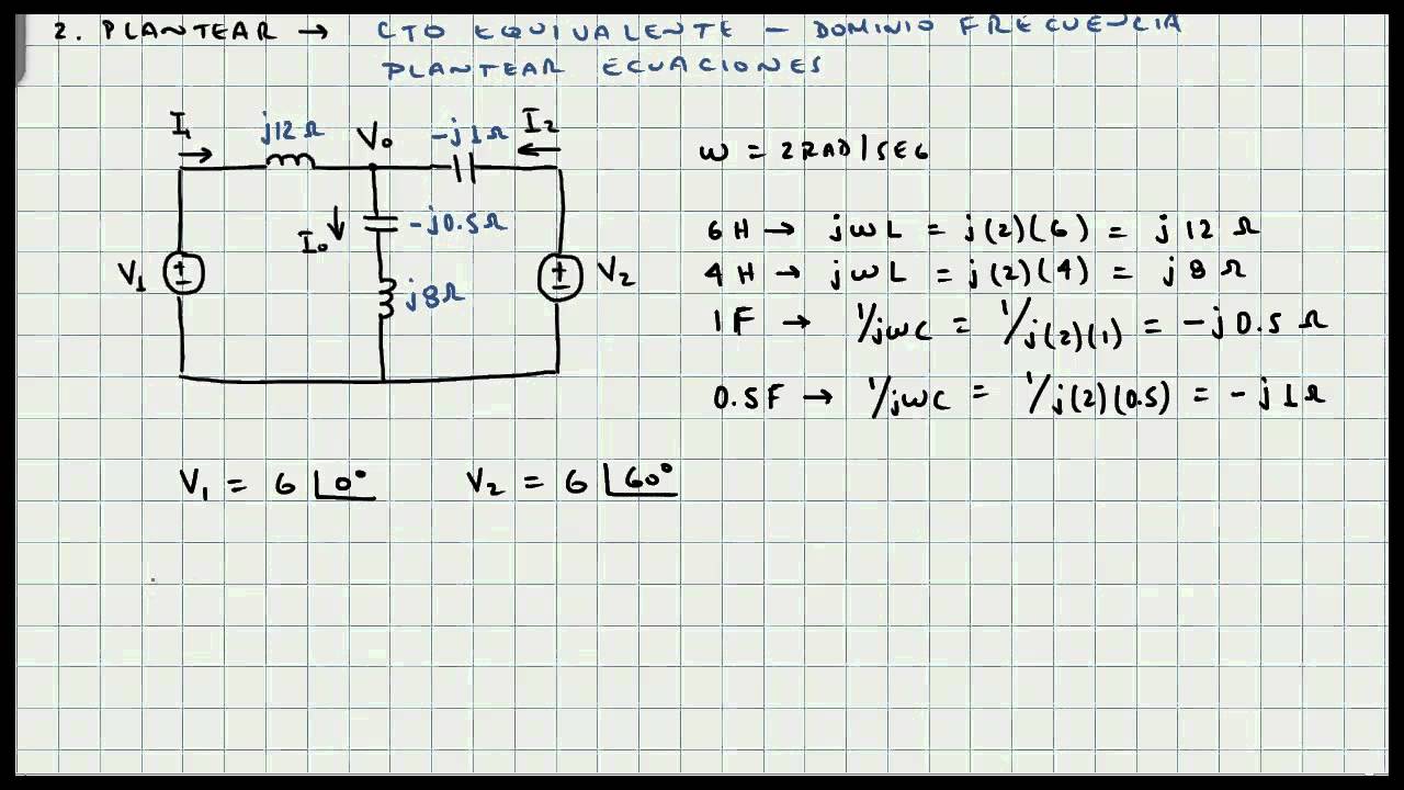
Complex Impedance and Phasors: Familiarity with resistance, reactance, and representing AC signals using complex numbers.
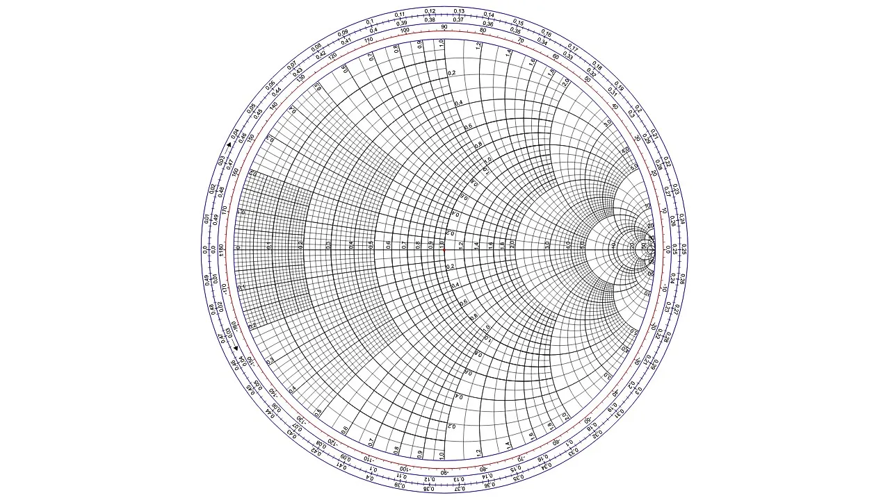
The Smith Chart: Learning how to use this graphical tool for visualizing impedance matching and reflection coefficients.
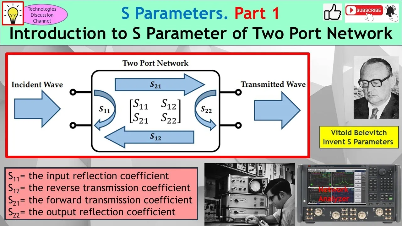
Scattering Parameters (S-parameters): Exploring S11 and its direct mathematical relationship to return loss and VSWR.
Impedance Matching Network Design: Designing L-networks, quarter-wave transformers, and stub tuners to minimize VSWR.
Practical RF Measurements: Understanding how to use a Vector Network Analyzer (VNA) to measure reflection parameters in real-world hardware.
328.5K views6.1Klikes10:10Original Release: 2019-10-18
Hello, and welcome to this presentation on Understanding VSWR and return loss. In this short presentation, we’ll discuss the technical concepts behind voltage standing wave ratio and return loss as well as how these quantities are measured.
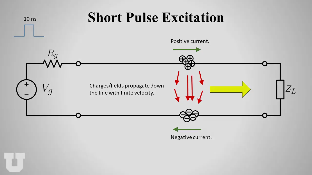
VSWR and return loss are both related to the transfer of radio frequency power, and efficient power transfer is one of the most fundamental concerns in radio frequency systems. Maximum RF power transfer occurs when the source of RF power and the load, or “sink” of that power have impedances that are “matched.” In this case, all of the RF power from the source is absorbed by the load. And in most cases, this is exactly what we want. The “standard” impedance in the RF world is usually 50 ohms, but you will also come across systems that use 75 ohms as a standard impedance, for example, cable television systems.
So what happens if there is a mismatch or difference between the source and load impedances? In this case, the impedance mismatch causes some of the power from the source, or the forward power, to be reflected from the load back towards the source – this power is called the “reflected” or “reverse” power. We’ll use the terms interchangeably in this presentation. Reflected power is almost always undesirable – there are very few cases where we would want ANY power reflected from the load back towards the source.
So far, we’ve shown our impedances as purely resistive values. But in reality, every load impedance is a complex impedance, consisting of both a real, resistive, part, and an imaginary, reactive part. A complex impedance is “matched” by its so-called complex conjugate, in which the sign of the imaginary part is reversed. At this point, it might be a good idea to pause for a brief refresher on impedance.
Remember that an impedance, Z, is a complex value that consists of two parts: a resistance, R, which does not change with frequency, and a reactance, X, which does change with frequency. Reactance can be further divided into capacitive and inductive reactance which are, not surprisingly, usually created by capacitors and inductors. Our complex impedance has both a magnitude and a direction.
It’s very important to remember that because of reactance, total impedance varies by frequency.
But how much does impedance vary by frequency? That depends on the load. A dummy load, for example, is usually a very resistive load that’s designed to have a constant impedance over a wide frequency range.
Most antennas, on the other hand, have an impedance that changes substantially by frequency. For this reason, most antennas have a specified frequency range over which they can, or should, be used. Note also that the impedance of an antenna in the real world is also dependent on the placement of the antenna relative to a ground plane or other nearby objects.
So if we were to use our mostly resistive dummy load as the load, the level of reflected power would remain low and roughly the same even as we change the frequency from 100 MHz to 200 MHz, 500 MHz, or even a GHz.
If, however, we use our antenna as the load, the level of reflected power will be a function of frequency. In this example, at 100 MHz the reflected power is only 4 watts. At 200 MHz the level of reflected power goes down to less than 1 watt. But at 500 MHz the level of reflected power is now 25 watts and increases to 50 watts at a GHz. Most real-world devices fall somewhere in between these two somewhat extreme cases of little impedance variation by frequency and large/irregular impedance variation by frequency.
So clearly, it’s important that we have some way of quantifying the level of reverse or reflected power, and in most cases, we want to do this relative to the level of forward power. There are actually two different ways that this relationship is quantified, these are return loss and voltage standing wave ratio, commonly called either VSWR or “VIZ-Wahr.” Let’s start by looking at return loss.
Return loss is nothing more than the difference in dB between the transmitted and reflected power. In other words, forward power minus reflected power equals return loss. For example, if our forward power is 50 dBm and our reflected power is 10 dBm, we have a return loss of 40 dB. Larger values for return loss mean that less power is reflected, so we usually want return loss to be as large as possible. And, of course, return loss must always be a positive number since the level of reflected power is always less than the level of forward power. Even in the case of a load that reflects 100% of the forward power, some power will be lost along the path from source to load and back.
The other quantity used to measure or quantify the level of reflected power relative to the level of forward power is something called VSWR, or voltage standing wave ratio. Here, the blue trace is the forward wave voltage, the red trace is the reflected wave voltage, and the purple trace is the combined voltage on the line. Note that the amplitudes of forward and reverse voltage remain constant, but the amplitude of the combined voltage trace, the purple trace, rises and falls over time, creating what is referred to as a “standing wave.” Voltage standing wave ratio is simply the ratio of the highest to lowest voltages in our standing wave.
In this example, the peak value is 3 and the minimum value is 1, so we have a VSWR of 3.
Many years ago, VSWR was calculated by physically measuring voltages at different points along the transmission line, but today VSWR can be automatically measured and calculated using a network analyzer. Mathematically, we calculate VSWR by determining the reflection coefficient, gamma, which is a function of the load impedance, Z sub L, and the source impedance, Z sub 0. Don’t forget that these impedances are complex, frequency-dependent values. Once we have gamma, VSWR is calculated by plugging gamma into another simple equation. We can also easily convert between VSWR and return loss.
Now that we know how to calculate VSWR, let’s look at what happens as VSWR increases. If the source and load impedances are matched, then VSWR is one and we have no reflected power – all power is absorbed by the load and none of it is reflected back towards the source. At a VSWR of 1.5, only 4% of total power is reflected. By the time we get to a VSWR of 3.0, a quarter of the forward power is reflected back to the source. This is still acceptable for many applications. But the percentage of reflected power increases dramatically as VSWR increases further. At a VSWR of 6, only about half of the forward power is absorbed by the load, and the remainder of the forward power is reflected back towards the source.
At VSWR equals 10, two thirds of the forward power is being reflected back.
There are two “special” cases we should discuss in terms of VSWR. The first of these is a short circuit. In this case, the load impedance equals zero and gamma equals minus 1. In the case of an open circuit, “load” impedance is infinite, and gamma equals 1. If you plug either one or minus one into the VSWR equation, you’ll get the same result – a VSWR of infinity, which means that 100% of the forward power is being transmitted back towards the source. Needless to say, having 100% of the transmitted or forward power reflected back towards the source is usually neither expected nor desired.
Setting aside these two extreme cases, what do we do about reflected power in general? One way to minimize the level of reflected power is to place a tuning or matching network between the source and the load. The matching network consists of impedances, usually in the form of capacitance and inductance, designed such that adding this additional impedance “matches” the load impedance to the source impedance. In this example we want to transform our complex load impedance to match the purely resistive 50 ohm source impedance. By selecting the appropriate values in the matching network we can change the overall load impedance to match the source impedance.
Another way to reduce the level of reflected power is to reduce the level of transmitted power. This is called “foldback” and is primarily used in higher power sources, such as broadband amplifiers. The main application of foldback is protecting the source from high levels of reflected power, which can cause performance degradation and even permanent damage in some cases. For example, let’s assume our source has a maximum safe reflected power level of 40 watts. If the level of mismatch is low, say, VSWR = 1.5, then with 100 watts of forward power, only four watts will be reflected back to our source. If VSWR were to increase to 6, the level of reflected power of 50 watts would exceed the safe limit. By lowering transmit power down to 80 watts, then the level of reflected power now falls again within the safe limit.
So let’s summarize what we’ve learned. First, maximum RF power transfer occurs when the impedance of the source and the load are matched. Impedances are complex, frequency-dependent values, and therefore a given impedance is matched by its complex conjugate, which we get by reversing the sign of the reactance, or imaginary part of the impedance. A mismatch between source and load causes some of the transmitted, or forward, power to be reflected by the load and returned to the source. The greater the degree of mismatch, the greater the level of reflections.
We can quantify the amount of reflected power as return loss or as the voltage standing wave ratio, or VSWR. The conversion between these two quantities is very straightforward.
Mismatched loads and reflections are not uncommon, and the two main ways of reducing reflected power are the use of matching networks and foldback. This concludes our presentation on “Understanding VSWR and Return Loss” – thanks for watching.
Up Next

41:01
Antenna Basics Class 1: RF Fundamentals & EM Waves
@hackaday
144.5K views•2021-07-15

30:32
Ultrasonic Transducers: Resonant Frequency Measurement and Horn Design
@imajeenyus42
229.9K views•2017-02-22

54:16
Polymer Environmental Degradation: Mechanisms & Stabilization
@iit
1.8K views•2012-07-10

33:39
How a Student's Question Saved a NYC Skyscraper from Collapse
@veritasium
22.8M views•2025-04-26
Related Study Plans & Knowledge Roadmaps
Structured learning paths in Engineering
engineering
Building Acoustic Levitators: Physics & Arduino
01The Physics of Sound and Standing Waves
02Piezoelectric Transducers and H-Bridge Drivers
03Arduino Programming: Generating 40 kHz Signals
+ 2 more learning modules
14h5 modules
Explore Roadmap
engineering
Building Peltier Cloud Chambers: Particle Tracks
01Cosmic Rays & Cloud Chamber Physics
02Thermoelectric Cooling (TEC) Fundamentals
03Custom Liquid-Cooling Loop Design
+ 2 more learning modules
18h5 modules
Explore Roadmap
engineering
Yagi-Uda Antennas: Modeling, Build & VNA Test
01Introduction to RF and Antenna Fundamentals
02Yagi-Uda Antenna Design Principles
03Antenna Modeling and Simulation in 4NEC2
+ 2 more learning modules
18h5 modules
Explore Roadmap
engineering
ECG Monitor Design: Op-Amps, Filters & Noise
01Electronics & Breadboard Basics
02Op-Amps and Instrumentation Amplifiers
03Bioelectricity and ECG Fundamentals
+ 2 more learning modules
18h5 modules
Explore Roadmap