






















An antenna is a transducer that converts guided electromagnetic waves (in waveguides or coaxial cables) into propagating waves in free space (for transmission) or vice versa (for reception), with key properties including radiation characteristics (reciprocity, gain, polarization, radiation patterns) and impedance properties (radiation resistance, loss resistance), where gain is measured in dB relative to an isotropic antenna (dBi) and efficient power transfer requires proper impedance matching to minimize reflections and maximize signal strength.
Antenna Basics Class 1: RF Fundamentals & EM Waves
Added:Basic Electromagnetism: Understanding electric (E) and magnetic (H) fields, and how they interact to form electromagnetic waves.
Wave Physics: Familiarity with wave properties such as frequency, wavelength, amplitude, phase, and the wave propagation equation (v = fλ).
Fundamental Circuit Theory: Understanding AC circuits, complex impedance (resistance and reactance), and basic voltage/current relationships.
Decibel (dB) Concepts: Knowing how to work with logarithmic scales, as dB and dBi are standard units for measuring power ratios and antenna gain.
Antenna Types and Design: Exploring specific antenna architectures like dipoles, monopoles, patch antennas, and Yagi-Uda arrays.
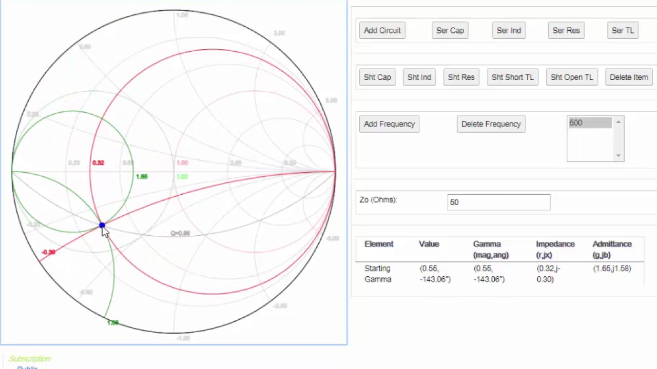
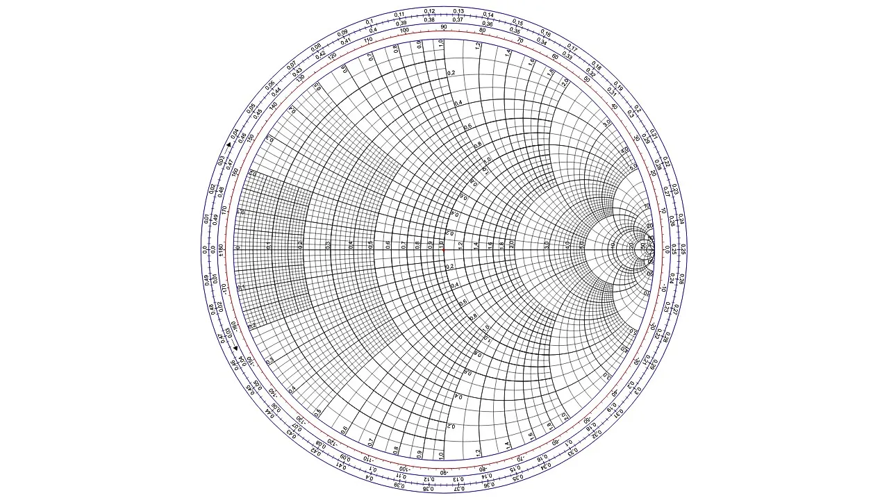
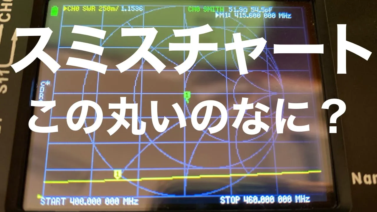
The Smith Chart and Impedance Matching: Mastering practical impedance matching techniques using Smith charts, microstrips, and lumped element networks (L-networks).
Radiation Patterns and Link Budgets: Calculating path loss, determining Effective Isotropic Radiated Power (EIRP), and designing complete RF link budgets.
RF Front-End Systems: Learning how antennas integrate with transceivers, low-noise amplifiers (LNAs), power amplifiers (PAs), and bandpass filters.
144.5K views3.9Klikes41:01Original Release: 2021-07-15
[Music] thanks everyone for putting up with us getting started my name is karen rucker and this is the introduction to antenna basics course with hackaday u thank you all for attending and this is going to be week one sort of an introduction to rf for antennas i know we have a wide variety of students in the class everyone from very seasoned amateur radio operators and people getting phds to people with no technical background whatsoever so i'm going to try to cater to that breath as much as possible i currently work as a satellite or spacecraft telecom engineer and my background is in antenna design i have an amateur radio license myself so i've done some hobbyist tinkering around but primarily this is going to be just an introduction to what you might encounter your first year as an antenna design engineer so let's get started okay so the week one class outline roughly is going to start very basic and some of the topics that we'll be referencing in the future so what's an antenna that's probably maybe important to start with an antenna class with i would be remiss if i didn't give a very brief overview over maxwell equations going into electromagnetic waves talking a little bit about polarization gain radiation patterns and then i'm very briefly going to touch on viswar or vswr for this class and impedance matching and frequency bands so first off what's an antenna besides something that can occasionally look like a funnel right so an antenna is just a transducer that converts energy from one domain into some other domain right and a transducer is just a fancy word for an electronic device that converts energy a microphone is a transducer right so what an antenna does is either converts a guided electromagnetic wave that's in a waveguide or in a coaxial cable into a propagating wave in free space if it's transmitting or vice versa if you're receiving right so it's just sort of a transfer function to get you from one domain to the other and generally we want a good electrical match at the antenna terminals and we want a good power transfer right we want it to be efficient so that we're not having loss and loss is a huge issue when you're working in rf or radio frequency and antennas right because often you're transmitting or trying to receive over long distances and you're losing power so we want to offset that by having an efficient system or as much so as possible as much as reasonable for what you're doing right and again i know that this can cover the gamma gamut from hobbyists that are kind of looking into playing with an antenna or this might give you some more information for working with antennas professionally so you're going to have different frames of reference for whatever you're doing and i'll try to give a shout out to that because i know again that there's a wide breadth of people in the class so some important antenna properties they can generally be classed into two divisions right we have our radiation properties and then we have our impedance properties radiation properties are going to be things like reciprocity the reciprocity theorem is essentially just that you can use an antenna for transmit and receive and that's important to know in this class today i'll be discussing the antenna pattern gain and polarization as far as impedance properties things like radiation resistance and loss resistance if you're doing a pure antenna design taking it as a class or doing it professionally you're going to know and learn how to derive those and evaluate those in your system i won't be covering those as much in class today i will touch on voltage standing wave ratio or viswar in this class as a side note some people have very strong opinions as to whether you say vswr or vizwar because engineers like to make arbitrary distinctions about things that don't matter sometimes it's just a cultural difference they mean the same thing right so i know some people like to tease a little bit but wherever you're with culturally however they do it is fine so first let's talk about isotropic antennas and so what does an isotropic antenna have in common with a pink llama unicorn under a rainbow they're the same thing they don't exist right so an isotropic antenna is this hypothetical antenna that has perfect same radiation in all directions in a perfect sphere right and this is something that some students struggle with understanding because you might think that you want your antenna to be as close to isotropic as possible or that this should be something that you strive for in your design and that's not actually true right the isotropic antenna is just a mathematical construct that we use as a frame of reference because frames of reference are important in physics um it you know has a gain of one db or one decibel in this spherical space and it has a perfect efficiency of 100 and i'll talk a little bit more about gain decibels and efficiency here later but the reason that i'm bringing this up right now is because when we talk about our intended performance antennas in real life we generally specify gain in dbi or decibels relative to an isotropic antenna so all that is is a ratio that we're giving in reference to this idealized mathematical construct so that's all you really need to know about it is just that it's a frame of reference that we use for our um antenna design going briefly into maxwell equations if you have a background in electrical engineering this is something that you were taught professionally and if you don't have that background that's perfectly fine um the most important uh one that will lead into our next slide is the last one right but what you need to know is that there are four maxwell equations we have gauss's law which is just a relationship between a static electric field and the electric charges that cause it we have that same gauss's law but for magnetism meaning that there's no individual magnetic charges um or magnetic monopoles it's always in a dipole form we have faraday's law which is that a time varying magnetic field creates or induces an electric field and that's very important for what we're about to talk about and then we have ampere's law that has maxwell's addition and that's magnetic fields can be generated in two ways by electric current and by changing electric fields so those last two are going to lead into how we get an electromagnetic wave and that's why i really wanted to cover them if you're going to learn antennas uh intended design through a course or take advanced coursework in it you're definitely going to want to know these and you're also going to want to know how to derive these into the electromagnetic wave equation right but that's very mathematical and that's not something i'm going to be covering here today i really just wanted to reference that the electromagnetic wave comes from these last two laws faraday's law and ampere's law with maxwell's addition and on the right if that looks like hieroglyphics to you that's perfectly fine if you're going to be doing antennas professionally or going into higher level coursework you're going to want to understand the vector calculus and vector operators that go into these equations very much but if you're just learning for fun then you're absolutely okay not paying attention to that so going into what an electromagnetic wave is as we talked about from those previous two uh maxwell equations the electromagnetic waves are composed of these oscillating magnetic and electric fields that are induced from each other right so you have your magnetic field which is generally kind of denoted as a b vector and you have your electric field denoted as your e vector and these propagate in an orthogonal direction orthogonal is just a fancy word for 90 degrees it's really fun to drop into everyday conversation but you have your magnetic field your electric field and your direction of propagation and here's what that looks like in gif form right we have these time varying oscillating waves and that is our construct of how this moves through space and the reason i'm starting at such a base level with what an electromagnetic wave is that this is important to understand what polarization is right which is important for your antenna design so note that the magnetic wave vector is moving in the z and x plane and the electric field vector is moving in that y x plane right again orthogonal to each other and orthogonal to the direction of propagation and so the electromagnetic spectrum spans a really wide range right and some of the important things to know about this are that wavelength and frequency are inversely proportional right the larger your wavelength the smaller your frequency is going to um be and you have different general uses for different frequency bands i'll talk about that a little bit more at the end of the class but generally what we're going to concentrate here are radio waves and primarily in microwaves which is the higher end of rf that i work in right but one of the cool things about the electromagnetic spectrum is that it's all the same spectrum right um i have a friend tess who tweeted something super funny today that light is just spicy radio waves right um and it was very clever and it's all the same spectrum but they all behave differently kind of depending on whether or not they're going through the atmosphere whether or not they're bouncing or reflecting off surfaces um but it's a good idea to have in mind not only what frequency you have to know what frequency you're designing for but also kind of what the different unique uh parameters are of that frequency right because of your wavelength size and you should generally know about the size of your wavelength right whenever you're designing with your frequency right you should have a good understanding of those in the relationship with each other so here's that same gif again and again the reason i said i wanted to bring this up is polarization and polarization is really just how the electric field vector moves and if this were going into a sheet of paper what it traces out what shape it traces out right so again we talked about the electric field and the magnetic fields vectors being orthogonal and a lot of times uh not in this depiction you'll see that k as being the direction of propagation that's where your wave is going right and the reason this is important to understand is because there are so many different kinds of polarization and because of that reciprocity theorem we want our transmitting antenna and our receiving antenna to have matched polarization or else you're going to have a mismatch a polarization mismatch which leads to loss so we have linear polarizations such as horizontal and vertical and you might see those in antennas like dipoles or yogis and something that was new to me that i just recently learned was slant polarization which is also linear that's often used in radar systems and then we have circular polarization such as right hand circular or left hand circular polarization which is a clockwise rotation and elliptical so i know that was a lot of words thrown out but let's look at linear polarization right horizontal and vertical so if we go back to that previous slide remember that we said polarization is just the pattern traced by that e field vector right so here the e field is moving up and down so what polarization is that it's linear and it's vertical right so that's all it is that's all that this is saying is that your e field is moving like this in this direction and one of the reasons that's important when i talked about mismatch loss you can kind of imagine if you have an electric field vector electric wave that is vertically polarized coming like this and because of reciprocity we want it to be the same but if it's meeting a horizontally polarized wave there's not a lot of match between my arm that's held vertically and my arm that's held horizontally right what we would want for a perfect match is for both of those to be the same we want it to be one to one if you are transmitting with a vertically polarized antenna into a horizontally polarized antenna you're going to have so much loss that you're probably not going to get the signal depending on how far away again how far away you are and how much gain you have but what you want the reason that you need to know this is because you want your antennas to have the same polarization so in here on the right is a depiction of circular polarization and circular polarization is it can be a little a bit harder or more steps to design for but it's frequently used in space applications particularly ground to space and space to ground because you don't have to worry as much about perfectly lining something up right think about it when you're however many hundreds or even millions of kilometers away it might be hard to get a one-to-one match if you were vertically polarized so the circular polarization can be a lot more forgiving in those situations and you can make several antennas that are linear into circular polarization depending on how you design them for example you can make this hornet antenna circularly polarized by simply having two ports feeding into it that are 90 degrees apart and you can do the same thing with like a yagi antenna that is like i said regularly linearly polarized okay so the important thing from these slides is that you want to intentionally design for your antennas polarization to match wherever you're trying to transmit or receive from so now i want to talk a little bit about gain briefly mentioned it before so antenna gain is just the power at the intended terminals and it includes antenna losses when you are studying antennas in an electrical engineering curriculum they're first going to introduce the concept of directivity to you right and occasionally as an antenna design engineer you might need to know directivity or you might need to plot it in a computer model or system but generally for practical applications we refer to gain because gain includes the efficiency of the antenna and it's not this idealized number right we want to include all the losses that are already in the antenna itself because that's the number that we're really going to use to get from one point to another and i mentioned previously that you need your gain to satisfy your link budget and a link budget is just a simple sum and subtraction total of all your losses and all your gains in the system if you have a number of your gain from your antenna and your transmitter then you have your loss that occurs over the free space and then if you have another gain and gaining your receiver and then maybe some loss from some cable you just want all that mathematically to add up that you can get to where you need to go right and one of the things about game that i frequently see in student rocketry projects is when they're building their ground system to connect to their uh rocket they want lots of gain because initially when you're first getting into antenna design you think i want all the gain possible that's the most important thing gain tends to be a trade-off with your radiation pattern and so you don't always need the most gain possible unless you're doing like a contest and you're trying to get the most gain uh and i know they have those for amateur radio conferences and such but you really have to consider the other things that your antenna has to says by besides just gain right and again this is typically given in dbi or decibels relative to an isotropic antenna um and so you'll see that pretty frequently there are other uh units that are sometimes used with antennas such as dvic decibels relative to isotropic circularly polarized antenna but generally speaking you're mostly going to see dbi so going into radiation patterns you want to design or pick an antenna design that satisfies the radiation pattern that you need right and so on the right we have a very directional radiation pattern and the main part of the beam that's going to come out is called the main lobe you might have a back lobe depending on what kind of antenna you're using and you might have side lobes so this is on the right a very directional antenna gain pattern right and so it's going to be a high gain it's very focused and you might see this from something similar to like a yogi antenna right but remember when i talked earlier about some mistakes that some students have made in their ground systems for having telemetry with their rockets they would choose a very high gain you know yagi antenna maybe something with 13 to 20 elements you know that's going to give you a lot of gain and it's going to have a very very focused beam the problem is that launching your rocket especially your own rocket is really exciting right um especially when you're there on the team and everyone's celebrating and so you have a student who's holding the antenna and they go to cheer with the team and they turn and with them turns the antenna if it's handheld and they've then lost the signal from the from their rockets telemetry and then they can't find it um and i i point this out because it's happened often enough times that i have to warn about it in one of the projects where i'm a judge and so it's a cautionary tale of absolutely having the highest gain is a not always suitable for the rest of your system requirements right it might be easier to have something that has a little bit of a broader radiation pattern like on the left and b it might not be worth the extra expense either if you're buying an antenna or the expense of your own time and energy and materials of trying to tune and intend to get a lot of gain so it is certainly important and it's a fundamental need to close a link but it's not always the end-all be-all when we're designing an antenna for our systems needs right so i'm going to briefly touch on this war in this course i'll talk about it a little bit more in the next course which goes over testing for antennas but this is going to lead into impedance matching which is important so typically there are two ways that we talk about having a good impedance match for an antenna right so we have uh this war also known as swr and we have meters that can measure that ratio of transmitted to reflected energy right and we want to have that be as close to one to one as possible and the lowest it can be is one and it can go up to infinity and if your viswara is infinity you have a really bad antenna right but it's always positive um and again that's the ratio of transmitted to reflected energy and if you think about it what do we want that ratio to be right we want everything to be transmitted and we don't want anything to be reflected back to us right we want for maximum power transfer for everything to go through through this port out instead of being reflected back into the rest of our system right i've seen uh this wire used more often in rf projects in the image community as a professional design engineer what i was more familiar with and what was uh culturally more common was the parameter of return loss which is sort of the same thing but not exactly right and we'll go into network theory a little bit more in the next class but what you need to know for here is that return loss is also known as s11 which is how much power is reflected at point 1 um that was transmitted in 2.1 right and because this is in db on the right and negative this varies from 0 to negative infinity so if you're used to one of these parameters or one of these types of measurement the other one might look a little odd to you because one is always positive and one should always be negative if you are getting a return loss or s11 of a positive number something is wrong something is broken right but it's really generally just kind of culturally what might happen in your team or your organization or what you're comfortable with right and there are as you can see on the screen from the bismarck equation there's ways to uh convert from one to another but again the whole point is that we want power any power that's incident or transmitted through this antenna we want it to go through we don't want it reflected back right because then it's going back into the rest of your system instead of going out where we want it to go so i talked about impedance matching so one of the prereqs for this course was some basic network theory and circuit theory and that's just because i didn't want to have to derive ohm's law or anything like that but impedance is exactly what it sounds like right it's the amount of opposition in a circuit right and if you are familiar with this you will know that impedance has both a real component which is the resistance and it has an imaginary component um if you're not familiar with that don't worry about the fact that it's imaginary but it's a reactants that can be either inductive or capacitive right so inductive that's for an inductor a passive component or capacitive from a capacitor and each of those has their own unique relationship with how they relate to current or voltage and the reason that you need to know this at least generally is because of impedance matching so what happens if i didn't start off with a perfect match from the impedance at this antenna terminal to whatever cable or waveguide that i want to hook it up to right well then i have to do some matching in between the two and all you're doing is introducing something a stop gap of the sorts that can help match those impedances between those two um systems right this can be done through a balance it can be done through introducing a capacitor or an inductor but the point of impedance matching is again we want to maximize that power transfer right and we want to minimize any signal reflection from the load or from this antenna right we want everything to go through so just know that you might have to do a little bit of tuning with whatever antenna that you ultimately design and people have to do this um even professionally right so it really should be expected it's not a sign that you were a terrible engineer if you have to do some impedance matching either because you designed it slightly off from what you needed to be or in some cases you might need to match something that is 50 ohms to a you know 300 ohm line and that's just the basic properties of the materials that you're working with right and how close you get this impedance match really depends on whatever requirements you're going for um as we talked about in this previous slide it talks about having the ratio be as close to one to one as possible and ideally you would have a perfect match right um but that's not always feasible even in industry right and this is going to depend on what kind of system you're working with for example if you are working with space components or anything that's going on a spacecraft you want it to be well matched right requirements or offerings for antennas for the space industry can be you know 1 to 1.1 or 1 to 1.2 that's how close the standing wave ratio match is right but if you're just goofing around it might be you know uh of this wire four you know something that you would normally not even think would even work right but you can have a perfectly matched dummy load something that doesn't radiate at all where the signal just goes in and is terminated or you can have a terribly matched antenna that is otherwise a perfectly good antenna so something to keep in mind is that you don't always have to aim for perfection if you're doing this for hobbyist reasons you really just want to get the most that you can reasonably that's going to satisfy the requirements of your system right and so on this class i'm going to focus more with the exception of the yogi's that will be kind of in the very high frequency range or vhf um this class will probably primarily focus on microwave frequency bands simply because that's what i have experience with and so you'll commonly see these uh referred to by their letter designations on the left and you should generally know if you're working in this domain what frequency range that matches up to and so for some examples l-band that's where gps frequency is uh s-band s as in c era and x as an x-ray bands are used uh frequently for telemetry tracking control operations in the space industry from space to ground and vice versa some of the upper bands such as k k a and v bands are often used for downlinking science data from space and you know various other applications x-band also has a marine navigational radar that's commonly used in that band one thing of note the letters aren't in alphabetical order i've been asked that before they have various like historical meanings you can look it up on wikipedia if you're interested in just knowing that kind of thing um but for example x-band was because of i think radar and um because it was introduced in i think world war ii it was x marxist spot that's where they came up with that declaration and from k u k and k a band k u is k under under k band and uh k a i think it has like a german uh background but it means like k after so you don't need to know that um but i know some people get confused because it's just alphabet gobbledygook and that part doesn't matter right um if you're working professionally in these bands you'll want to know what they are what they mean as far as your frequency range and kind of what to expect in your wavelength range and almost all antenna design that i've seen through university curriculum is always in metric units it'll give wavelength range in meters or centimeters and that's easy right when you're converting between wavelength and frequency because you're going to use the speed of light as you know 3 times 10 to the 8th meters per second right because all radio waves propagate at the speed of light however if you're in american industry they will actually frequently use um imperial units right uh in inches so that was a big surprise to me and something that you might be prepared for if you're going to work for american industry and if you are outside of american industry but still having to work with us you'll probably have to deal with our requests to have things in imperial units so just be prepared for that and my deepest apologies so and this is one of the last slides i wanted to go over we should have plenty of time for questions we have there's a wide range of applications and frequency bands for rf right and this can go from huge huge wavelengths that are used um particularly i think in hf or high frequency they will often use to study ionospheric effects particularly down at antarctica but what these acronyms mean is blf is very low frequency low frequency medium frequency high frequency because back in the day when they came up with that designation they thought um you know that was high frequency and now we're doing optical communications right with spacecraft which is extremely high frequency um but this kind of shows uh different bands and what they might be used for i know that amateur radio tends to be a little less popular in the microwave bands but that's primarily where your satellite and microwave telecom is going to be um that's where so this horn antenna that i keep holding up is an x-band horn from 10 to 12 gigs and we'll talk about that in one of the later classes i think on the microwave antenna application the yagi's that i'm most familiar with that i'll cover in one of the classes are vhf and also uhf right around there um but again here's those microwave frequency bands that i kind of just went over l s c x k u k and k a and those are generally how they're uh said k a instead of call and this graphic here has them as satellite frequency but that's just the notion in the graphic you can have those same bands on different stuff here on earth for example radars and other kinds of things like that one of the last things that i'll mention briefly is i've talked a lot about db which is the measurement for rf and again as i stated before dbi is decimals relative to an isotropic antenna that we use to measure gain and antennas with but it's just a change in power right and the key thing to remember is that the db value is a relative unit right it's a relationship of power out to power in so you always have something that it's in relation to when you're strictly talking in db but when you have things like dbm that's an absolute power that's going to be measured relative to one milliwatt because it has that very absolute power reference and the equation for db is 10 log because we are relating it to that power and i know some people get confused over when to use 10 log or 20 log and the difference is whether or not you are relating to power or to voltage and that comes from ohm's law right whether or not we have that squared but the key thing to remember is that it's 10 log 10 it's not natural log is how we measure db i have in my slides some additional resources of things that have helped me along the way of both kind of putting some of these slides together and trying to organize them in a reasonable fashion and things i also use my first year as an intended design engineer everything rf also has some good calculators of going in between wavelength and frequency or you know viswar to s11 and all those things ideally you should know how to do either by hand or from scratch but as a professional engineer you're just going to plug it into a calculator generally speaking even though that's not how they teach you in class but these are some of the ones that i've had a good experience with and as i briefly mentioned in the next class i'm going to talk about antenna testing so i'll go over a little bit more of the bizware network analyzers and s parameters i mentioned here there are more s parameters than just s11 right and i'll also talk about the far field and so my thinking was to give kind of a very basic background in this first class and then look at testing so that as soon as we go into design that you could have the background and have the testing knowledge to dive right in but that's planned for next class uh thank you so much for attending and i'm really excited to have our next class and i'll see you all in a week
Up Next

39:05
RF and Antenna Fundamentals for 802.11 Networks
@hankottey338
138.5K views•2015-09-17

30:32
Ultrasonic Transducers: Resonant Frequency Measurement and Horn Design
@imajeenyus42
229.9K views•2017-02-22

54:16
Polymer Environmental Degradation: Mechanisms & Stabilization
@iit
1.8K views•2012-07-10

33:39
How a Student's Question Saved a NYC Skyscraper from Collapse
@veritasium
22.8M views•2025-04-26
Related Study Plans & Knowledge Roadmaps
Structured learning paths in Engineering
engineering
Building Acoustic Levitators: Physics & Arduino
01The Physics of Sound and Standing Waves
02Piezoelectric Transducers and H-Bridge Drivers
03Arduino Programming: Generating 40 kHz Signals
+ 2 more learning modules
14h5 modules
Explore Roadmap
engineering
Building Peltier Cloud Chambers: Particle Tracks
01Cosmic Rays & Cloud Chamber Physics
02Thermoelectric Cooling (TEC) Fundamentals
03Custom Liquid-Cooling Loop Design
+ 2 more learning modules
18h5 modules
Explore Roadmap
engineering
Yagi-Uda Antennas: Modeling, Build & VNA Test
01Introduction to RF and Antenna Fundamentals
02Yagi-Uda Antenna Design Principles
03Antenna Modeling and Simulation in 4NEC2
+ 2 more learning modules
18h5 modules
Explore Roadmap
engineering
ECG Monitor Design: Op-Amps, Filters & Noise
01Electronics & Breadboard Basics
02Op-Amps and Instrumentation Amplifiers
03Bioelectricity and ECG Fundamentals
+ 2 more learning modules
18h5 modules
Explore Roadmap