Miller indices provide a standardized notation system for identifying crystallographic planes in crystal lattices by taking the reciprocals of the intercepts of a plane with the crystal axes and expressing them as the smallest set of whole numbers, enabling precise description and comparison of atomic arrangements in crystalline materials.
Miller Indices Explained with Animation | Crystallography Basics
Added:Deep Dive
Understanding of crystal lattices, Bravais lattices, and the definition of a unit cell.
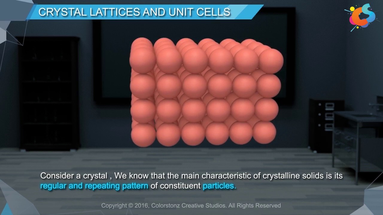
Crystal Lattices And Unit Cells
149.1K
A crystal lattice is a three-dimensional arrangement of constituent particles represented as points, with 14 possible types known as Bravais lattices; a unit cell is the smallest repeating portion of this lattice characterized by three edge lengths (a, b, c) and three angles (α, β, γ) that, when repeated in different directions, generates the entire crystal structure.
Click to watch →

What is a Unit Cell?
23.1K
Physicist Auguste Bravais proved there are exactly 14 possible ways to arrange points in 3D space to create repeating lattices that fill all space without gaps. These are called Bravais lattices. Any real crystal must conform to one of these 14 lattices. Unit cells are then defined by six parameters: three lengths (a, b, c) and three angles (α, β, γ). The lattice is a mathematical construct, while the crystal structure emerges when real atoms occupy lattice points. This framework simplifies understanding all possible crystal symmetries.
Click to watch →
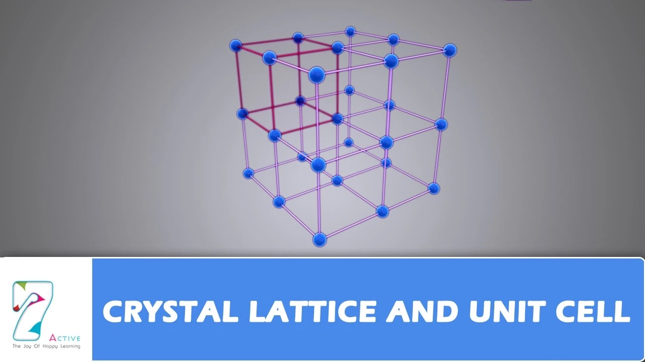
CRYSTAL LATTICE AND UNIT CELL
594.1K
A crystal lattice is a three-dimensional arrangement of particles as points in space, with 14 possible Bravais lattices identified by French mathematician Auguste Bravais; the unit cell, defined by parameters a, b, c (edges) and α, β, γ (angles), serves as the fundamental repeating unit of a crystal structure and is classified into primitive (particles only at corners) and centered types (body-centered, face-centered, and end-centered), while all 230 crystal forms are organized into 32 symmetry classes across seven crystal systems based on crystallographic parameters.
Click to watch →

Chemistry Class 12 Chapter 1 | Solid State | Thos Avastha | Class 12 Chemistry Chapter 1 | Chemistry
81.7K
A unit cell is the smallest repeating unit of a crystal lattice, defined by six parameters: three edge lengths (a, b, c) and three interaxial angles (α, β, γ). Based on these parameters, there are seven crystal systems: cubic (a=b=c, α=β=γ=90°), tetragonal (a=b≠c, α=β=γ=90°), orthorhombic (a≠b≠c, α=β=γ=90°), monoclinic (a≠b≠c, α=γ=90°≠β), triclinic (a≠b≠c, α≠β≠γ≠90°), hexagonal (a=b≠c, α=β=90°, γ=120°), and rhombohedral (a=b=c, α=β=γ≠90°). French scientist Auguste Bravais discovered that these seven crystal systems can be arranged into 14 distinct Bravais lattices, which are the fundamental building blocks of crystal structures.
Click to watch →

XII- 1 # 3, Lattices And Unit Cells
28.8K
A crystal lattice is a three-dimensional arrangement of points representing the regular pattern of constituent particles (atoms, ions, or molecules) in crystalline solids, while a unit cell is the smallest repeating structural unit that, when expanded in three dimensions, generates the complete crystal lattice; there are 14 types of Bravais lattices (named after Auguste Bravais) that describe all possible arrangements, and unit cells can be classified as primitive (particles only at corners), body-centered (one particle at center), face-centered (one particle at each face center), or end-centered (two particles at opposite face centers).
Click to watch →
Deep Dive
Familiarity with 3D coordinate systems, specifically crystallographic axes and fractional coordinates.

Crystallographic Points, Planes and Directions
22.1K
Crystalline materials use a right-handed coordinate system with axes a, b, and c at unit cell corners to specify points, directions, and planes. This applies even when axes aren't perpendicular (hexagonal, rhombohedral, monoclinic, triclinic systems). Crystallographic points are defined by q, r, s coordinates (relative distances along a, b, c from origin), written as three numbers without commas or brackets (e.g., 000 for origin, 100 for one unit along a, ½½0 for fractional positions).
Click to watch →

Miller Indices of Directions
220.2K
The crystallographic coordinate system uses the unit cell edges as its axes (x, y, z). Even in non-cubic crystals where angles between axes are not 90 degrees or where axes are not perpendicular, the coordinate system is always defined with axes parallel to the unit cell edges. This standardized approach ensures consistency across different crystal systems when specifying directions.
Click to watch →

Unit 2.6 - Fractional Coordinates
64.2K
Fractional coordinates are a coordinate system used in crystallography where atomic positions within a unit cell are specified as fractions (x, y, z) of the lattice constants a, b, and c, with values ranging from 0 to 1; this system allows immediate identification of special atomic positions such as corners (0,0,0), face centers (0.5,0.5,0), edge centers (0.5,0,0), and cell centers (0.5,0.5,0.5), making it more convenient than absolute coordinate systems for describing crystal structures.
Click to watch →

Índices de Miller e Planos Cristalinos (Ciência dos Materiais - aula 4)
4.8K
This comprehensive section covers the fundamentals of crystallographic coordinate systems and direction indices. The origin selection is not arbitrary because all lattice points are equivalent, though changing the origin alters absolute coordinates. The coordinate system (xyz) is established with the origin at a lattice point, and points are described by coordinates along each axis expressed in terms of the lattice parameter. The procedure for determining crystallographic directions involves: establishing the origin, determining coordinates of starting and ending points, subtracting base coordinates from endpoint coordinates, and multiplying by a factor to obtain integers. Examples include [011], [1̄01̄], and [111]. Negative values are represented with bars over numbers. Families of equivalent directions are denoted by angle brackets <uvw>, including <100>, <110>, and <111>. The direction of maximum atomic packing differs by structure: [111] for BCC and [110] for FCC, which are critical for understanding deformation mechanisms.
Click to watch →

Direções Cristalográficas (Índices de Miller) - Exercícios Resolvidos Callister (15)
18.6K
When direction vectors have fractional coordinates (like 2/3, 1/3), you must multiply all components by the least common multiple to convert them to integers. For example, a direction with components (2/3, 1, 0) requires multiplying by 3 to get (2, 3, 0), which becomes [230]. This process ensures Miller indices are always expressed as the smallest set of integers. The method involves: (1) identifying fractional components, (2) finding the least common multiple of denominators, (3) multiplying all components by this LCM, (4) simplifying if possible.
Click to watch →
Deep Dive
Basic mathematical competency in calculating reciprocals and finding the least common multiple (LCM).

pseb competency based paper class 9th maths worksheet 13 test 2024
11.3K
To find the LCM of reciprocals of factors of 8 (which are 1, 2, 4, 8), first find the reciprocals: 1/1, 1/2, 1/4, 1/8. The LCM of these fractions is found by taking the LCM of the denominators (8) and dividing by the GCD of the numerators (1). LCM = 8/1 = 8. Alternatively, convert to common denominator 8: 8/8, 4/8, 2/8, 1/8. The LCM is 8/1 = 8.
Click to watch →

चतुर्थ श्रेणी मॉडल पेपर 2025 || Kalam 4th Grade Maths model paper 2025 || चतुर्थ श्रेणी Maths
2.3K
To find the LCM and HCF of reciprocals: (1) For LCM of reciprocals, find the HCF of the original numbers and take its reciprocal, (2) For HCF of reciprocals, find the LCM of the original numbers and take its reciprocal. For example, reciprocals of 18 and 24: LCM of reciprocals = 1/HCF(18, 24) = 1/6, HCF of reciprocals = 1/LCM(18, 24) = 1/72.
Click to watch →

6 30
335
The least common multiple (LCM) of two numbers is the smallest positive integer that is divisible by both numbers, found by identifying common multiples and selecting the smallest one; for example, the LCM of 2 and 3 is 6. A reciprocal of a fraction is obtained by switching its numerator and denominator, and multiplying a number by its reciprocal always equals 1; for example, the reciprocal of 2/3 is 3/2, and 2/3 × 3/2 = 1. When dividing by a fraction, multiply by its reciprocal instead.
Click to watch →

WBP & KP Constable Math Practice Set-20 | WBP & KP Math Class | WBP SI Practice Set | WBP | KP #wbp
10.1K
When dividing fractions, multiply by the reciprocal. For example, 1/8 ÷ 1/4 = 1/8 × 4/1 = 4/8 = 1/2. The LCM of denominators helps simplify calculations.
Click to watch →

اتاكد واحل وافكر صفحه 136 و 137 و 138 رياضيات الصف الخامس الابتدائي
126.8K
The least common multiple (LCM) is the smallest positive integer that is divisible by two or more numbers. To find the LCM: (1) List multiples of each number, (2) Identify the smallest number that appears in all lists. Examples: LCM of 16 and 14 is 112; LCM of 9 and 12 is 36; LCM of 6, 10, and 15 is 30. LCM is used for scheduling recurring events and finding common denominators.
Click to watch →
Deep Dive
An introductory awareness of the seven crystal systems, particularly the cubic system.

Trick to learn seven crystal system|| class 12|| solid state
1.7K
The seven crystal systems can be memorized using the mnemonic 'KUT AWA MOTHER' (Cubic, Tetragonal, Orthorhombic, Monoclinic, Triclinic, Hexagonal, Rhombohedral), where each system has specific axial length relationships (a=b=c for cubic, a=b≠c for tetragonal and hexagonal, a≠b≠c for orthorhombic, monoclinic, and triclinic) and axial angle relationships (α=β=γ=90° for cubic, tetragonal, and orthorhombic; α=β=90° and γ=120° for hexagonal; α=γ=90° and β≠90° for monoclinic; all angles ≠90° for triclinic). The cubic system is the most symmetrical, while the triclinic system is the least symmetrical.
Click to watch →

टॉपर फैक्ट्री सीरीज़ | Chemistry | SOLID STATE (ठोस अवस्था) | Day-02
1.7K
There are seven crystal systems based on the unit cell parameters: (1) Cubic (a = b = c, α = β = γ = 90°), (2) Tetragonal (a = b ≠ c, α = β = γ = 90°), (3) Orthorhombic (a ≠ b ≠ c, α = β = γ = 90°), (4) Monoclinic (a ≠ b ≠ c, α = γ = 90°, β ≠ 90°), (5) Triclinic (a ≠ b ≠ c, α ≠ β ≠ γ ≠ 90°), (6) Hexagonal (a = b ≠ c, α = β = 90°, γ = 120°), and (7) Rhombohedral (a = b = c, α = β = γ ≠ 90°). The instructor emphasizes that cubic system is most important in the syllabus.
Click to watch →
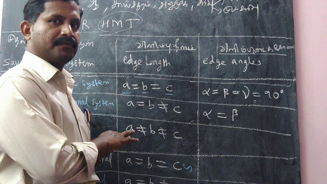
Solid State -seven primitive crystal systems
திட நிலைமை- எளிய அலகுக்கூட்டில் ஏழு
படிக அமைப்புகள்)
215
This segment introduces the seven crystal systems in solid state chemistry: Cubic, Tetragonal, Orthorhombic, Monoclinic, Triclinic, Hexagonal, and Rhombohedral. The instructor explains that crystal systems are classified based on edge lengths (a, b, c) and interaxial angles (α, β, γ). A mnemonic device 'கானா ஆ சாய் சதுரம் அறுமுக சரிவு' (Kanaa A Saa Sathuram Arumuga Sarivu) is provided, with English equivalent 'CD Oh HMT' to help students remember the seven systems. The Cubic system has a = b = c and α = β = γ = 90°, while the Tetragonal system has a = b ≠ c and α = β = γ = 90°.
Click to watch →

seven crystal system tricks||cubic crystal system||Chemistry By PC Sir
146
Crystals are always three-dimensional structures existing along three axes (X, Y, Z). Two essential parameters classify crystal systems: Edge Length (a, b, c) and Interfacial Angles (α, β, γ). Edge lengths have three situations: all equal (a=b=c), two equal with one different (a=b≠c), or all different (a≠b≠c). Interfacial angles also have three situations: all equal (α=β=γ), two equal with one different, or all different (α≠β≠γ). The seven crystal systems are Cubic, Hexagonal, Monoclinic, Orthorhombic, Rhombohedral, and Triclinic. A mnemonic '322 333 0' helps remember angle patterns: 3 indicates all three angles equal, 2 indicates two angles equal, and 0 indicates all three angles different. Cubic is the most symmetrical (a=b=c, α=β=γ=90°), while Triclinic is the least symmetrical (a≠b≠c, α≠β≠γ).
Click to watch →

Materials Science - Introduction to Crystals
496
The seven crystal systems are triclinic, monoclinic, orthorhombic, tetragonal, trigonal, cubic, and hexagonal. Each system is defined by specific relationships between the edge lengths (a, b, c) and angles (α, β, γ). The cubic system is particularly simple because all edges are equal (a = b = c) and all angles are 90 degrees, making it easy to work with and common in many materials.
Click to watch →
Prerequisite Knowledge
- Concept 01Understanding of crystal lattices, Bravais lattices, and the definition of a unit cell.
- Concept 02Familiarity with 3D coordinate systems, specifically crystallographic axes and fractional coordinates.
- Concept 03Basic mathematical competency in calculating reciprocals and finding the least common multiple (LCM).
- Concept 04An introductory awareness of the seven crystal systems, particularly the cubic system.
Subsequent Learning
- Step 01X-ray Diffraction (XRD) and Bragg's Law, linking Miller indices to experimental d-spacing calculations.
- Step 02The notation and determination of crystallographic directions [uvw] and families of directions <uvw>.
- Step 03Miller-Bravais indices (hkil) used to define planes and directions in hexagonal crystal systems.
- Step 04Analyzing mechanical properties of materials, such as slip planes and slip directions (slip systems) during plastic deformation.
Core concept
Deep dive
Core concept
1:30Playing Section
- 1
Introduces the central theme or question.
- 2
Sets the stage for further discussion.
Limitations in Non-Periodic Structures and the Challenge of Quasicrystals
While Miller indices are a fundamental tool for defining lattice planes in classical crystals with translational symmetry, they are insufficient for non-periodic structures like quasicrystals. Discovered in 1982, quasicrystals exhibit long-range order and rotational symmetry but lack translational periodicity. Consequently, standard three-dimensional integer Miller indices cannot describe their diffraction patterns. Instead, describing quasicrystals requires higher-dimensional crystallography, utilizing five or six indices, or alternative mathematical frameworks. Presenting this limitation broadens a student's perspective by showing that classical crystallographic notations are not universally applicable to all ordered solids.
Deep Dive
X-ray Diffraction (XRD) and Bragg's Law, linking Miller indices to experimental d-spacing calculations.

Bragg's Law and Miller indices | Yogi Joshi | Unacademy live
17.6K
Bragg's Law (nλ = 2d sinθ) describes X-ray diffraction from crystal planes, where n is the reflection order, λ is the wavelength, d is the interplanar spacing, and θ is the Bragg angle; Miller indices (hkl) are determined by taking reciprocals of the intercepts of crystal planes with the unit cell axes and converting to the simplest whole number ratio, and for cubic crystals, the interplanar spacing is calculated using d = a/√(h² + k² + l²), where a is the lattice parameter.
Click to watch →
Applied Physics - 2 | Most Important Questions | Detailed Solution | Unit-3 | GGSIPU
236
This section covers interplanar spacing calculations, Miller indices determination, and Bragg's law applications in X-ray diffraction. The interplanar spacing formula is: 1/d² = (h²/a²) + (k²/b²) + (l²/c²). For cubic systems, d = a / √(h² + k² + l²). For simple cubic: (100) plane: d = a; (110) plane: d = a/√2; (111) plane: d = a/√3. Miller indices are determined by taking reciprocals of intercepts and clearing fractions. For intercepts 3a, 4b, ∞: indices are (4, 3, 0). Bragg's law: nλ = 2d sinθ. For first order (n = 1) with λ = 1.449 Å and d = 4.255 Å: θ ≈ 9.806°. For second order (n = 2) with λ = 0.710 Å and d = 1.989 Å: θ ≈ 20.9°. The instructor emphasizes that smallest glancing angle means n = 1. These calculations are fundamental for crystallography and materials characterization.
Click to watch →

Lecture - 24 X-Ray Diffraction
194.7K
X-ray diffraction occurs when X-rays with wavelengths of approximately 1 Ångstrom interact with crystalline solids, where the periodic arrangement of atoms acts as a three-dimensional diffraction grating; each atom scatters X-rays through Thomson scattering, and constructive interference produces diffraction maxima according to Bragg's law (2d sinθ = mλ), where d is the interplanar spacing, θ is the grazing angle, m is the order of diffraction, and λ is the X-ray wavelength; the Miller indices (hkl) label different sets of parallel planes in the crystal, and the interplanar spacing is given by D = a/√(h² + k² + l²) for cubic crystals, enabling determination of crystal structure and lattice constants from the diffraction pattern measured by an X-ray diffractometer.
Click to watch →
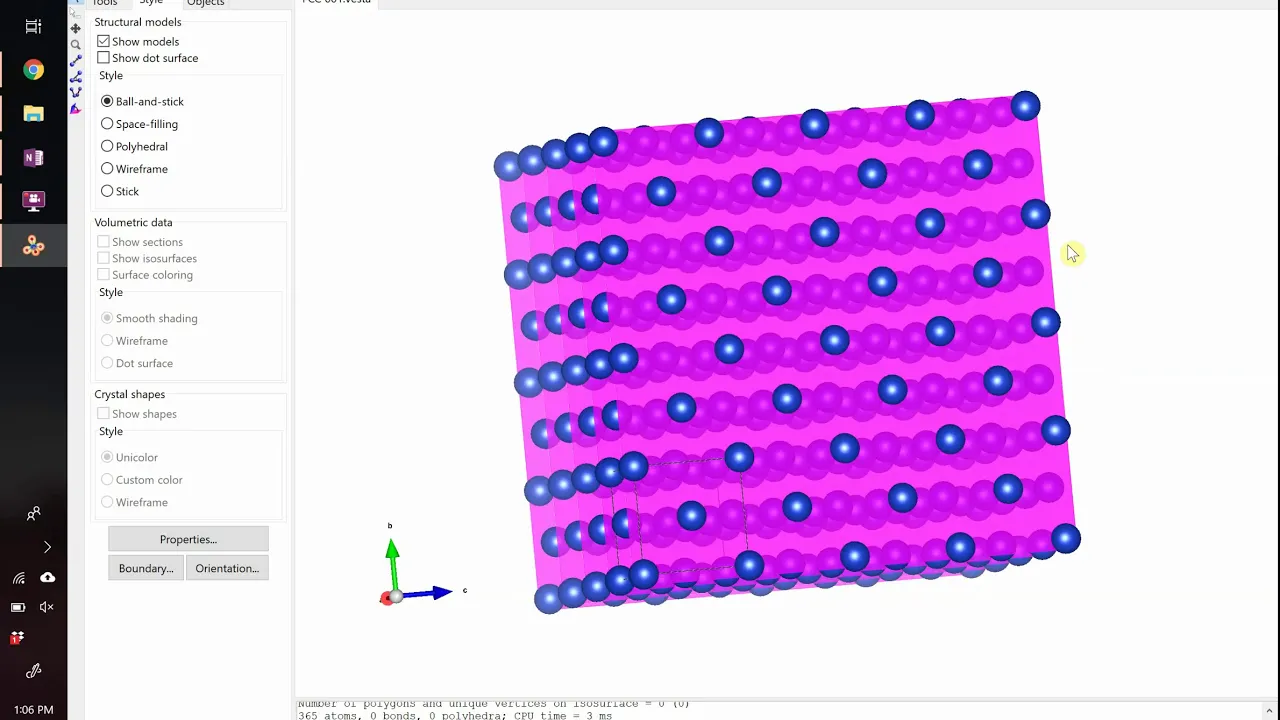
Introduction to X-ray Diffraction
15K
X-ray diffraction is a powerful technique for determining crystal structure by exploiting the wave nature of X-rays, which have wavelengths comparable to atomic separations (~1 nm). When X-rays strike a crystal, they interact with planes of atoms and produce constructive or destructive interference patterns depending on the angle of incidence and the interplanar spacing (d-spacing) of the crystal planes. William Bragg and his son Lawrence Bragg formulated Bragg's Law (nλ = 2d sinθ), which mathematically describes the condition for constructive interference and allows scientists to calculate d-spacings for different crystal planes. For cubic systems, the d-spacing can be calculated using the formula 1/d² = (h² + k² + l²)/a², where hkl are the Miller indices specifying the crystallographic plane and a is the lattice parameter. However, not all planes predicted by Bragg's Law produce observable diffraction peaks due to selection rules: for body-centered cubic (BCC) structures, diffraction occurs only when h+k+l is even; for face-centered cubic (FCC) structures, diffraction occurs only when all indices are even or all are odd. By measuring the angles at which diffraction peaks occur and comparing them to calculated values, researchers can identify unknown crystal structures using X-ray diffractometers and matching software.
Click to watch →

Bragg’s Law Explained | X-Ray Diffraction and Peak Indexing for Cubic Crystals
352.5K
Bragg's Law (nλ = 2d sinθ) describes the condition for constructive interference in X-ray diffraction, where X-rays reflecting from parallel atomic planes separated by distance d produce observable diffraction peaks when the extra path length equals an integer multiple of the wavelength; for cubic crystals, the relationship 1/d² ∝ (h² + k² + l²)/a² allows determination of lattice parameters and identification of crystal planes (such as (100), (110), and (111)) by measuring diffraction angles, calculating d-spacings, normalizing 1/d² values, and matching the resulting ratios to characteristic h² + k² + l² values.
Click to watch →
Deep Dive
The notation and determination of crystallographic directions [uvw] and families of directions <uvw>.
Miller Indices of Directions
220.2K
Miller indices are a standardized notation system for specifying crystallographic directions, determined through four steps: (1) choosing an origin on the direction, (2) defining a crystallographic coordinate system with axes parallel to unit cell edges, (3) finding coordinates of another point on the direction in terms of lattice parameters a, b, and c, then reducing to smallest integers, and (4) enclosing the three integers in square brackets [hkl]; negative components are denoted with a bar over the number, and equivalent directions related by crystal symmetry are grouped using angular brackets <uvw>.
Click to watch →
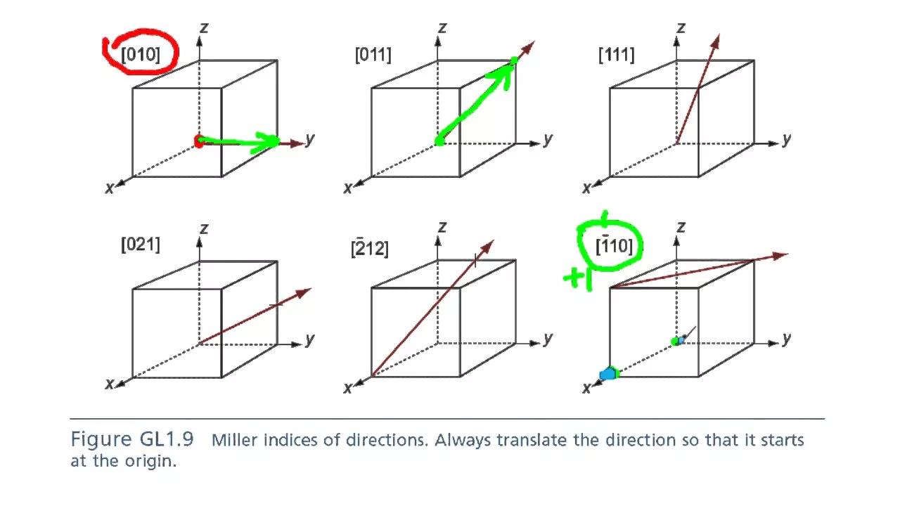
crystallographic directions
809.6K
Crystallographic directions in crystal structures are represented by Miller indices written in square brackets [hkl], where the direction vector is determined by placing its tail at the origin (or moving the origin +1 for negative indices) and finding the endpoint based on the indices; when indices contain fractions or numbers greater than 1, common factors should be removed to simplify the direction, and families of directions include all permutations and reciprocals of the base indices.
Click to watch →

Solid State | Miller Indices | CSIR NET | Gate | IIT -JAM | DU | BHU | Chem Academy
22.7K
Direction indices (uvw) represent directions that are perpendicular to crystal planes. The notation [uvw] indicates a direction vector that is normal to the plane (hkl). Direction indices are always perpendicular to their corresponding Miller indices. Direction indices represent a set of parallel directions, similar to how Miller indices represent a set of parallel planes. The notation [uvw] indicates all directions that are parallel to each other and have the same orientation relative to the crystal axes.
Click to watch →

Kübik Kristallerde Yönler ve Doğrultular (Miller indisleri)
49.7K
Miller indices [uvw] are used to describe crystallographic directions in cubic crystals, where indices represent the number of unit cell lengths traversed along each axis; equivalent directions are denoted by angle brackets <uvw> and can be generated by permuting indices or changing signs, while the angle between two directions is calculated using the dot product formula: cos(θ) = (u1u2 + v1v2 + w1w2) / (√(u1² + v1² + w1²) × √(u2² + v2² + w2²)).
Click to watch →

BARC Stipendiary Trainee Interview Approach for Material Science & Manufacturing | Live Session
4.5K
Crystallographic directions are represented by square brackets [uvw], indicating vectors from origin to points. Miller indices (hkl) in parentheses represent crystallographic planes. Directions are defined by lines between two points, while planes are defined by three points. Families of directions with same linear density are represented by angular brackets <uvw>. Linear density is atoms per unit length along a direction.
Click to watch →
Deep Dive
Miller-Bravais indices (hkil) used to define planes and directions in hexagonal crystal systems.

Solid State Physics I Lecture -4 I CSIR NET JRF I IIT JAM I GATE I By Himanshu Sir
1.5K
For hexagonal crystal systems, Miller-Bravais indices (hkil) are used. The relationship is: h = H, k = K, i = -(H+K), l = L. The fourth index 'i' is redundant because i = -(h+k). For example, (112) in Miller indices becomes (11-22) in Miller-Bravais indices. This conversion is essential for hexagonal crystal systems where standard Miller indices are insufficient.
Click to watch →

#7 Crystal Structure | Miller Bravais Indices | Linear & Planar Density | Part 5
62.2K
Miller-Bravais indices (hklm) are a four-index notation system specifically designed for hexagonal close-packed (HCP) crystal structures, which extends the conventional three-index Miller indices to account for the unique symmetry of hexagonal systems; this system uses intercepts on the four hexagonal axes (a₁, a₂, a₃, and c) to define crystallographic planes and directions, enabling accurate representation of the hexagonal symmetry where the three basal axes are equivalent but differ from the c-axis.
Click to watch →

Lecture 05: Crystal planes and directions: Indexing
41.6K
The Miller indexing system (proposed by William Miller in 1839) provides a standardized method for naming crystal planes and directions using integers enclosed in square brackets for directions [uvw] and parentheses for planes (hkl). For directions, the procedure involves: (1) repositioning the vector to pass through the origin, (2) finding the projection lengths along crystal axes, (3) converting fractions to lowest integers by multiplying by a common factor, and (4) enclosing the result in square brackets. For planes, the procedure involves: (1) finding intercepts with crystal axes, (2) taking reciprocals of these intercepts, (3) converting fractions to lowest integers, and (4) enclosing the result in parentheses. Negative values are denoted by placing a bar over the number. For hexagonal crystal systems, the Miller-Bravais four-index system (hkil) is used, where i = -(h+k), to ensure equivalent planes and directions have similar indices.
Click to watch →

Miller-Bravais Indices: Hexagonal Structure
274.8K
In hexagonal crystal systems, Miller-Bravais indices use four parameters (h, k, i, l) instead of three, where the first three indices follow the relationship h + k + i = 0 due to the 120-degree symmetry between the three a-axes; to determine these indices, find where a plane intersects the four axes (a₁, a₂, a₃, and c), express these intersections as multiples of the unit cell dimensions, take the reciprocal values, and simplify to integers, with negative values indicated by a bar over the number.
Click to watch →
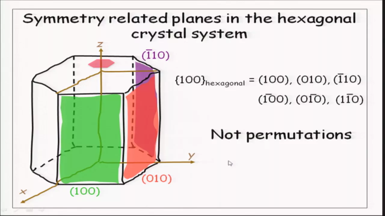
Miller-Bravais Indices for hexagonal crystals
95.3K
The Miller-Bravais indexing system (hklm) is a four-index notation specifically designed for hexagonal crystals to address the limitation that symmetry-related directions and planes cannot be represented as simple permutations in the standard three-index Miller system; this system introduces a redundant third axis in the basal plane such that the sum of the first three indices equals zero (h + k + l = 0), ensuring that symmetry-equivalent directions and planes become permutations of each other, with the conversion formulas from three-index (uvw) to four-index (UVTW) being U = (2u - v - w)/3, V = (2v - u - w)/3, T = (2t - u - v)/3, and W = w.
Click to watch →
Deep Dive
Analyzing mechanical properties of materials, such as slip planes and slip directions (slip systems) during plastic deformation.
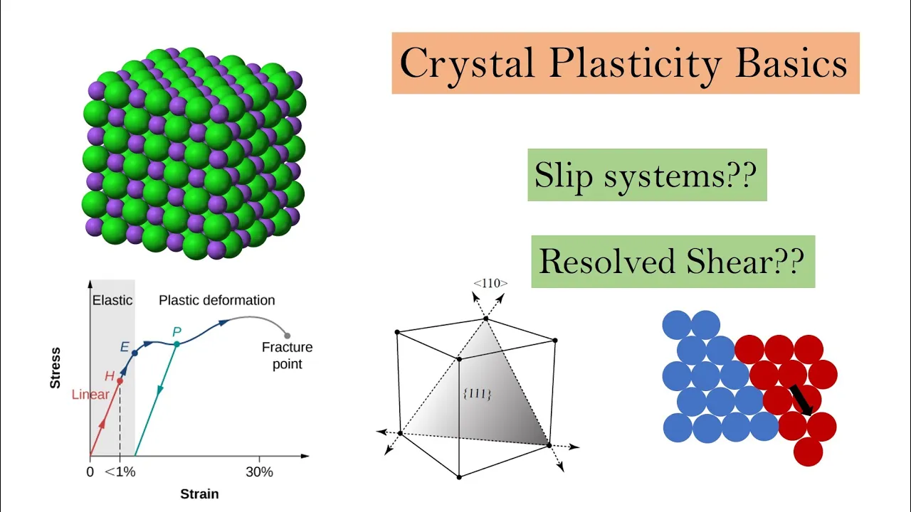
Crystal Plasticity Basics Part 1
22.1K
Slip systems combine slip planes and slip directions to enable atomic sliding. Slip systems depend on crystal structure (FCC, BCC, HCP), material composition (single-element vs compounds), atomic size differences, and bond type. Face-centered cubic metals have 12 slip systems: 4 slip planes with 3 slip directions each. The total slip systems equal the product of slip planes and slip directions per plane. These factors determine how easily and in what ways a material can deform plastically.
Click to watch →

Slip
85.4K
Slip is the primary mechanism of plastic deformation in crystalline materials, where unit cells slide over one another along specific crystallographic planes (slip planes) and directions (slip directions), forming slip systems; different crystal structures exhibit distinct slip system characteristics—cubic close-packed (CCP) materials possess 12 slip systems on {111} planes along <110> directions, hexagonal close-packed (HCP) materials have only 3 slip systems on (001) planes along <112̄0> directions, and body-centered cubic (BCC) materials have 12 slip systems on {110} planes along <111> directions—which directly influences their ductility versus brittleness.
Click to watch →
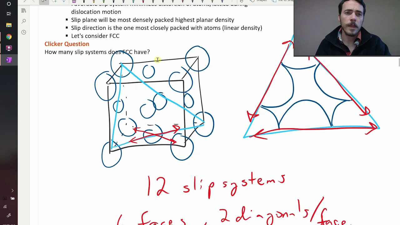
Slip systems
68.2K
Slip systems are the lowest energy pathways for plastic deformation in crystalline materials, consisting of the highest planar density plane combined with the highest linear density direction within that plane. In FCC crystals, this results in 12 slip systems (6 faces × 2 directions each), while HCP crystals have only 3-6 slip systems confined to the basal plane. The number of slip systems directly determines a material's ductility—FCC materials are highly ductile due to abundant slip systems, whereas HCP materials are more brittle because fewer atomic sliding pathways exist for accommodating strain.
Click to watch →

Slip planes and slip directions
89K
This comprehensive section covers the fundamental principles of plastic deformation in metals through dislocation motion. Metals possess greater dislocation density than ceramics due to non-directional metallic bonding enabling easy atomic hopping. Plastic deformation occurs via slip where edge dislocations slide over adjacent atomic planes along slip systems. Slip planes are selected based on highest planar density and interplanar spacing, while slip directions are chosen for highest linear density to minimize atomic hopping distance. FCC metals have 12 slip systems on (111) planes along <110> directions, while simple cubic crystals use (100) planes with <010> slip directions. Moving dislocations create compression and tension zones that interact through strain energy considerations, with like charges repelling and unlike charges attracting, causing opposite dislocations to annihilate and restore perfect crystal structure.
Click to watch →

MSE 201 S21 Lecture 22 Module 4 - Slip Systems
15.3K
A slip system consists of a slip plane and slip direction where dislocation motion occurs during plastic deformation. Slip planes are crystallographic planes with highest planar density where atomic planes slide past each other. Slip directions are lattice directions with highest linear density, aligned with the Burgers vector. In FCC crystals, slip occurs on (111) close-packed planes in <110> close-packed directions, yielding 12 equivalent slip systems due to crystallographic equivalence. This systematic approach of combining high-density planes with high-density directions determines the ease of plastic deformation in crystalline materials.
Click to watch →
Core concept
Deep dive
Core concept
1:30- 1
Introduces the central theme or question.
- 2
Sets the stage for further discussion.
Limitations in Non-Periodic Structures and the Challenge of Quasicrystals
While Miller indices are a fundamental tool for defining lattice planes in classical crystals with translational symmetry, they are insufficient for non-periodic structures like quasicrystals. Discovered in 1982, quasicrystals exhibit long-range order and rotational symmetry but lack translational periodicity. Consequently, standard three-dimensional integer Miller indices cannot describe their diffraction patterns. Instead, describing quasicrystals requires higher-dimensional crystallography, utilizing five or six indices, or alternative mathematical frameworks. Presenting this limitation broadens a student's perspective by showing that classical crystallographic notations are not universally applicable to all ordered solids.
Understanding of crystal lattices, Bravais lattices, and the definition of a unit cell.
Familiarity with 3D coordinate systems, specifically crystallographic axes and fractional coordinates.
Basic mathematical competency in calculating reciprocals and finding the least common multiple (LCM).
An introductory awareness of the seven crystal systems, particularly the cubic system.
X-ray Diffraction (XRD) and Bragg's Law, linking Miller indices to experimental d-spacing calculations.
The notation and determination of crystallographic directions [uvw] and families of directions <uvw>.
Miller-Bravais indices (hkil) used to define planes and directions in hexagonal crystal systems.
Analyzing mechanical properties of materials, such as slip planes and slip directions (slip systems) during plastic deformation.
600.9K views12.8Klikes5:13@telutron9755Original Release: 2022-01-15
[Music] so [Music] do [Music] you
Up Next
3:36
Crystalline Solids, Unit Cells & Space Lattices Explained
@AcademicGainTutorials
8.2K views•2020-04-05

12:53
21cm Hyperfine Transition in Neutral Hydrogen: Radio Astronomy Basics
@AaronRobertParsons
12.4K views•2011-10-13

32:32
NMR Spin Physics I: Zeeman Effect, Resonance Condition & Larmor Frequency
@nptel-indianinstituteofsci8064
2.3K views•2024-01-17

27:14
Entropy and the Second Law of Thermodynamics Explained
@veritasium
27.5M views•2023-07-01
Related Study Plans & Knowledge Roadmaps
Structured learning paths in Physics
physics
Nuclear Physics (Decay, Fission & Reactors)
01Atomic Structure and the Binding Force
02Radioactive Decay and Half-Life
03Nuclear Fission Mechanics and Chain Reactions
+ 2 more learning modules
12h5 modules
Explore Roadmap
physics
Soft Matter (Polymers, Colloids & Rheology)
01Foundations of Soft Matter & Thermal Forces
02Polymer Physics and Macromolecules
03Colloids, Surfactants, and Self-Assembly
+ 2 more learning modules
38h5 modules
Explore Roadmap
physics
Analytical Mechanics: Lagrangian & Hamiltonian
01Mathematical Foundations: Calculus of Variations
02From Newtonian Mechanics to Constraint Dynamics
03The Principle of Least Action & Lagrangian Mechanics
+ 3 more learning modules
28h6 modules
Explore Roadmap
physics
General Relativity (Spacetime & Cosmology)
01Foundations of Relativity: Special Relativity
02The Geometry of Spacetime: Equivalence Principle & Curvature
03Einstein's Field Equations: The Mathematics of Gravity
+ 2 more learning modules
55h5 modules
Explore Roadmap