





![CNC Router electrical wiring 230v AC for VFD and 48v DC power supplies, HOW TO.[Episode 14]](https://i.ytimg.com/vi/hEF4qddlpgU/hqdefault.jpg)














This video demonstrates the integration of ODrive brushless motor drivers with a Teensy 4.1 microcontroller for controlling a robot dog's six motors, using magnetic encoders for position feedback and a separate power distribution system to ensure stable 5V power for sensitive electronics while powering the motors from a 6-cell LiPo battery.
Building a Quadruped Robot: Electronics Assembly and Power-Up
Added:Understanding of Brushless DC (BLDC) motor principles and the difference between brushed and brushless motor commutation.
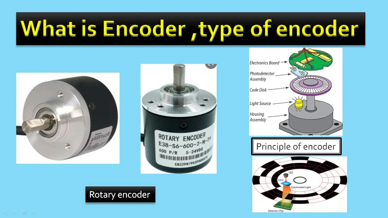
Basic knowledge of rotary encoders (absolute vs. incremental) and their role in closed-loop feedback systems.
Fundamentals of DC power distribution, including voltage, current capacity, and safe wiring practices for high-draw robotics components.
Concept of motor drivers and controllers, specifically Field-Oriented Control (FOC) or ESCs (Electronic Speed Controllers).
Tuning Field-Oriented Control (FOC) parameters (proportional, integral, derivative gains) for optimal joint response.
Implementing Forward and Inverse Kinematics to translate desired spatial foot trajectories into joint angle commands.
Developing quadruped gait generators (e.g., trot, walk, bound) using software state machines or trajectory planning.
Advanced force and impedance control to enable active compliance and terrain adaptation when interacting with the ground.
92.8K views4.6Klikes16:13Original Release: 2020-06-23
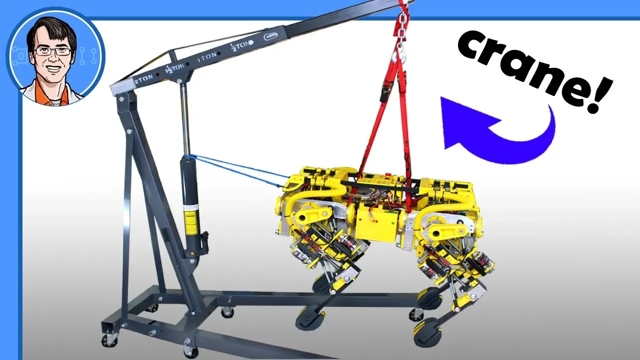
hello it's part 4 of open dog version 2 first of all I put the whole thing on a stand and it's rather satisfying speed to pick the whole thing up which I can do quite easily the weight of this just without the electronics of the moment is about 14 and a half kilograms and we put the mechanical assembly together in the last video so they forget to check that out as well as the one before where we built a single test leg to work out how much load we could put on the top and that's how we drew the conclusion that this is probably going to work okay and it's definitely fast enough as well today we're gonna put the electronics in and hopefully power it up and this stand is just made of twenty twenty extrusion and since 3d prints on I've got these little stirrups here so the feet can rest on there cuz otherwise they want to fall into the middle because of the mass distribution so that'll help me when I power out the legs to do the initial calibration and it looks nice sound it stand without the legs flopping in and touching each other in the middle it's like we're going to be using the O Drive to control all these brushes motors I'm gonna be using six of them in fact but we need to mount those somewhere in the chassis there's plenty of space in the middle right now so we're gonna try and put them in there but we need to make a mounting rig for three at each end of the dog and that looks like a thing that clips onto the rails that we've got here and sits right down in the middle of the dog and there's plenty of clearance there for plenty of things that can be just lifted straight out and it's going to be zipped tied in using some zip ties around these channels and we've got the three O drives in there and I'm just basically squeezing the corner of those boards in a 3d printed rig that's gonna drop in and that should give us easy access and easy access to all of the connectors so here are my parts to mount those drives and what we've got here is six o drives these are the ones out of the original open dog project so these are actually Oh dry 3.5 s they're not the three point six which is the latest version but they're raising up to 48 volts and we'll put the latest firmware on so that should be more than good enough so here are my three o drives and those are just mounted by putting them into slots which should hold them pretty well so we'll just put the top back on and then of course we screw the sides on which you've got the ears and hold the top and bottom and that should drop into the dog so that should drop straight in there which seems to work pretty well and there's plenty of clearance on the middle we've also got a voltmeter here which is just a panel meter and that'll carry two bits of studying for power distribution the O drives are actually capable of reporting the bus voltage so eventually we'll build a fancy control of the reports it digitally but for starters I want to keep an eye on the battery voltage at the back of course we've got another three O drives because we need six in total each o drive controls two motors and there's 12 motors which is three in each of the four legs we've also got an emergency stop button and that's just going to reset all the O drives it takes the reset pin to ground now immediately cut the motors if there's any problems but of course we're gonna need a microcontroller to control all of this to read all those encoders and drive all those old drives it's gonna be very similar to what we did in the previous dogs to start with but before I tell you about that it's just a quick ad for the component sponsor for this video and that is called components called component stock Arduino Raspberry Pi micro bit and many many other electronic and project parts there are reseller for Adafruit spark funny electronics and teensy so you can get all those microcontrollers and associated modules from your projects from them such as shields hats sound boards and displays core components also stock a range of robot arms and accessories and lots of other components like switches LEDs cameras and connectors so you might remember that I filmed the last part of my Sonic the Hedgehog robot series in cool components warehouse where we had it going over jumps and stuff and whizzing round really fast so I'm really hoping that after lockdown I'll be to do some more projects who have called components and there's a couple of things that I've built in the last couple of months I really need a bigger space to test in so cool components actually provided the microcontroller and associate your items for this project which is a teensy four point one this time as well as some Adafruit perma proto and an MP u 60 50 inertial measurement unit so here is the teensy 4.1 and here is the 3.6 which are used in lots of previous projects actually both the same physical size and they appear to have the same pin outs all over them the 4.1 low is much quicker this is an ARM Cortex m7 a 600 megahertz the previous one was only a hundred eighty megahertz which is really faster than I need anyway but this one has some more advantages so it's a bit easier if we look at the info cards that they come with that's the three point six and as I say the four point one is exactly the same form factor the one thing you'll notice though is that the pins are much more accessible on the four point one on the back of the three point six there still some pads tickets are things like the six serial port but the 4.1 everything is accessible through the normal pins that you can through-hole solder the 4.1 also has eight serial ports which is two more than the 3.6 and that doesn't include the USB programming port that you can use for serial debug so you get eight actual serial ports and you can still debug the data I'm going to be using six Oh drives in each one these are serial port so that still leaves me to four other peripherals it also has a hundred mega Ethernet and USB host on it and there are adapters available for that so this is pretty fully featured and it's probably going to be my go to microcontroller for a lot of projects the teensy is just a microcontroller and we can program is an Arduino but it does just give us that basic hardware functionality so I can program the kinematic model read the encoders and control the Oh drives and hopefully get this up and walking at some point we could upgrade to something else with an operating system perhaps the Jetson Nano that I've got here and I've been looking at that separately and I'll be looking at it in parallels or perhaps patrols on the robots but we could at least use this with one of the deep learning models that Nvidia have prepared so that we can do vision recognition and navigation and things like that but for now we're going to stick with the teensy I am sticking with the serial comes to the O drives the O Drive does support can bus at least the pins are there that it's not in the production firmware at the moment it's in development and apparently it works but for now we're gonna stick to the serial bus we can actually increase the serial speed up to a megabit on each o drive and run all six in parallel which should be faster than a one make can bus anyway so probably that's not going to make too much difference apart from a lot more wires so I've mounted the teensy 4.1 and the Adafruit MP u 6050 on some perma proto board and I've put those both on socket strips so that I can pull them out if I break one I can change the meter you about having to resolder all the connections or I can repurpose them in another project perhaps one day and this is mounted in a tray with another space for a half-size or full size perma proto and some space for other stuff so there's plenty of prototyping space and I've got a twenty five way D range connector on each end one male and one female so they can't be confused and that's how we're going to run the Y's out to the rest of the robot now you'll notice this is a rather flat tray it doesn't appear to have a space in the robots but the clue is what's on the bottom yep it's a bit on slightly and it kind of breaks the contour of the robots but it is there and it's really good for prototyping and making sure these electronics are really accessible I can get to the USB programming port really easily and all of the things I'm going to need as I do development and yes we've still got to fit the twelve encoders which are the is 504 seven development boards and we look to those in part 2 when we did the lake testing their magnetic encoders so we've got a magnet fitted on every joint there which should rotate with the motors and then that fits face on there and we've got a special 3d printed plate in fact to mount that on and we need to why those in and fit them all over the robot as well so I've wide in all 12 encoders with these cables here that all run on this strain relieved at both ends and those run into the O drive cages there and the O Drive uses that encoder to both position the motor SATA to power the motor phases correctly and to position the motor avoiding all the motor power cables to the O drives as well and I've now got a lipo on a long lead which I'm connecting to each old I've individually I've got a USB lead to my laptop and I'm using the O Drive tall to set the calibration there to set the encoder counts per revolution the motor pole pairs and I've also this at the brake resistance to zero as you use the brake resistor in the testing in part 2 but in this one we're gonna use regen braking and see how that works out for us if it doesn't work well for holding power we'll put all the brake resistors on but I'm pretty sure that should be fine now we can test every motor power them up check all the encoders work and check that we've got holding power on every motor so the wiser just zip tied up here the power and the encoder wise we've got little strain relief plates that this ends and they're zip tied onto the chassis here so we can still get this out in one piece so that we can get to all the O drives in everything but pretty much that means the lake and flex all the way around and there's no problems with those cables getting pulled be quite nice to put them in conduit eventually that's quite a lot of hassle and we can get split conduit just to put over the cable and make some sort of proper clamp to attach to these rails for the other ends sorry back with the electronics again we've now actually taken out that other proto board and I've put in a battery with its own little voltage monitor and a five volt regulator and an adjustable one sets of 5 volts at least and that's powering the teensy and the NPU 6050 and anything else we put in here with a stable five volts and that's really important so that we don't get any nasty transients from the main battery that's powering the motors and all our electronics are really happy particularly the MPU 6050 which seems to get affected by a dirty power supply i've also widen all the serial why is here for all of the six serial ports or at least the six out of eight and those go to the connectors along with a common ground wire so we can a ground that to the battery ground which goes to the O drives and that's common ground for our system and that means that we don't get any ground loops by running additional ground wires with all of the serial lines applied in serial wires we should just bits of Y now for the Rx and TX of all of the six o drives and those wiring to each ends to go to my teensy I still haven't wired in that common ground wire that needs to go to the battery grounds but that means pairing up all the O drives and putting the battery in and that looks like a six cell lipo which is going to fit in this tray and that again has these gaps for the rails and that is going to fit right under the front of the dog we're just having one battery for now but it's going to zip tie on to those rails so we're going to use the power distribution the things to distribute the power off to six o drive so this has got two bits of studing on obviously we could do with the cover on that on both sides to stop any shorts but it's buried right in the dog so I don't think there's going to be any problems initially that's got the power meter on there twenty three point two volts and of course we can put more eyelets on with a nut on top to run those wires out to each of the six O drives so we've got power distribution in we've got our nice display they're displaying the main battery voltage and the one for the other electronics battery which is also powered up there and we've got power going into all the O drives and all the motor wires wired in and all the serial wires wired in so that means we can now go and power up those motors and see if it can stand on its legs so let's talk about the encoders and the O drives and powering up these motors so we've got magnetic encoders which are the AM SAS 504 sevens we looked at those in part two and those have several interfaces on so by default the O drive we use an a/b phase quadrature encoder which means you've got two phases that rise and fall and we can look at those and decide which way the motors turning and how far it's turned and the O Drive uses that for both position control velocity control and also uses it to align the motor stator so that it can work out where the motor is and which phases to energized because it's a three-phase motor so those have to be energizing the right order to push the moat around and it uses the encoder to work out where the motor is so there's a calibration routine you run and when you power up the motor it turns it one way and the other way it works out the difference between the encoder position the motor stator position that allows the own drive to control the motor properly now you can't go on further than that to use the z-index pulse which is another interface essentially that gives you one pulse per revolution and you can automatically calibrate that save the settings in the o drive so when you power up the next time you don't have to do that test it already knows what the offset is so for now I'm not using that I'm just putting the leg straight and that makes the default zero position I will go on to calibrate the Z index and then we'll know all that offset is and that will give us a quicker power up in the future we also have another interface on these encoders which is the SPI interface and that gives us absolute position so there is development firmware for the O Drive it's not in production yet but that will allow us to just immediately power up the motor by looking at that absolute position encoder and at some point that will come into production and I'll put that into the robot but for now we're doing the calibration on every powerup we will eventually do the z-index to save those offsets and then we'll get the lake to a position and then we can move it a number of encoder accounts to the known home position we're actually want it but for now we're just doing that calibration on every powerup so let's power it up and see if it can stand on its legs right the motors are powered up and I've moved those to some fixed positions so we've got a good stance there and we've got that compression in the legs to give it compliance so let's try dropping it on the ground well that seems pretty good actually we've got some natural compliance in the legs there and I have tuned up those drives to try and give us the best motor performance we can there's quite a lot of parameters that can be tuned in terms of the gains to hold those motors in position it's a little bit wobbly maybe we could have done with a high gear ratio all over but on the whole I'm pretty happy with that so far well it seems to have enough power and agility there it'll probably be a two-prong which is jumping along on all four legs at the same time and hopefully that means that I can get it to put the motors in the right positions where I want them for walking which is one of the problems I have with mini dog to where the motors just weren't fast enough and I think we've definitely got enough power there yeah so those new motors are getting a bit warm and always new is going to take more load in the knees but hopefully that'll be okay it probably won't melt through the PLA if it does we'll have to put another material really there where the motor mount is even a piece of aluminium the others don't seem to be too bad actually and the ones that move it sideways have hardly only load on them so those should probably be fine obviously there is a bit of flex in it in that natural compliance we can tune up the O Drive is a bit better perhaps we could have done with a higher gearing ratio then you've got that five to one of course but none of the belts seem to slip so that seems to be all right really but nothing is set in stone or plastic of course we can come along and make modifications to this by putting bigger pulleys in and so on just for the cost of another 3d print but for now actually I think it's probably going to be okay if it can jump along it probably stands to reason that it can walk okay even if it is a little bit wobbly but this is going to perform much better than anything that I've built before so we're going to carry on with it as it is for now see what we can get out of it and then we can keep doing R&D we can keep building versions and making modifications and so on and so forth but I think having these brushes motors really gives it the agility so this is a really good approach without really low ratio which gives us the back drive ability for compliance and of course the speed and power so next time we're going to build a remote or at least use the remotes that I've got and put a radio receiver in it so then we can program the kinematic model and then we can hopefully get some things out if I can get it to take some steps I'm pretty confident that this is going to work okay or at least as I say better than the ones that I've built in the past this project is going to be open-source I haven't published the CAD and code yet because I don't recommend building it in its current form at least until I've tested it and then you probably want to know if it works before you go and build it and ultimately the CAD encode is published for inspiration in other projects but if you want to support me on patreon or for a YouTube channel membership then you can and those links are in the description below alright that's all for now [Music] [Applause] [Music] you
Up Next

71:50
GOES-T Weather Satellite Launch Coverage | NOAA & NASA Live Broadcast
@NASA
279.7K views•2022-03-01

30:32
Ultrasonic Transducers: Resonant Frequency Measurement and Horn Design
@imajeenyus42
229.9K views•2017-02-22

22:30
Brushless Motor Exoskeleton Arm Design - Torque Testing & Gears
@jamesbruton
642.7K views•2016-08-05

33:39
How a Student's Question Saved a NYC Skyscraper from Collapse
@veritasium
22.8M views•2025-04-26
Related Study Plans & Knowledge Roadmaps
Structured learning paths in Engineering
engineering
Building Acoustic Levitators: Physics & Arduino
01The Physics of Sound and Standing Waves
02Piezoelectric Transducers and H-Bridge Drivers
03Arduino Programming: Generating 40 kHz Signals
+ 2 more learning modules
14h5 modules
Explore Roadmap
engineering
Building Peltier Cloud Chambers: Particle Tracks
01Cosmic Rays & Cloud Chamber Physics
02Thermoelectric Cooling (TEC) Fundamentals
03Custom Liquid-Cooling Loop Design
+ 2 more learning modules
18h5 modules
Explore Roadmap
engineering
Yagi-Uda Antennas: Modeling, Build & VNA Test
01Introduction to RF and Antenna Fundamentals
02Yagi-Uda Antenna Design Principles
03Antenna Modeling and Simulation in 4NEC2
+ 2 more learning modules
18h5 modules
Explore Roadmap
engineering
ECG Monitor Design: Op-Amps, Filters & Noise
01Electronics & Breadboard Basics
02Op-Amps and Instrumentation Amplifiers
03Bioelectricity and ECG Fundamentals
+ 2 more learning modules
18h5 modules
Explore Roadmap