


![Clase 1.1 Espacio 3D [CVV / 2021.02]](https://i.ytimg.com/vi_webp/Qa3wTEKsQ6U/maxresdefault.webp)

















![13-[Tutoriel] Freecad: Creation d'un design paramètrable](https://i.ytimg.com/vi_webp/wsW21ILpSQ4/maxresdefault.webp)


FreeCAD is a powerful open-source parametric CAD software that enables users to create complex 3D designs through a feature-based workflow where sketches are converted into 3D objects using operations like extrusion, revolution, and Boolean operations; unlike commercial CAD packages, FreeCAD offers complete ownership of designs for commercial use at no cost, though it requires a steeper learning curve and has some limitations with curved surfaces compared to industry-standard tools like SolidWorks or Fusion 360.
FreeCAD Tutorial for Beginners: Getting Started with 3D Modeling (2024)
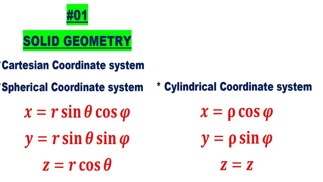
Added:Basic understanding of 3D Cartesian coordinate systems (X, Y, and Z axes) and spatial geometry.
Familiarity with fundamental 2D geometric concepts such as lines, circles, angles, and dimensions.
General computer literacy, including installing software, file management, and using a three-button mouse for viewport navigation.
An introductory understanding of what Computer-Aided Design (CAD) is and its role in product design and manufacturing.
Mastering the Part Design and Sketcher workbenches to create fully-constrained parametric 3D models.
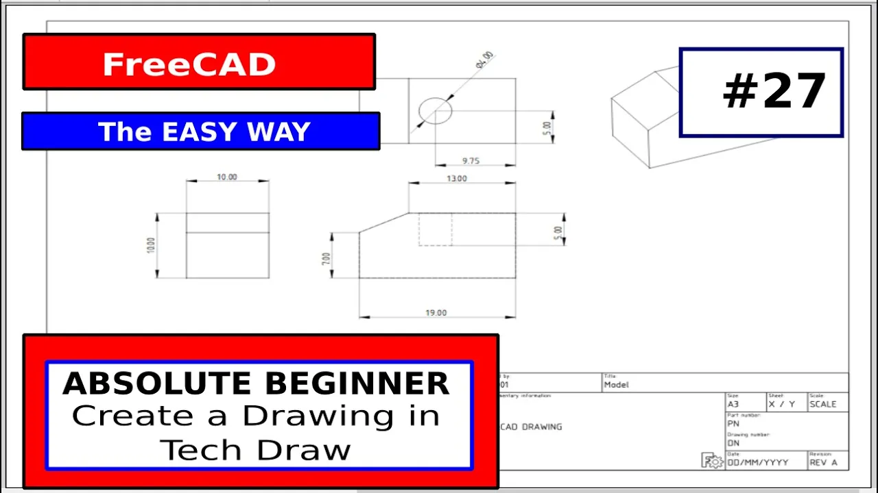
Generating 2D technical drawings and blueprints from 3D models using the TechDraw workbench.
Learning how to assemble multiple parts into complex mechanisms using assembly workbenches like Assembly4 or A2plus.
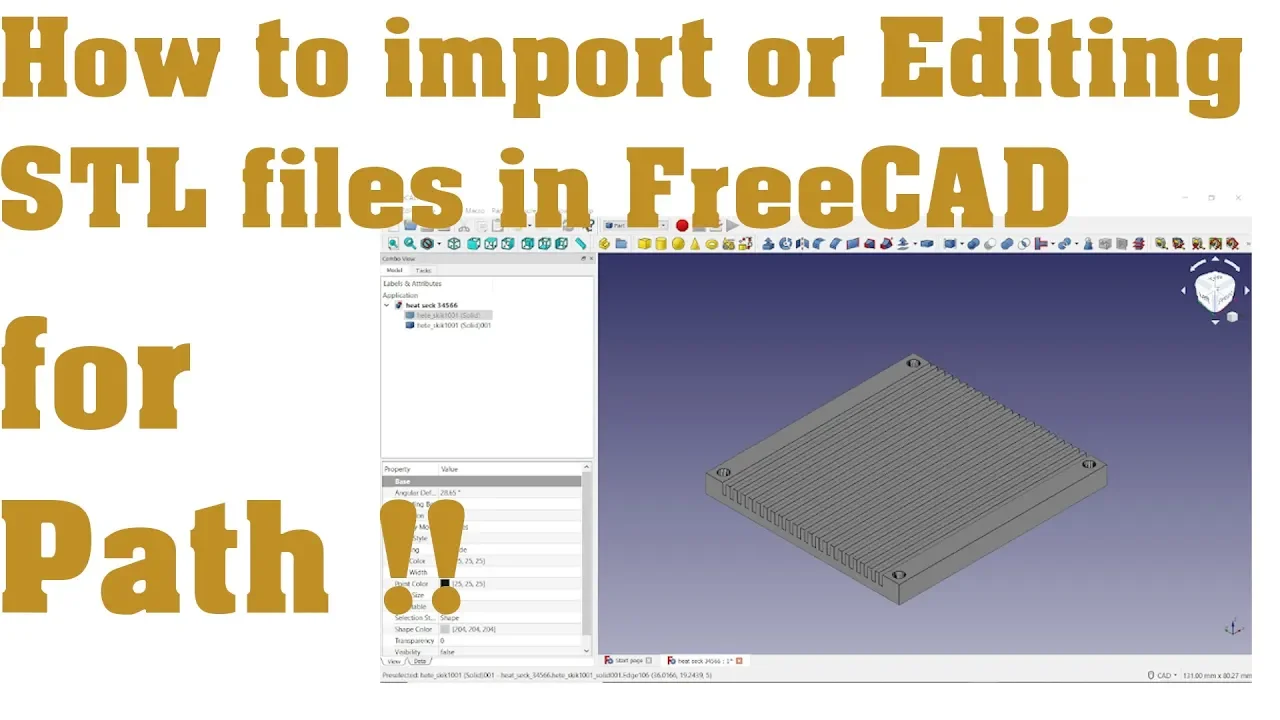
Preparing 3D models for physical fabrication, such as exporting STL files for 3D printing or using the Path workbench for CNC machining.
Utilizing spreadsheets and mathematical expressions to drive parametric dimensions for design automation.
155.5K views4.2Klikes29:00Original Release: 2024-12-16
freecad is one of the few truly free and open-source computer AED design packages out there it's capable of creating complex designs but it's not without some bugs and pitfalls in this 10p part series I'm going to help you get up to speed with freecad so you can start designing your own Parts before we jump into the specifics of using the program I want to talk about why you should use freead and cases where something else might be better let's get started here is the syllabus for the course in this episode I'll talk about the pros and cons of using freead over other CAD packages I'll end with installing freead and giving a tour of the interface to help you understand the layout and where to find things next we'll dive into the basics of creating an object using the part design workbench this workbench relies on the more modern Paradigm of creating feat fees from sketches we'll then talk about creating designs that interface two separate bodies in the same document even though you can use freecad for Designing just about any mechanical part I'll assume that you're mostly interested in using it to make custom 3D printed Parts as a result I'll show you how to design for and use heat set inserts as they are incredibly popular for holding 3D printed pieces together after that we'll look at creating patterns from features and using Boolean operations to fuse or cut parts to create more complex shapes revolutions pipes and lofs can make it easy to create other complex shapes up to this point we'll focus mostly on the part design workbench in freead while it's a great way to get started making most basic and intermediate shapes it has some limitations when it comes to creating curved surfaces as a result we'll need to look at the curved shapes workbench which is a third party add-on that makes working with Lofts along guide rails much easier we'll also look at the curves workbench for doing organic shapes finally we'll examine the assembly's workbench to see how parts fit together and then the finite element method or FM workbench for simulating stress and failure points on designs as I mentioned much of this series assumes you'll be interested in designing parts for 3D printing because of that I'll 3D print most of the parts you see in this series so you can see how they come out if you have access to a printer you are also welcome to print the parts as seeing them come to life in the physical world is always inspiring if you do not have access to a printer that's okay too you can still follow along with the series to learn how to use freecad which is great for even non 3D printed designs I like to learn a little bit about the history of tools I'm using and compare it to other tools on the market but if you're not interested feel free to skip ahead to the part where we install the software or to the next episode episode where I'll show you how to design a part the history of computer AED design is almost as old as the electronic computer itself in the 1950s computer scientist Douglas Ross coined the term CAD to describe using interactive graphical displays inspired by radar equipment to help debug software and display flowcharts and circuit diagrams then in 1964 daak 1 was released which was one of the earliest forms of commercial CAD Pro programs Patrick hanra a lead developer on Dak one is often considered to be the father of CAD by some accounts 70% of all 3D mechanical CAD software today can trace their Roots back to henra's code Lots happened in 30 years to further the state of commercial CAD but let's shift our Focus to freead in 1993 mattra data Vision a French company released the computer AED software for computer AED design and Engineering or Cascade which provided the foundational layer for the uclid cad package around the time mattra data Vision was acquired by Doo system in 1999 they open- sourced Cascade as I suppose it wasn't needed for Doo's solid works Jurgen Regal who was working for Daimler in 2001 and had been building software on top of open Cascade started working on an open- Source CAD software that he called freead his colleague verer Meyer joined him as soon as the project was announced together they released the very first version of freecad in 2002 a few years later York Von hover joined the team from there we see the Sketcher workbench added in version 0.10 and the part design workbench added in version 0.11 while freecad consists of many different workbenches as we'll see later these are the two most important ones that you'll interact with regularly especially as you're learning the software in 2015 Jurgen left the core team and is no longer active on the project then in 2019 Abdullah bar sliptonic and Wanderer fan joined the core Dev team and here we are today in 2024 while the development version of freead is 0.22 it will likely become the first official version 1.0 release along with that the community submitted various logos for a brand refresh and this new modern logo by Sebastian B us was chosen while this is all well and good why should you even consider using freeat over other CAD packages the reality is that like Linux a free and open-source CAD package has its advantages and disadvantages on one hand it's free to use and you have complete ownership of all your work even for commercial purposes on the other hand it's not as fully featured nor as intuitive as most commercial packages then it's prone to crashing before we dive into evaluating a few different CAD packages we need to understand what parametric modeling is most 3D CAD programs consist of combining or defining shapes to create one or more complex solids with direct modeling you define shapes and dimensions quickly without worrying about constraints or how they'll affect things down the road parametric modeling on the other hand involves specifying parameters for constraints and dimensions these might be dimensions on a sketch on a shape or defined elsewhere in say a spreadsheet you can then reference these parameters to set exact constraints elsewhere also most modern CAD software will let you update parameters you set earlier and it will simply update the design without hopefully breaking everything with that in mind we'll evaluate these programs using six basic criteria and note that this data was collected in August of 2024 when I recorded this video the first is cost for personal use which means it can be used for Hobby and educational purposes with commercial tools there is usually a limit on how much money you can make from something designed with their free or lowcost version it's often around $2,000 per year we'll also look at the minimum cost for going to the commercial version that lets you actually start a business using the tool this won't include any optional add-ons or additional seats for the license but most commercial commercial licenses unlock additional features we'll see if the package can handle parametric modeling or if it relies on Direct modeling I'll also mention open source here as it's an important aspect of freecad Open Source usually means that the program is developed by a community of programmers may or may not have funding and you can expect certain things like the interface might not be that great and the software might not be super stable however it means that you can read and modify the code and it's usually easier to submit bugs to the core Dev team next is what operating systems the software runs on and if it runs locally or in the cloud finally we have the number of features and how easy it is to use the software both of these are incredibly subjective based on my limited use of the application and stuff I read on the internet so take it with a grain of salt first up is freecad which we'll use as our standard it's completely open source and free to use even for commercial purposes it'll run on Modern versions of Windows Mac OS and Linux it's actually a fairly complete 3D CAD package with enough features to do complex designs however the interface is not particularly intuitive and the error messages can be less than helpful next up is the industry standard solid works they have a personal version that costs $48 per year which is not bad however if you want to make any significant money off your designs you'll need to pay for the fully featured commercial version which starts at around $4,000 plus an annual subscription of about $1,500 obviously it's not open- Source but it can do parametric modeling oh and it's Windows only the program runs locally and you have the option of saving files to their cloud storage system solid works is the Juggernaut in the industry and has just about every feature you can think of including Advanced assembly simulation and Manufacturing workflows it's easier to use than freecad but it still has a pretty steep learning curve solid Edge is another commercial CAD package that competes directly with solid works they have a free community addition and their basic subscription is about $1,000 per year with a wide range of possible add-ons otherwise it competes almost exactly with solid works it's Windows only runs locally and offers option cloud storage I don't have experience with it but people claim it's similar to Solid Works in the amount of features and ease of use from my understanding it's not as popular as solid works though next we have Autodesk Fusion which was previously called Fusion 360 this is probably the most popular mechanical CAD package among hobbyists right now they have a free version for personal use and the commercial version is $680 per year which is honestly very reasonable for what you you get it also supports parametric modeling is closed source and can run on Windows and Mac OS sorry no Linux feature-wise it's close to what solid works can do in terms of modeling but it lacks a few Advanced simulation workflows the program runs locally but you're forced to save your work in the cloud you can export your data to local files if needed it's also praised for being intuitive with a lower learning curve than both freead and solid works Tinker CAD is is another Autodesk product that aims to make 3D modeling easy for mostly educational purposes it's completely free but the terms of service claim that Autodesk can use your work in any way they want which includes Su licensing it to make money by default Tinker cat is built around a direct modeling Paradigm but recent additions now allow you to Define constraints with code blocks scripts making it somewhat parametric Tinker CAD is close Ed source and runs in the cloud which means you just need an operating system that supports a modern browser it really only has one basic workflow for modeling shapes by combining simple shapes like cubes and spheres if you need more advanced features Autodesk would prefer if you move to something like Fusion it is however extremely easy to use I think I learned Tinker cat in about 2 hours while it's great for educational purposes you're probably better off with one of the other more professional tools for complex work then we have onshape which is a relatively new player on the scene like Fusion they have a free version but all your projects are made public in the cloud which means anyone can see and access them PTC the company behind onshape has rights to use your public projects much like how Autodesk can use your projects from tinkercad the commercial version starts at $1,500 per year it supports parametric modeling is closed source and runs in the cloud while I haven't personally used on shape most people say it has almost the same amount of features as fusion and is about as intuitive to close out this comparison let's look at two other popular open-source offerings first is blender which gets a lot of attention in the animation and Video Game World the workflow in blender is organic and better suited for things like animating a 3D character it's more like sculpting and people use it a lot for creating models and Miniatures that can be 3D printed so while it's free it's not really parametric without some third party add-ons like freead it's also open source and runs on most of the popular operating systems there's no Cloud option either while blender is feature Rich most of its features are for character design and animation which don't apply to most of our mechanical needs the interface has gotten much better than when I tried it many years ago but the learning curve is still pretty steep finally there's open scad which is a parametric modeling software used for making mechanical Parts however the workflow is completely different from other CAD packages as it uses a programming language to define the parts this scripting aspect makes it fully parametric like blender and fread it's free and runs locally on most major operating systems you can do a lot with it but considering you can run open scad in freecad as a plug-in I'll say freecad has more features it can be difficult to learn as you need to know how to program if you're comfortable programming and learning new scripting languages feel free to add a couple of stars for ease of use there are many more CAD programs out there that I did not list as I mostly focused on the popular ones I hear about in my engineering and hobbyist circles as you can probably guess freecad is a perfectly capable parametric modeling application but it's lacking some of the advanced features of paid tools the learning curve can also be a bit steeper however it's free and you own all of your work the development team has also made significant improvements in the last couple of years which puts it in a good position to compete with other paid tools the biggest Improvement has probably been fixing or at least mitigating the topological naming problem this is an issue in almost all modern parametric CAD programs when you create a shape or feature the program will assign unique names to all the points edges and faces to that feature we'll create a few features stacked on top of each other don't worry about trying to follow along right now I'm just going to demonstrate this error notice that this is freead version 0.21 which I won't be showing in the rest of the series now if we change one of the earlier features within the same bounds say making this rectangle a little bigger the model updates without a problem however if we go over the Border freead needs to make new edges and faces on the underside to make this model work as a result the modeling solver breaks you either end up with the topmost feature on some face you didn't intend or you get the dreaded recompute failed message freecat doesn't have the most helpful error messages and this doesn't tell me what failed with experience and understanding the sub icons in the treeview I know that my model broke sometime around pad 002 to fix this you'd have to go back to earlier steps and redraw everything I wasted many hours trying to work around the topological naming problem most modern parametric CAD programs have also fixed or at least mitigated this problem the latest version of freead 22 which will likely become the official 1.0 release includes a fix for the topological naming problem it's not a complete fix as I still run into issues sometimes but it's it's much better than before now when I try to modify the middle sketch the model does not break like before because of this I'll be showing version 22 and recommend that you use it if you use a later version that's okay too just note that some of the tools or buttons might be in different places or have different names and icons I'll be using the latest weekly build my hope is that version 1.0 is released when this video comes out and you can just use that but know that version.22 should be close enough I recommend some optional tools if you want to get the most out of this series the first is a set of calipers which are useful for taking precise measurements of objects that we want to replicate or interface with next is a 3D printer you don't need one but most of the videos in this course focus on modeling objects that you can then easily print there's something fun about actually holding the physical object you designed I highly recommend checking out my introduction to 3 printing videos if you'd like to get started using a 3D printer I hope that this has helped you understand why you might consider using freead over paid options or why you might need to go with a paid CAD package instead if you still want to learn freead I'll show you where to download the latest build and how to navigate in the rest of the episode in the next episode we'll design our first part head to freec cad.org which has gotten a nice makeover in the past couple of months click on download assuming you using one of the popular op operating systems you can download the installer from this page if not well freead is open source and you can always build it from source code when I filmed this version 21 was still the official release by the time you watch this video I'm hoping that these installers will be for version 1.0 note that some of the features you see in this series might be a little different or the icons might change if these links are not for version 1.0 or later then you'll want to run one of the weekly builds scroll down and click on the weekly builds link find the package for your operating system and download it that's windows for me unzip it somewhere on your computer this might take some time for mac and Linux you might need to run an installer when that's done navigate into the freecad folder and find the bin folder in there find the freecad executable feel free to make a short cut to this file somewhere on your desktop or start bar for now just doubleclick it to start freecad once again this process is probably different for mac and Linux but it should be equally straightforward if Windows yells at you that the app is unrecognized Click more info and click run anyway freead should load it will ask you to select a language unit system navigation style and theme pick your language and leave the unit system at the default metric system for navigation I really like Tinker CAD style as I find it to be very intuitive so I recommend using that I'll also show you how to change these later select a theme if you wish and then click done like most modern graphical interfaces it will try to suggest what to do next I recommend just ignoring these suggestions as I'll walk you through the process of creating documents and parts from scratch I mentioned earlier that freecad is a collection of workbenches a workbench is in turn a collection of tools buttons and interface options free by default puts us in the part design workbench which is the recommended workflow for newcomers to create 3D designs take note of the buttons and menu options we'll slowly go over most of these in the coming episodes but just pay attention to what happens when we switch workbenches in the top bar of freead you will find the workbench selection menu click to drop it down to see the various workbench options these are the default workbenches that come with freecad and you can install thirdparty workbenches which I'll demonstrate in later episodes there's a lot here so this can be somewhat overwhelming if I click on part you'll notice that the buttons and menu options change as I have switched over to the part workbench part is just another way to create 3D objects it was added in the early days of freecad before part design so it's often considered the Legacy or old school workflow but it still has some uses it relies on the old older constructive solid geometry method which involves adding and subtracting simple shapes like cubes and spheres to create more complex Parts Sketcher is another popular workbench used to make 2D drawings that can be used in 3D designs for the majority of this series will'll Focus on two workbenches part design and Sketcher these workbenches operate in tandem to help you create 3D objects in later episodes when we start making more advanced shapes or putting Parts together in assemblies we'll explore other workbenches for now select the part design workbench click on the new document button this creates a document object in the tree view on the left side a document can store multiple Parts containers bare sketches and so on when you save your work everything under this document object gets saved as a single freecad project file you can have multiple documents open at once but I usually prefer to close all but the one I'm working on to keep this tree view clean notice that I can click on a document to activate it and the title will become bold you can rightclick on a document and select close document to remove it from the workspace click create body you can also find this command under the part design menu option this creates a body object in the current document in the part design workflow a body is a collection of operations needed to create a single continuous shape of any complexity we'll create a simple design in a body in in the next episode notice that the body is highlighted with light purple that means this body is the active body in the document when I create sketches or features they get applied to the current active body if I add another body the new one will become the Active Body in a couple of episodes we'll start working with multiple bodies in the same document so it's useful to know how to switch between active bodies right click on the non-active body and select Active Body to to switch to work on that body notice that we have an origin under the body that is grayed out that means that particular object is hidden from the main 3D view rightclick on origin and select toggle visibility you can also select the origin object and press the space bar you should see a set of axes and planes appear in the main view note that the body and the feature or object must be set to visible to see them in the viewer if I hide the body with the origin visible the origin and anything else under that body will disappear this continues to bite me to this day if something isn't showing up in the viewer make sure that both the body and the feature are both set to Invisible right click on the second body you created and select delete you can also press the delete key most objects and features you see in the tree view can be deleted this way right click somewhere in the viewer and move your mouse around while holding down the right Mouse button this allows you to rotate the view which is incredibly useful when making 3D Parts the Little Red Dot that appears shows you where you clicked and the camera will rotate around that point if you hold the middle Mouse button and drag the mouse the camera will pan you can also Zoom with the mouse wheel this combination of rotate pan and zoom is all you need to set your camera to any angle and position if you do not like this control scheme go to edit preferences notice that in general you can set the unit system should you need to change the default for freead make sure it's set to metric as that's what we'll use for most of this course in my experience you usually need to restart freead after setting the unit system go to display navigation click the drop down menu by 3D navigation these are the available schemes I happen to like the Tinker CAD style so I'll leave it at that it's similar to the navigation scheme in my slicer program but sometimes if I'm working on my laptop with no mouse I'll switch it over to a touchpad click the mouse button to see the scheme close out of those menus you can left click to select Parts faces and lines in the viewer this will be necessary when we start manipulating sketches and features later in the top right you'll find the navigation Cube you can click on various parts of the cube to set the camera to view that particular face this includes edges and Corners as well the arrows let you rotate the camera 45° in that particular direction the little Cube icon gives you the option to change the perspective you can also find these options in the view menu orthographic is the normal view style for most CAD programs there is no perspective so objects farther away appear to be the same size as those closer to the camera this is very helpful when trying to line up different features in a 3D shape if you'd like to enable perspective you can click on the perspective view this can be useful to see how an object might look in real life but usually I leave it off when designing Parts the very basic flow of Park design is to create a two-dimensional sketch and then create a three-dimensional feature from that sketch as I showed in the topological naming problem demonstration we first click on a sketch below the tree view pane you should see the tasks pane change and ask you where to place the sketch notice that most of the workbench buttons are grayed out if you ever notice that you can't do something in a workbench first check to see if there's something in the tasks pane either finish the task or click cancel and the buttons should no longer be grayed out this also continues to bite me for now let's create a sketch and click on the XY plane note that you can either select the plane in the tasks pane or in the viewer if you select it in the viewer The View will rotate to face that plane also notice that the workbench automatically changes to Sketcher and our buttons are now different from here we can create a basic shape like a rectangle click the create rectangle button and draw the shape anywhere in the main view notice the rectangle Icon by our mouse cursor this shows that we're still in the create rectangle tool mode either right click or press the Escape key to exit the tool for a normal design you'd want to define the dimensions or set the constraints of this sketch before moving on we'll cover that in the next episode for now just click close in the tasks painting notice that we return to the part design workbench with the sketch selected in the tree view click the pad button this has the same effect as creating an extrusion from our sketch leave the default parameters and click okay in the viewer you should see that we've created a very simple box out of our sketch in the tree view you can expand the pad operation to see our sketch in part design we create a set of operations or features that are computed in chronological order to make up a single contiguous body don't worry if that didn't make much sense right now you'll get a feel for it as we start making Parts later if you doubleclick the sketch you can edit it now if I drag one of the sides to be longer and click close you'll see that the pad operation automatically updated with my sketch this is the basics of parametric modeling we can set parameters in our sketches or 3D features and the system will automatically update when we change those parameters we'll dive more into this later don't worry about saving this document I just wanted to show you the basics of the part design workflow so that you're somewhat familiar with it for the next video I hope this helped you understand a little about the various CAD offerings and how to somewhat navigate in freak CAD in the next episode we'll actually make our first part and I'll give you a fun challenge at the end stay tuned [Music]
Up Next

5:18
How to Make a Hydrogel: Polymer Science for Kids | Biomedical Engineering
@jfreemn
30.3K views•2015-11-02

12:54
Triumph of Orthodoxy Icon: Byzantine Art & History Explained
@BenCallan
2.1K views•2024-08-06

9:49
FastAPI vs Flask vs Django: Choosing the Right Python Web Framework
@TechWithTim
302.5K views•2024-05-26

1:42
Game of Thrones Opening Credits: A Cinematic Analysis
@gameofthrones
46.3M views•2011-04-18
Related Study Plans & Knowledge Roadmaps
Structured learning paths in General & Interdisciplinary Studies
general-studies
Elevator Engineering: History, Physics & Cities
01From Hoists to Safety Brakes: The Dawn of Vertical Lift
02Hydraulic vs. Traction: The Engineering Physics of Elevators
03Modern Speed, Safety, and Algorithms
+ 2 more learning modules
12h5 modules
Explore Roadmap
general-studies
Rubber: Material Science, History & Geopolitics
01Origins of Natural Rubber & Mesoamerican History
02The Chemistry of Natural Rubber & Vulcanization
03The Geopolitics of the Rubber Boom & Colonization
+ 2 more learning modules
12h5 modules
Explore Roadmap
general-studies
Containerization: Evolution, Logistics & Trade
01Ancient Trade & Bulk Cargo: Amphorae to Barrels
02The Industrial Revolution & Cardboard Packaging
03The Containerization Revolution: Malcom McLean
+ 2 more learning modules
12h5 modules
Explore Roadmap
general-studies
Textile Tech: Evolution, Labor & Global Impact
01Pre-Industrial Textiles: Handloom & Cottage Industry
02Mechanization: The Spinning Jenny to the Power Loom
03The Factory System & Global Labor Transformation
+ 2 more learning modules
10h5 modules
Explore Roadmap