






















When designing custom 3D printed electrical enclosures for mass production, prioritize structural integrity by making standoffs as thick as possible and using chamfers instead of fillets to eliminate orientation requirements and prevent breakage; optimize manufacturability by avoiding flat printing orientations, minimizing bed contact through chamfered corners, eliminating sharp internal edges, and considering PCB inset designs over traditional standoffs to reduce support material and improve print quality while enabling easier assembly and ESD-safe material options.
Designing Custom 3D Printed Enclosures: A Guide
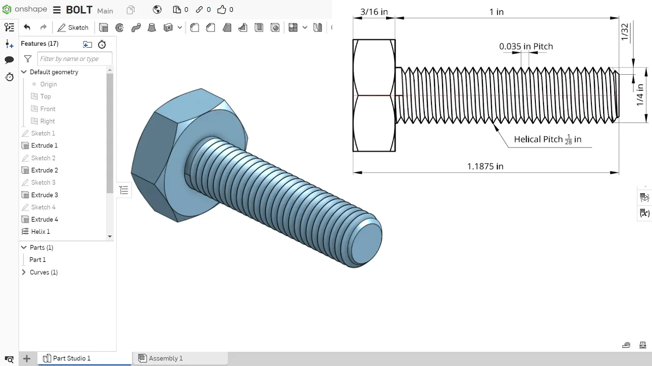
Added:Basic proficiency in 3D Computer-Aided Design (CAD) software, such as Autodesk Fusion 360, SolidWorks, or Onshape.
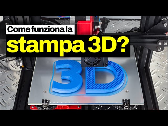
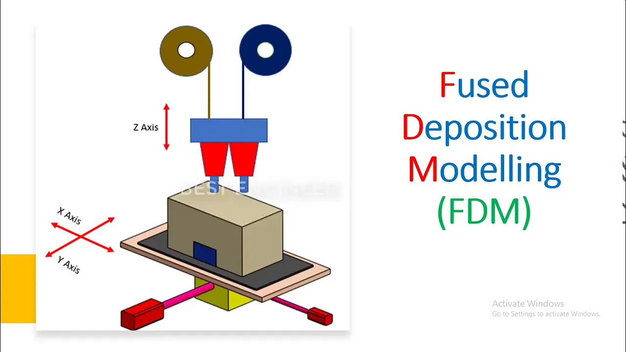
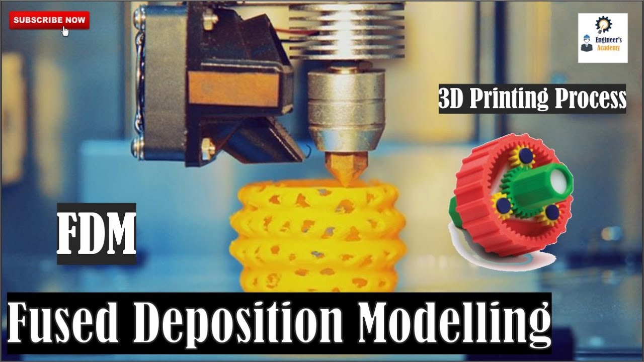
Fundamental understanding of 3D printing technologies, specifically Fused Deposition Modeling (FDM), and how layer-by-layer fabrication works.
Concept of dimensional tolerance and clearance fits, which are essential for ensuring physical parts assemble together properly.
Basic familiarity with electronic hardware components, such as PCBs (Printed Circuit Boards), ports, switches, and power connectors.
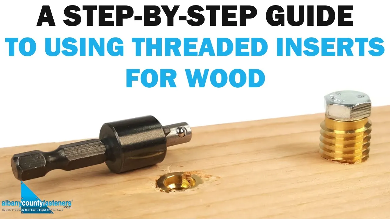
Advanced enclosure fastening techniques, such as designing snap-fit joints, living hinges, and incorporating brass threaded inserts.
Thermal management and cooling design, including the strategic placement of ventilation slots, heat sinks, and active cooling fans.
Designing for Ingress Protection (IP) ratings, which involves integrating gaskets and seals to protect electronics from dust and moisture.
Design for Manufacturing (DFM) principles for scaling production, specifically transitioning a 3D-printed prototype to injection molding.
61K views1.6Klikes11:59Original Release: 2023-03-31
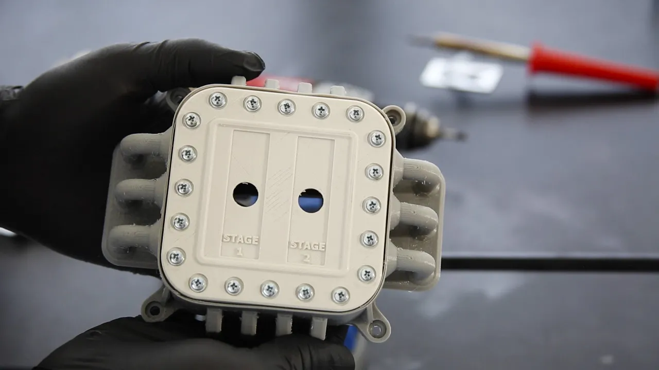
hello everyone and today what we're going to do is we're going to go through and talk about how to design a 3D printed electrical enclosure now you probably are familiar with electrical enclosures from the past they're just a plastic box and generally they have some sort of sprues inside of them or some sort of standoff in order to mount the chip inside of the Box uh the benefit of the 3D printed uh enclosure is that it can be fully custom and customized to the box you can make it oddly shaped on the outside you can give it organic curves you can give it some textures and of course you can do simple things like Give It Holes exactly where you want them and label exactly how you want them something like this which is a really big benefit because you get a fully custom solution which is not always that easy to do but the challenges with a 3D printed enclosures that very often they are not designed for 3D printing people designed for injection molding when they're making one of these and that's an incorrect place to start so today I'm going to show you kind of the key features of how to make a 3D printable electrical enclosure that will actually be good and give you those details so you can use them in your own designs so right here uh This is Gonna this is just a general dimensional box of some imaginary PCB that we're gonna put inside of here and these four uh slots or holes right here Mark the places of these standoffs where the chip has to screw into the standoffs of the box so the first thing we're going to do is the simplest way to address this is to just make a really thick standoffs a lot of people try to make these really thin you do not want them real thin you want them to be very um as thick as you possibly can because the the more material you can put inside of there the more structurally sound it is and you don't have to worry about putting in any sort of extra support or worrying about like 3D printed Parts snapping off if a technician tweaks it with a screw of some kind or a screwdriver let's extend those out um right there okay so we have these standoffs and again making them as thick as you possibly can but generally you would start running into the leads or the uh the solder points on the bottom of the PCB however with these parts they're not done you don't want just that thickness you also want to make sure to use a chamfer not a fill it but a chamfer cool there's a fillet should be able to do a chamfer here there we go but you want to use a chamfer because you can see how it has this nice rise so that there's no orientation requirement with it at all so you can print this box in any orientation there is no way that the standoff will break off and using these types of features don't actually add really that much material because you're just adding basically extra honeycomb on the inside which might add a gram of material but it's not significant especially for the structural benefits that it gives as far as designing this hole you can either design it to be a screw straight in and self-tapping or you can design these holes to be heat set and talk to your application engineer about which one would be best for your particular solution if you want to use heat inserts they can give you kind of dimensional info of how to design those but you can see with like this fillet here it would the problem with fillets is that they come down to horizontal so you would start to have overhang right here if you were printing this box on its side but we'll get back to that a little bit later right here another option and way of doing this is to actually go ahead and design in ribs we're going to continue to look at it from the side here as if it's printing in this orientation in that case you would want some kind of a rib like this and and you can make it tangential to the thing if you want to but I'm just going to go ahead and go like this and we're going to take that up distance to the floor just like so and then you have that rib that can sit there it could go all the way to the outer wall so that again you get more support and more structure or here in this case I'm just going to chamfer It Off and you have again a nice little rib and chamfer in there take it to however far end you want to go but make sure you have a lot of surface and that will be fine but again mainly with the standoffs it's just whenever you can add volume to a part with a 3D printed part you want to because it gives you so many new structural benefits and generally improves manufacturability because we don't have any overhang problems so there we go those are kind of the four main ways of Designing the sprues but what about the Box itself so we have this box you could probably live with it as is but we want to make this highly manufacturable we want this to be as affordable as possible to create and for that you definitely don't want to print it laying down flat like this to where this broad side is against the bed because that would be dramatically increase the cost and wouldn't really give you very many benefits printing on this side is better um but it still could be sticky and this is a side that the customer or client or end user might be able to see again so you want to minimize faces that are in contact with the bed so what we're going to do is we're actually going to go ahead and just chamfer these outer corners and I go deeper into why this is so important uh in another video but you want to make this chamfer just as big as you possibly can too I'm going to go all the way for 10. because even though that thin corner is there it's going to be a very strong thin Corner oh that's a special chamfer that was a two distance one I want it to be equal distance of seven there we go um but now we have this corner the other thing to do is you don't ever want any sharp Corners inside of the part at all so we're going to go in here and we're gonna fill it actually I'm going to save myself some steps I'm going to fill out these Corners first and save myself a couple of clicks don't want that face and again make the fillets as big as you possibly can I'm going to go ahead and just go for the five that I started with because that's a nice happy medium but again if your PCB needs to fit in there stringently make it whatever fillet you're able to and then of course fill at the bottom just a little bit here I'm going to give it five two just to make it All Uniform because again down on the bottom it doesn't really matter with all of this I'm actually going to show you actually one other option let me export this real quickly okay and we're back uh we're gonna go ahead and suppress basically all the stuff that I just did because there's another way to get it done another option is to actually just outline the leads of the board itself and what I mean by this is that you can design this in here again you want a few Islands or as few individual features as you possibly can so I'm going to go ahead outline all of these I'm just going to kind of eyeball it here I'm not going to give them well I'll give them set Dimensions what the heck it's not that hard just like this because these are going to be the holes just like so but then uh if the leads are not inside of there an even better way of getting this done is to take something like this and go here then from here to there and then from here to there and then again if you have like a weird um the leads or the solder points on the bottom of the board if they have a special construction of some kind you can go through here and make some kind of a random shape that moves out around and whatever it happens to be I'm going to let that kind of be that way even though it doesn't seem very technical but it's fine because maybe you have some leads sticking way out here and it'll make more sense here in a moment once I get this done I'm going to make it a little more symmetric there we go and then we will basically extrude this backwards to whatever your highest lead is and I'm going to take it backwards five oh we're just gonna take it backwards three but you can see now that that plate that PCB is basically mounting against a solid surface and you could actually even run ribs across this so that the PCB is really well supported especially if there's an is in a high vibration area that way it's no longer on standoffs it's basically embedded into a custom uh inset for the PCB and this is also really great because again there's no features that can snap off get broken or in manufacturing somebody's ruin these are really good for heat inserts and again that's just another way of mounting the PCB so that the solder points are able to go Inward and you don't bend the board so it's able to mount flesh against the screw holes but still have space backward there for the lead sticking out so let's go ahead and Export this and I'll tell you what those chamfers are so special about here okay so the first thing we're going to look at is that first enclosure that we made obviously it's importing here normally like I said you never want to print an electrical enclosure like this because it just creates a opportunity for the standoffs to break off um even if they are like this and again this is not ejectable the machines remove these parts from the bed and if it has a very high surface area in contact with the bed it could cause an issue and it can also cause defects throughout the print so the other option is here on the edge like we stated before but again this might be a customer facing space so you don't really want that so actually the best option is to print it like this now there are no direct overhangs you can see here that because we use this chamfer right here that's standoff is fully supported unlike this one up here and actually let's go ahead and take a look at that real quick um I'm going to go ahead and do everywhere and make that a little bit better here that way I can show you if this was just if this is a standard type of standoff then we would have to generate this internal support material this blue stuff right here that creates all kinds of issues for us because it's just extra material that has to be removed and thrown away and doesn't actually do anything functional so what we're going to do now is now we've got it set up like this we ideally would have our ribs oriented in the correct direction so in order to avoid confusion I'm going to go ahead and rotate this all the way around like this that way this rib is actually helping and you can see the fillet again has this overhang that would cause some support but this chamfered one up here is perfectly clean the outer walls don't have any problem and the only outer surface that'll look a little bit different is the single bit of touch right there the other option you can possibly do is actually chamfer this lower Edge so that it leans back and something like that would look a bit like this and again look at that other video but this has a problem because now the center of the gravity of the part is not over Center so it can cause disconnection for the bed so it's not the greatest option if you can you want it to all be symmetric just like that so you can see how that's going I'm going to take uh take a look at the material used in the print time on this as it comes out it's printed in a low resolution and low infill because again this part should be fairly efficiently made eight hours 117 grams that's quite a bit but let's pull in this other one that's the inset Style let that slice and sewage saved some time and some material there mainly because we don't have the sprues which adds a bunch in so this isn't a huge benefit but you can see that it'll come out so much Slicker and it'll be so much easier to place the PCB because you basically have this inset acting as a finding feature so that the leads themselves could align with this Outer Edge and then Force the PCB into position that way your technicians can easily set those screws the problem with this inset format is that you have to make this back wall really thick but it is good if it's a side mounted part or if you're allowed to have a hole in there or anything else like that if you wanted to you could put a hole in there so that people can poke out the PCB you can have a row of holes you can have a new outlet pop out the side and if you're thinking about the end process of using fdm 3D printing to produce these you can get ESD safe materials it's much more affordable than mold in most time and anytime you want to you can update the design for whatever your new PCB might be because pcbs can change every day but the molds if you had this molded cannot change all the time or they're exceptionally expensive to change so hopefully that shows you how to design custom 3D printed enclosures and hopefully you learned a little bit about how to design for manufacturability with 3D printing have a great day everybody
Up Next

8:08
Magnetic Nanoparticles in Biomedicine: Clinical Applications Explained
@PhysicsWorld1
9.2K views•2009-11-12

12:54
Triumph of Orthodoxy Icon: Byzantine Art & History Explained
@BenCallan
2.1K views•2024-08-06

9:49
FastAPI vs Flask vs Django: Choosing the Right Python Web Framework
@TechWithTim
302.5K views•2024-05-26

1:42
Game of Thrones Opening Credits: A Cinematic Analysis
@gameofthrones
46.3M views•2011-04-18
Related Study Plans & Knowledge Roadmaps
Structured learning paths in General & Interdisciplinary Studies
general-studies
Elevator Engineering: History, Physics & Cities
01From Hoists to Safety Brakes: The Dawn of Vertical Lift
02Hydraulic vs. Traction: The Engineering Physics of Elevators
03Modern Speed, Safety, and Algorithms
+ 2 more learning modules
12h5 modules
Explore Roadmap
general-studies
Rubber: Material Science, History & Geopolitics
01Origins of Natural Rubber & Mesoamerican History
02The Chemistry of Natural Rubber & Vulcanization
03The Geopolitics of the Rubber Boom & Colonization
+ 2 more learning modules
12h5 modules
Explore Roadmap
general-studies
Containerization: Evolution, Logistics & Trade
01Ancient Trade & Bulk Cargo: Amphorae to Barrels
02The Industrial Revolution & Cardboard Packaging
03The Containerization Revolution: Malcom McLean
+ 2 more learning modules
12h5 modules
Explore Roadmap
general-studies
Textile Tech: Evolution, Labor & Global Impact
01Pre-Industrial Textiles: Handloom & Cottage Industry
02Mechanization: The Spinning Jenny to the Power Loom
03The Factory System & Global Labor Transformation
+ 2 more learning modules
10h5 modules
Explore Roadmap