
![#2 Instrucciones Básica [ pinMode, digitalWrite, delay ] - Curso Arduino 💻](https://i.ytimg.com/vi/dwet3or5rmQ/maxresdefault.jpg)

















![Kickstarter Crap - Rocket Skates [Smart Wearable Mobility]](https://i.ytimg.com/vi/q-MAfzGrPl8/maxresdefault.jpg)

A self-balancing robot functions as an inverted pendulum that uses PID (Proportional-Integral-Derivative) control to maintain equilibrium: the proportional component responds to the current angle error, the integral component accumulates past errors to eliminate steady-state drift, and the derivative component predicts future behavior based on rate of change; the control loop continuously adjusts motor speed based on the robot's pitch angle, with the setpoint determined by both onboard sensors and remote input, while the NRF24L01 module enables wireless communication between the remote controller and the robot's Arduino-based control system.
Build a Self-Balancing Robot: Remote & PID Control (Part 3)
Added:Basic Arduino programming and electronics, including working with microcontrollers, GPIO pins, and writing control loops.
The fundamentals of PID (Proportional-Integral-Derivative) control theory, specifically how error feedback regulates a system.
Working principles of an Inertial Measurement Unit (IMU), specifically reading data from accelerometers and gyroscopes.
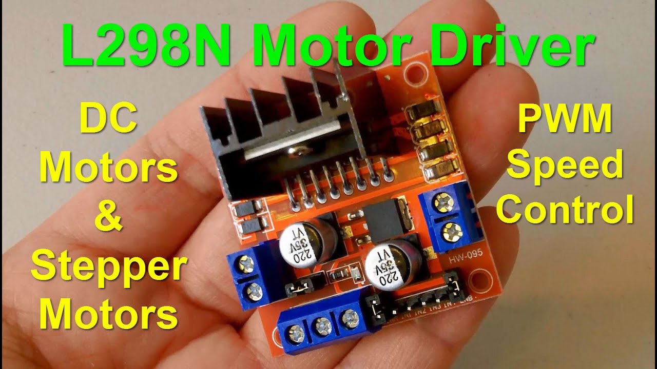
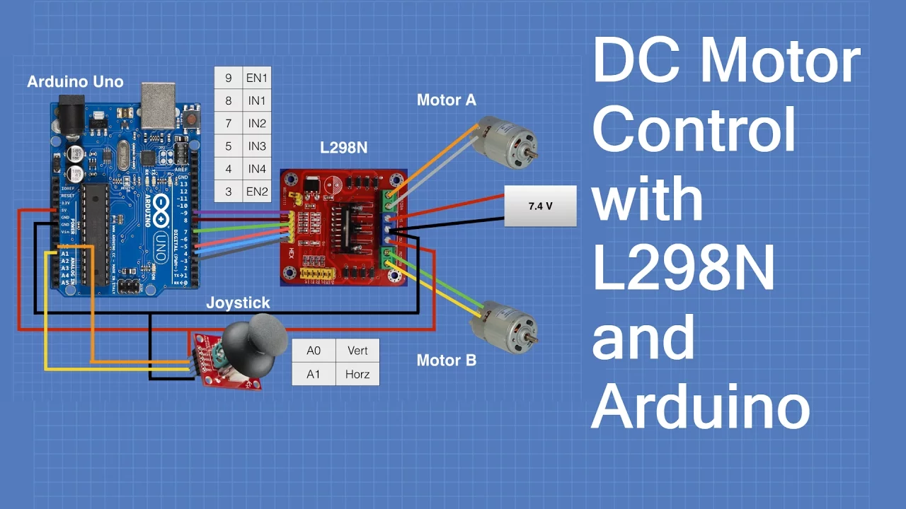
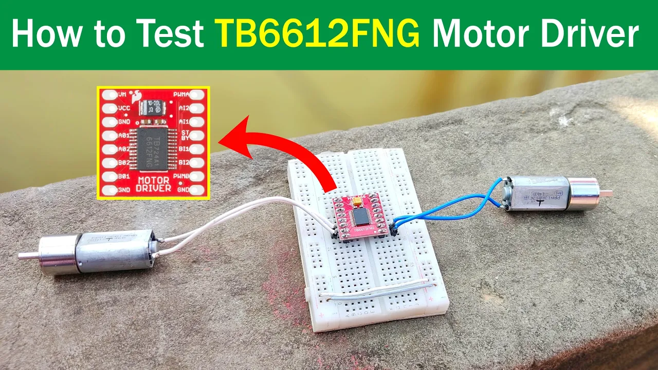
DC motor control basics, including Pulse Width Modulation (PWM) and using H-bridge motor drivers (e.g., L298N or TB6612FNG).
The physics of an inverted pendulum system, representing the basic mechanical model of a self-balancing robot.
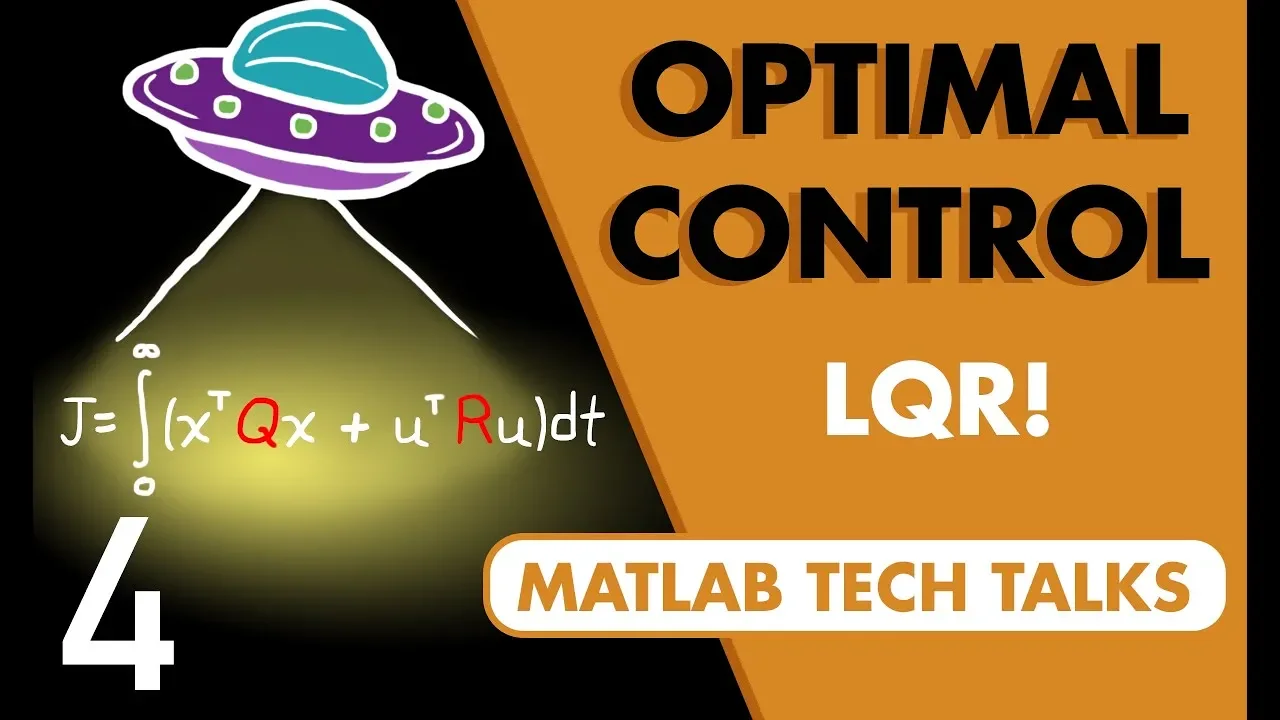
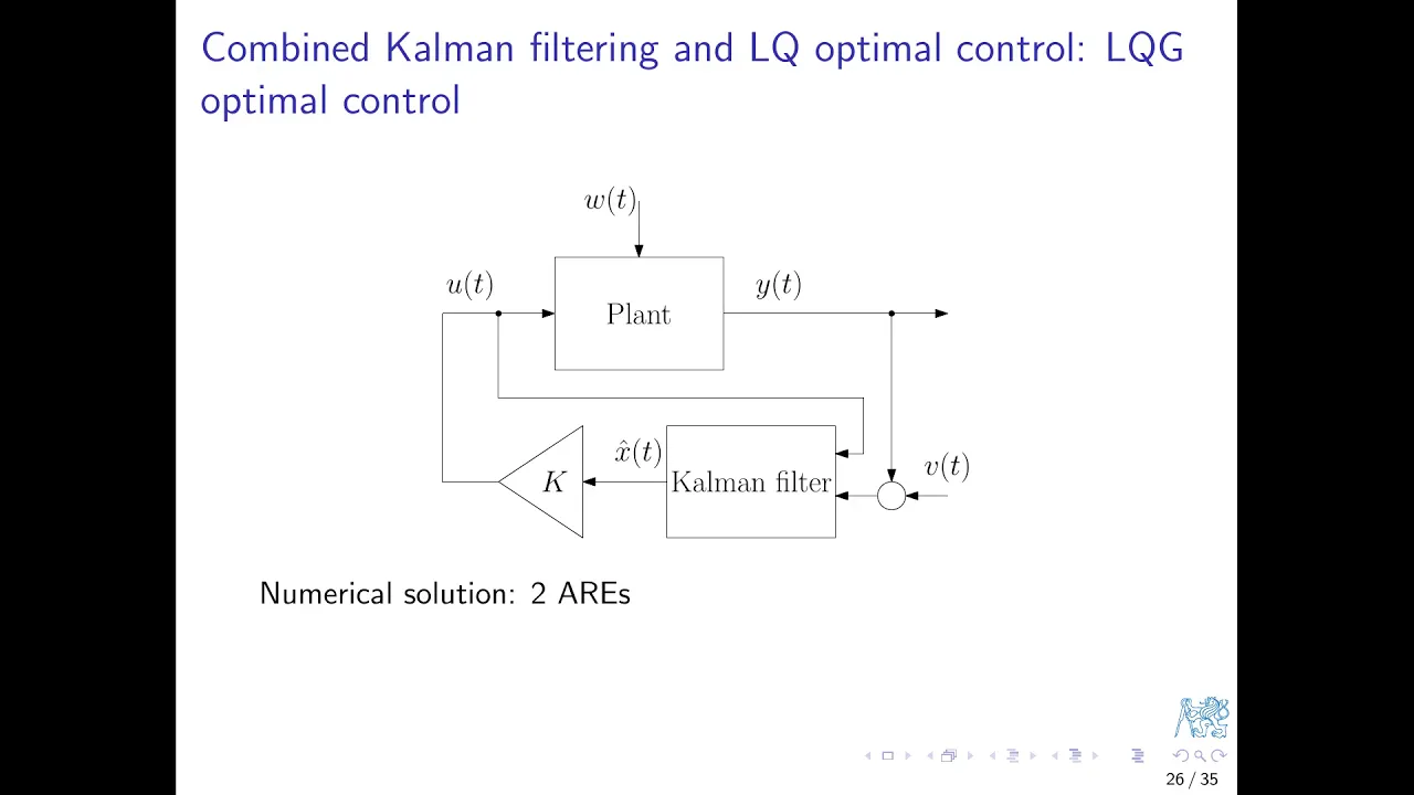
Advanced state-space control methods, such as Linear Quadratic Regulator (LQR), for more robust multi-variable stability.
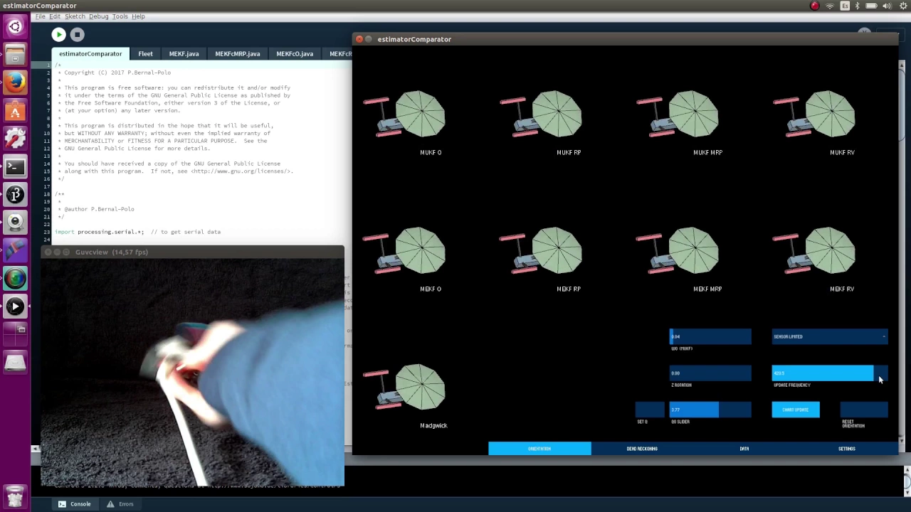
Implementing a Kalman Filter or Extended Kalman Filter (EKF) to achieve highly precise, low-noise orientation data from the IMU.
Autonomous navigation and obstacle avoidance by integrating sensors like ultrasonic transceivers or LiDAR.
Wireless communication protocols (such as Bluetooth, Wi-Fi, or ESP-NOW) for remote telemetry and real-time PID tuning adjustments.
Scaling the technology to real-world applications, such as personal mobility devices (Segways), two-wheeled cargo robots, or rocket thrust vector control.
34.3K views931likes18:14Original Release: 2020-07-31
hey what is up my name is noah and welcome to the channel this video serves as the third part to an ongoing video series where we're building our very own self-balancing robot today we're going to be programming the arduino so the robot can balance on its own if you haven't already click the link in the description to watch part one where i go into a little bit more of the control theory on how to stabilize this two degree freedom dynamic system and right below that click the link to watch part two where we've installed the electronics that we're going to be programming for today since the end of the last video i've had to move the mpu6050 so it sits flat on this mount i made because we're using the pitch angle values to stabilize the robot it couldn't be mounted on a vertical surface essentially two different angles of the robot gave the same value because the mpu6050 would turn upside down you can see that in the serial plotter here the green line represents the pitch angle values when the mpu6050 is vertical you can see it reads the same values at two different spots but when the mpu-6050 is mounted on a horizontal surface it works just fine with that out of the way let's get into the video [Music] before we get into the code we need to make a remote control that we'll use for the robot once it can stabilize on its own we'll be using this 70 millimeter by 90 millimeter proto board to mount the controller electronics and here's the wiring diagram we've drawn for the electronics that make up our remote if you'd like access to this image i've posted all cad and code on my github which is linked in the description we'll be using an arduino nano as our logic board along with an nrf24l01 to communicate with the self-balancing robot to control the robot we'll be using these two axis joysticks these are essentially two potentiometers mounted in such a way that each one controls a different axis if we supply 5 volts across the joystick the potentiometers act as voltage dividers and because the arduino nano uses a 10 bit analog to digital converter we'll be able to read values from 0 to 1023 and what is a remote without a nice clicky switch we want this to be a modular clean design so we're going to be mounting all electronic components on header pins and all wiring will be done on the back of the board we'll start by drilling holes into the protoboard to mount the joysticks we'll be attaching them with nylon pcb standoffs next we'll solder header pins onto the protoboard for all of our electronic components with that done we can move on and make some ribbon cables for the joysticks and solder them to the corresponding pins [Music] with that we can plug in all of our components [Music] and get something that looks like this we'll move on and complete the wiring on the back of the board according to the wiring diagram we made [Music] next it's time to get all of these components in a case i've designed this in fusion 360.
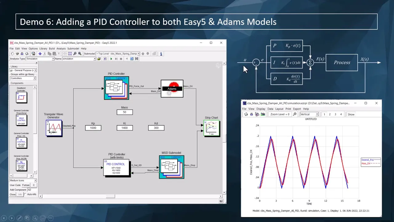
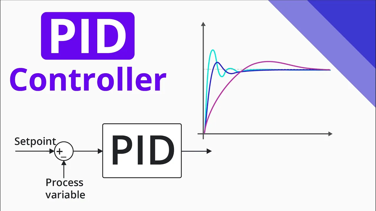
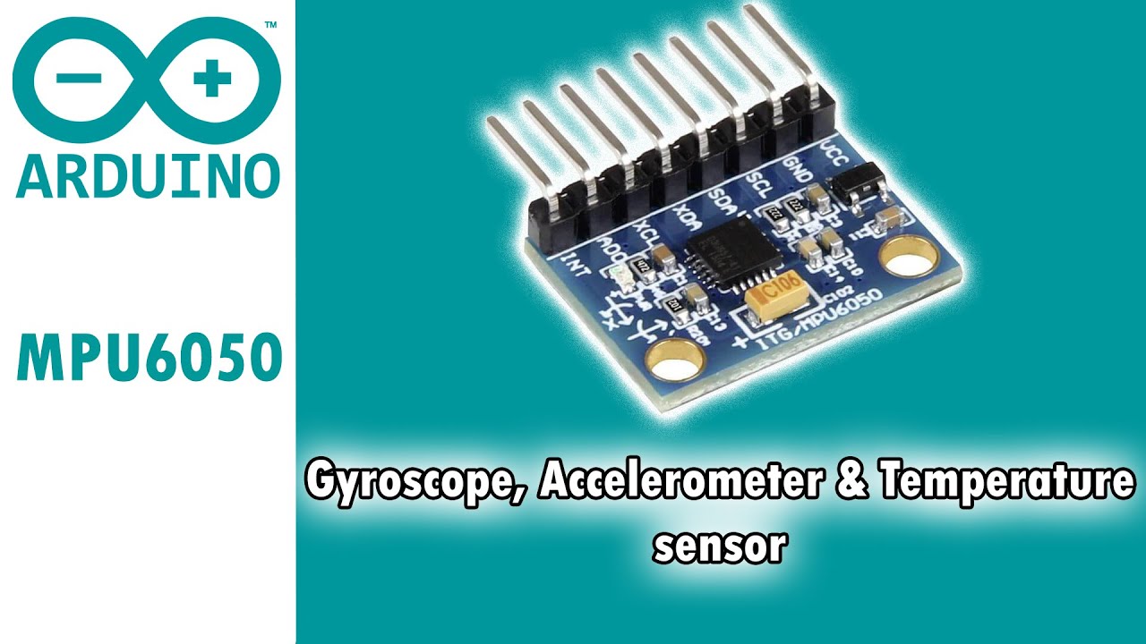
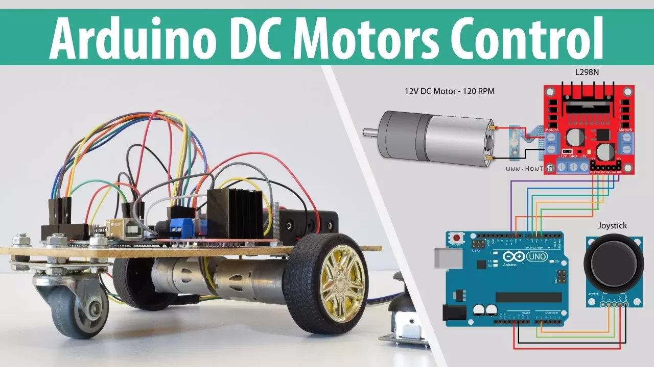
let's print it out [Music] after we fiddle around and install the pcb the battery and install our switch it's looking really good i accidentally warped this joystick with my heat gun so i'll just swap that out and with that our remote is done and i think it turned out really well you've probably noticed it doesn't have a front cover and i think i'll keep it that way for now i just think it looks really clean as it is and as a kid i always wanted to see inside the electronics of remotes and different things but we can always come back with a clear cover later there are a lot of ways we can stabilize a self-balancing robot remember at its core a self-balancing robot is an inverted pendulum in part one we talked about several ways inverted pendulums can be stabilized like with a servo at the pendulum's base or by oscillating the pivot point vertically but instead we'll be changing the force of the robot to stabilize just like you would with a broomstick balancing in the palm of your hand we want the robot to move in the same direction that it leans so the robot can catch itself if you remember from part one this is all based on torques that are equalized in this motion what we'll essentially do is set the speed of the motor based on the angle of the robot if the robot leans a little bit the wheels will move a little bit but if the robot leans a little bit more the robot will move a little bit more we'll set the speed of the motor in three ways the first is the proportional control which responds to the present or what the robot is doing right now we multiply the angle of the robot by some number and give that number right to the motors the second is the integral control this controls the speed of the robot based on what the robot has done in the past and is the accumulation of all the past error of the robot this gives the control system the property of hysteresis the third way we'll be stabilizing the robot is the derivative control this anticipates future behavior and reacts to quick changes of the robot together proportional integral and derivative becomes a pid control loop the key is to tune these gain values so the robot will respond in the right way to solidify this idea i've created this block diagram in simulink here we have an initial set point angle which in this case is a zero this value is compared to the current angle of the robot and the difference is fed into the pid controller the controller output is sent to the plant which in this case represents an inverted pendulum on a cart and includes all of the equations of motion of that dynamic system this plant was designed through a collaboration between the university of michigan and carnegie mellon university and it focuses on control and simulink i'll leave a link to this in the description and now the new angle is sent back to the beginning and the process starts all over and repeats itself the beauty of this system is that it dynamically responds to any external forces that are applied to the robot now what we could actually do is tune the pid values in simulink using this simulation but that would require us to get all of these parameters that i don't have right now so what we'll do instead is tune the pid values via trial and error and if we're having some trouble we'll come back to this later now i'm a mechanical engineer so software isn't necessarily something that i specialize in i finished the code now so i think what we'll do is just go through it to see how it all works what you're about to see is the product of a couple different iterations of the code and it was actually pretty difficult to figure out how to implement the control system we made using both our mechanical and electrical assemblies but let's go check it out conveniently the mpu6050 uses the i squared c protocol for communication to the arduino and we'll be using this i squared c devlib from jeff roberg on github for the mpu6050 i'm using four arduino libraries and i'll have links in the description for download if you want to check them out the first is the pid library from the arduino playground this computes our pid data based on the values that we provide namely the input sensor value which is the angle of the robot the set point which is determined both by the potentiometer on the robot and by a remote along with our pid gain values next is the rf24 library the nrf24l01 uses the spi connection for communication to the arduino so we only need to initialize this rf24 object with the ce and csn pins i'll come back to this stuff later we're using an l298n library just to simplify our code and we create motor instances here next is the mpu6050 and much of this is from jeff roberg's example code i could go into a lot more detail on how the mpu6050 combines both accelerometer and gyro data to read an accurate angle but that might be a little bit too extensive for the purposes of this video but to get our pitch angle values we run an interrupt service routine with an interrupt pin attached to pin 2.
and that is the mpu6050 saying its data is ready so that service routine goes to another tab which sets the imu data ready flag and further down it says that if that imu data flag is set to one then run the read angles function and that goes back to the same tab where we read the angles out of jeff roberg's example code having it structured this way means that it only ever reads the angles at this point in the loop regardless of when the interrupt pin is triggered which could be at any time in the code at the top of our main loop we read remote data and assign it to some variables these two values here adjust the setpoint of the robot based on how we turn the potentiometer once we have our imu data we get our pitch angle and convert it to degrees and that's the input for our control system here are just some thresholds for remote data because they don't center quite at zero the set point of our control system is based both on the value from the potentiometer and remote data so that means when i move the remote stick forward all i'm doing is changing the set point value and i let gravity do the rest of the work to turn the robot all i'm doing is adding or subtracting this turn v variable from the remote data to the output of the pid controller i have the robot so it'll only move if it's between plus or minus 25 degrees so if it tips over it'll just shut off and lastly we just tell the robot to go forward or backward based on the output of the pid controller and we have to structure it this way because of the nature of the h bridge on the l298 for the remote we're setting up the rf24 object here and we have this address which is the same as what we have in our code for the robot this allows both nrf24l01 modules to communicate with each other and we're just reading data from the joysticks and assigning them to these variables here to receive data from both joysticks at the same time i had to create this control values array this way i can send the remote data from both joysticks simultaneously with no delay and i can read them in the code for the self-balancing robot [Music] during initial testing the old coat wire stabilizers actually didn't do anything to keep the robot from falling over so i had to come up with this redesign we're actually upgraded to a plastic coat hanger and have these round pieces to kind of let the robot skid across the ground instead of becoming a pivot point for the robot to tip over on also i've added this toggle switch here for the motors and that replaces the switch that used to be on the board just to make it a bit more convenient to turn the robot on and off but now that the code is done and we have the rest of this mechanical assembly let's see the robot finally working [Music] you can see here how the robot dynamically responds to any force applied to the system pretty cool stuff [Music] so the robot moves around pretty well here's the kind of like an aerial shot [Applause] and here's me with the remote so i have the vertical axis going forward and backwards on the left joystick and the horizontal axis of the right joystick to turn and it can move between carpet and hardwood pretty easily [Music] one thing here is that because of the nature of the pid controller specifically the very high integral gain value i have it undergoes this stable oscillation i think this is actually because of the mechanical assembly on the motor where the gearbox has some play it's a spur gearbox so when the robot tries to switch directions the wheels lag behind a little bit and it oscillates like this [Music] [Applause] [Music] [Applause] [Music] and of course if the robot ever tips over the coat hanger is there to save itself [Music] [Applause] [Music] with that we've created mechanical electrical and control systems to build this self-balancing robot all in all i'm really happy with how it turned out i'm going to be uploading one more video just to summarize the project and highlight any challenges we had to overcome if you have any questions about the project leave them in the description and i'll try to answer as many as i can with that i think i'll sign off i'm noah thanks for watching and i'll see you around [Music] bye [Music] [Music] you
Up Next

2:07
MPU-6050 IMU Data Fusion with Complementary Filter | Arduino & Processing
@geekmomprojects
174.2K views•2013-04-02

58:25
MathWorks Virtual RoboSub Simulation Environment | Webinar 2026
@RoboNationInc
209 views•2026-03-10

11:04
How to Build a Self-Balancing Robot: Arduino Nano & MPU6050
@easytechzones
16.8K views•2022-03-09

25:22
Micromouse: The Fastest Maze-Solving Robots on Earth
@veritasium
23.5M views•2023-05-24
Related Study Plans & Knowledge Roadmaps
Structured learning paths in Robotics
robotics
Building Delta Robots: Kinematics & Pico
01Foundations of Delta Robots & Mechanical Design
02Electronics and Microcontroller Setup with Pi Pico
03Delta Robot Kinematics and Coordinate Math
+ 3 more learning modules
65h6 modules
Explore Roadmap
robotics
Building Ballbots: Dynamics, Kalman & LQR
01Embedded Electronics & Omniwheel Actuation
02Ballbot Kinematics & Rigid Body Dynamics
03IMU Sensors & Kalman Filter State Estimation
+ 2 more learning modules
42h5 modules
Explore Roadmap
robotics
Micromouse: Hardware, PID Control & Flood-Fill
01Electronics & Teensy Microcontroller Basics
02Sensors and Actuators: Motors, Encoders & IR
03Precision Movement: Implementing PID Control
+ 2 more learning modules
35h5 modules
Explore Roadmap
robotics
CDPR: Kinematics, Arduino & Winch Control
01Foundations of Arduino & Basic Electronics
02Stepper Motors and Winch Mechanics
03Kinematics of 2D Cable-Driven Robots
+ 2 more learning modules
28h5 modules
Explore Roadmap