

















![[ROS Q&A] 221 - How to setup MoveIt! for a Robot Manipulator](https://i.ytimg.com/vi/QdzmMRXAks4/hqdefault.jpg)


![ros2_control with ROS2 [1h20 Crash Course]](https://i.ytimg.com/vi/B9SbYjQSBY8/maxresdefault.jpg)


![[Gazebo in 5 minutes] 008 - How to visualize a robot URDF using RVIZ](https://i.ytimg.com/vi/N1QsVM5imsU/hqdefault.jpg)


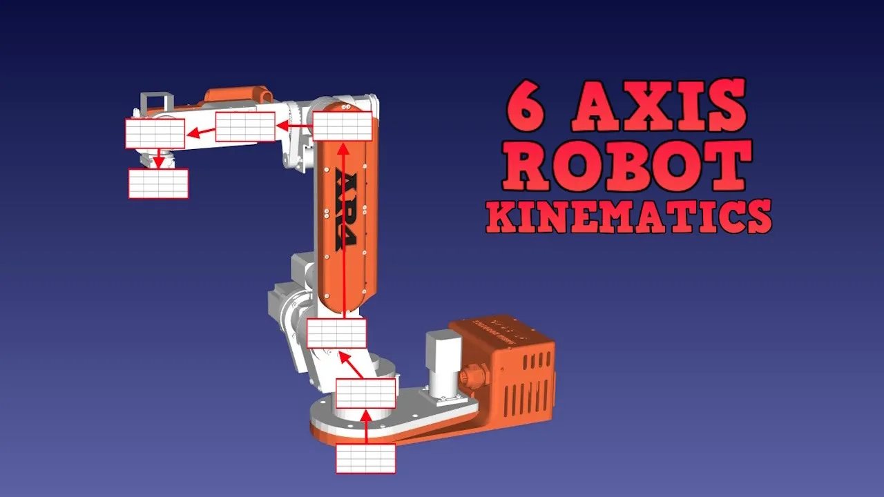


URDF (Unified Robot Description Format) is an XML-based standard in ROS that describes robot physical characteristics using links (rigid bodies) and joints (connections between links), where links define the robot's physical structure and joints specify how links relate to each other through different motion types (revolute, continuous, prismatic, fixed), with visual, collision, and inertial properties enabling accurate simulation and visualization.
Robot Modeling with URDF: A Hands-On Guide for ROS
Added:Basic ROS (Robot Operating System) concepts, including workspaces, nodes, packages, and launch files.
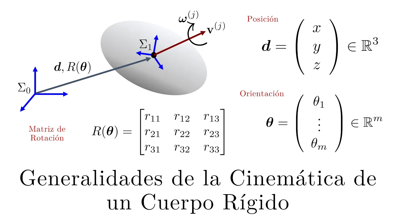
Fundamentals of rigid-body kinematics, including coordinate frames, 3D transformations, and joint types (revolute, prismatic, and fixed).
XML syntax and structure, as URDF and xacro files are written in XML formats.
Basic physics concepts of rigid bodies, specifically mass, center of mass, and moments of inertia (inertia tensors).
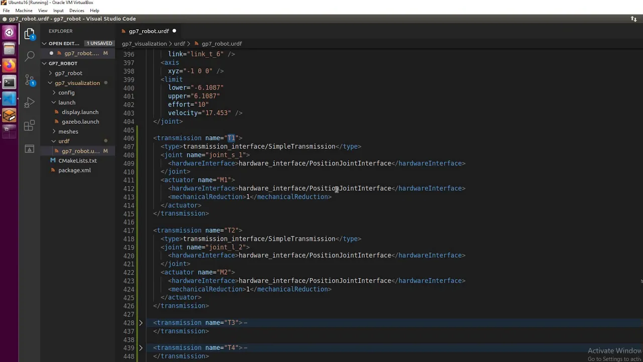
Simulating the URDF model in Gazebo by adding collision, transmission, and gazebo-specific XML tags.
Integrating the robot model with MoveIt! for motion planning, collision avoidance, and manipulator control.
Using ros_control to implement joint actuators and controllers (position, velocity, effort) on the modeled robot.
Visualizing and debugging joint states and transform trees (TF) in RViz using joint_state_publisher and robot_state_publisher.
Applying forward and inverse kinematics (IK) solvers (like KDL or TRAC-IK) to control the robot's end-effector.
124K views2.8Klikes27:34Original Release: 2021-10-25
when we're designing robotic systems it helps if we have a common language that we can use to describe our robot there might be many different software components that all need to know about the physical characteristics of the robot so for simplicity and consistency it helps if we can keep this information in one location where all of the code can reference it in ros we call this the robot description and this information is stored in a format called urdf which stands for unified robot description format we encountered uidf files briefly in the last tutorial but this time we're going to dig a bit deeper and learn how we can use them to describe our own robot now when you open up a uidf file it can be pretty scary it's really long and full of all these words and symbols and that sort of thing but if we take a moment to look more closely and break it down we'll see that it's actually made up of a whole bunch of simple structures repeated over and over again so in this video we're going to step through those structures to understand them and then we're going to look at an example uidf file break it down and see what it's doing also if you just came from the last video i know i said we were going to be doing simulations this time but as i started on that i realized that uidf was going to take up a whole video on its own so watch this one and then next time i promise we'll be learning how to do simulations in gazebo so let's get started [Music] so let's say we've got a robot and we want to describe it using urdf the first step is to break the physical structure down into separate components which we call links there's a fair bit of freedom here but if we're having trouble figuring out what our links should be there are two things to keep in mind firstly if two parts can move independently of each other then they're gonna need to be separate links secondly if it just makes sense for two parts to be separated maybe we've got a sensor or some other module that could be removed then it should probably be a separate link we get to choose where the origin for the links coordinate system is and it doesn't matter too much where we put it except for rotating links which should have their origin at the pivot point so here we might have a link for the base one for the little block which i'll call slider one for the arm and then finally one for the camera at the end of the arm then we need to understand how the links are joined together how they relate to each other these connections between links are called joints and more specifically the joints define the relationship between the origins or the coordinate frames of the links and this effectively determines the position and also the rotation of each link in space each link apart from the first one will have a corresponding joint that says what other link it was connected to its parent and how it's connected to the parent each link can only have one parent but it can have many child links each of which will have their own joints defining their position so here we would have a joint from the base to the slider one from the slider to the arm and one from the arm to the camera when we're describing a joint we also have to specify what type of motion it uses there are a bunch to choose from but there are four common types that will cover most use cases first up is revolut so this is rotational motion about a point with a fixed start and stop angle so fixed limits you can think of something like a robotic arm secondly is continuous so this is also rotational motion about a point but this is where there's no fixed limits it can spin freely forever so you might think of something like a wheel or maybe a spinning gripper at the end of an arm that can rotate continuously thirdly is prismatic so this is a linear translational motion so something like a linear actuator that moves along a rod and fourthly is fixed so this is where the child link doesn't move relative to the parent link and we use these for those kind of links where we are just making one for convenience because it makes more sense to keep things separated so there are a few other joint types out there that you can choose from but these four will cover you for almost all scenarios now this might all sound pretty confusing but we're going to dive into the uidf format and hopefully as we go you'll start to understand and then at the end we'll look at an example uadf is based on xml so everything is represented as a series of tags that are nested inside each other a proper xml file first has to start with an xml declaration and then after that it has one tag called the root tag and every other tag lives inside that for uidf that root tag is called the robot tag and we don't do too much interesting with it all it has is one attribute and that's the name so we use that to specify the name of our robot and so all of our other tags are going to go inside the robot tag and typically that's going to be link tags and joint tags so each link tag will represent one link we need to give it a name but we also have the option to specify three additional characteristics the visual collision and inertial properties now these are generally optional but in some situations one or more of them might be required especially when we do simulations so let's take a look at these first up visual this is what we see in rvs and gazebo and there are three aspects to this that we can specify firstly there's the geometry this is the overall shape we can make it a box a cylinder or a sphere with parameters we can adjust or we can specify a path to a 3d mesh then we've got the origin so this is an offset for the geometry so that it doesn't have to be centered around the link's origin and thirdly is the material this is basically just the color we can enter the color as an rgb triplet or if we'd already set up a material earlier as we'll see later we can just reference the name of the material just so you know this will only set the color in rvs not gazebo we'll talk more about that in the next tutorial and we can actually specify multiple visual tags for a link if we want and that way we can form more complex shapes next up is collision this is used for the physics collision calculations again we can set the geometry and the origin just like with the visual tag this will often be copy and pasted straight from the visual tag but sometimes we might want to use a simpler collision geometry for example we might have a complex mesh visually but we want to just use a box for collision for computational purposes and so like the visual tag we can have multiple collision tags to build up more complex objects finally we've got the inertial tag this is also used in the physics calculations but this is about how the link responds to forces the inertial properties are the mass of the link the origin so this is the center of mass or the center of gravity this is the point that the link could balance on which is a bit of a confusing concept in 3d for most simple cases this is just going to be the center the same as the visual and the collision origin and then finally inertia this is the rotational inertia matrix and it's probably the most confusing part of this section if you haven't come across it before this describes how the distribution of mass affects rotation of the link wikipedia has a good list of the inertia matrices or tensors for common shapes and we can get a pretty accurate simulation just by approximating our links as prisms ellipsoids or cylinders a rough guess will usually be fine and remember the inertia tag is for the inertia matrix which lives inside the inner shull tag which specifies all the inertial properties together now at the end of the video we're going to see all three of these in action together on the example robot and we'll also see a trick to make doing the inertia matrix calculations much easier although we primarily think of the robot in terms of links it's actually the joints that are where all the detail is at in terms of the robot structure this is because it's the joints that actually define where the links are in space this is kind of like in the last tutorial where we looked at transforms although we're interacting with the frames it's the transforms themselves that define where the frames are in space and so it's most important that we get them right each joint will need to have the following specified a name it's always good to name your joints some circumstances you don't have to but it's good to just name them all the time the type so that's what we talked about before fixed prismatic revolut continuous parent and child links so that's which links this joint defines a relationship between so this joint is effectively defining the location of the child link with respect to the parent link and finally the origin so this is the relationship between the two links before any motion is applied now that's good enough for a fixed joint but for a non-fixed joint we're going to need to specify a couple of extra characteristics there are a few that we can do but the two that we pretty much always need are the axis and the limits so the axis determines uh which axis the joint moves along or around so that could be x or y or z or some combination of them and the limits determine the physical limitations of the joint so those are the upper and lower position limits in radians or in meters the velocity limits in radians per second or meters per second and the effort limits so that'll be in newtons or in newton metres again if this all sounds a bit complicated we'll be working through an example at the end of the video and hopefully that'll make everything clear so far we've seen the robot tag the link tag and the joint tag and these are the main things that you're going to see in every uidf however the way that uidf is designed is that there are a few other tags and you can also add your own and certain nodes might be expecting certain other tags to exist depending on how you've got it set up some of the other tags that you'll pretty often see in a uidf are a material tag so this lets us name a color so that we can reuse it multiple times you can see a gazebo tag so when we're doing simulations we can specify a couple of extra parameters for how we want the simulation to work and transmission tags these define how an actuator is connected to a joint so there are these and other tags out there that you might come across every so often another thing that's worth chatting about is naming conventions as we said we need to name all of our links and it's also good to name all of our joints too it's worth where we can trying to follow some conventions as we do this uh there are certain ros naming conventions for mobile platforms and humanoid platforms and that sort of thing however it's worth even just having your own little conventions to keep things consistent for example you might have the suffix underscore link on every link that you do and then the suffix underscore joint on every joint that goes with that link so you have the arm link and the arm joint and the wrist link and the wrist joint and by doing this it just means that when you're working on the project or if someone else is looking at your urdf it's much easier to figure out what's going on and to understand how the robot works before we look at an example of a uidf file it's worth learning about a tool that ross provides to make them easier to work with and that's called xacro or maybe xacro i don't know it's short for xml macro and it's a tool that lets us take your idf files and do a lot more things with them there are a bunch of things it can do but the two that we're going to look at today are using split up files into multiple files and to avoid repeating ourselves when we write uadf files there's often a lot of things that we have to repeat over and over again and exactry gives us some tools to avoid doing that to enable the use of xacro in our files all we need to do is add this little extra bit to our robot tags that you can see up there now it's good to just put this into every robot tag in every uidf file that you do it doesn't hurt to have it there and it means that we always have the option of using xacro if we need it then basically whenever we need to use our urdf file we need to run the xacro program on it first that'll take the file or multiple files if we've split it up and it'll process through them figuring out anything it needs to do and spit out a single complete uidf into memory what we normally do is then feed that result straight into robot state publisher which then publishes the complete uidf on the robot description topic and that way any node that needs it can see it we usually use a launch file to do all of this so we would read the urdf files pass them into xacro pass it into robot state publisher which then puts it on the on the topic and so we can then write that launch file once and just reuse it in as many projects as we want being able to split our urdf up into multiple files is really useful because otherwise they become very big and unwieldy separating components out makes it easier to find things that we're looking for to change them makes it easier to share bits between different projects and to use version control software like git to quickly see what's been changed how we split up a uidf is going to depend a little bit on the individual developer and the project that they're working on for example we might want to split up the core structure of the robot into one file the materials that we're using into a file the sensors that we're using into a file and the macros that we're using into a file we'll learn more about them in a minute but you can really split it up however you like so how does it work to start off with we'll have one main file that represents the robot and as usual this robot tag has its name as well as the little exacto bit that we saw just before now inside this file we can include another file and it'll be sort of like all the tags that are in the included file are copied and pasted into the main file so to include another file all we got to do is put that include tag now for this to work the included file has to be a bit special too like the main file it will also have a robot tag usually with the xacrobit but we don't need to specify a name this time if we don't want to then we can put whatever tags that we want to include inside that robot tag sometimes we might want to give this robot a name and that way we can treat it as a robot of its own it'll sort of depend on your situation then we can include as many of these urdf exactly files as we want either nesting them or in series and we can mix and match the includes as well as normal tags we usually give the main urdf file the extension.urdf.xacro but the included ones tend to vary a bit sometimes we just use exactro sometimes they'll also be uadf.xacro some people will have their own extensions that they want to use the other thing x-acro helps us to do is avoid repeating code there's a principle in programming called dry which stands for don't repeat yourself and that means that anywhere that we can we want to avoid having the same information on the same procedure repeated multiple times there's a few reasons we want to do this the more times you've got to write it the more chances you have of doing it wrong and then when you want to go and change something you have to go and check all the spots to make sure you change it and then if you miss one you can end up with really hard to find bugs because there are two things that are doing almost the same thing but slightly different there are a whole lot of ways that xactro can help us simplify our uidf files and avoid repeating ourselves and avoid making mistakes some of the most common ones are properties so we can declare a property to be equal to some value and then reference it by name later on mathematical operators so we can perform operations and use mathematical constants within our attributes and macros which are basically like a template for a tag that can take parameters in and then we can reuse that template over and over in different places okay so that's a lot of stuff that we've covered so far what we're going to do now is dig into an example and we're going to see each of these things in action and hopefully get a bit of a better understanding for how they work okay so here's an example of a fairly simple robot and we're going to step through the urdf for it so this has got a bunch of joints and there are two that move so we've got a prismatic joint that can slide along the base and then we've got a revolute joint on this arm and you can kind of imagine that we've got a camera at the end of this arm so maybe this is for some remote filming system i don't know now what i'm going to do is i'm going to enable tf and i'm actually going to drop the alpha of the model down a little bit so that we can see the link origins inside each one and so we can see for this one we've got five links the world the base the slider the arm and the camera and then there are four joints that are between these so we've got a joint from world to base from base to slider from slider to arm and from arm to camera so let's step through these so start of our file we can see we've got our xml deck our xml declaration we've got our robot tag with the x-acto namespace and we also specify the name of our robot called robot very original now the first thing we've got here is an exactro include and we can see it's including a file called exampleinclude.xacro so let's have a look at what's in there again it's got the start tags and then we've got three materials so we're specifying white orange and blue and then we also specify some macros now we're going to get into these macros a bit later so we won't worry about them just now so go back to here so the contents of that we can imagine getting copied and pasted to here and then we have our first link and that link is called world and that's empty because it kind of just represents an anchor point for the world there's no visual thing to go with it now the next link is going to be our base link and so we need a base joint for it so the base joint goes from world to base link and you can see it's 1.5 across in x and one forward in y so if we look at this from the top we go from well 1.5 across and one forward and we can see the base link there so if we do that we can see the base link is also at zero so that's the base joint now let's look at the base link so we've got a visual tag which specifies an origin now the only thing we've got here is we've gone zed 0.05 and the point of that is that if this was centered around the base link then the uh the visual component would be sitting in the ground and so our box is has a thickness of 0.1 meters in z and so we need to raise it up by half of that in order for the box to kind of sit flush with the ground so we've got our box that's 2.5 meters long 1.5 meters wide and 0.1 meter high and you'll notice here we're specifying the material manually we still need to enter a name for it but we're specifying a color and so i've picked this green color here and then we've got the collision which is exactly the same as the visual just without a material and then finally the inertia you can see it's got the same origin i've set a mass and then we've got these inertial parameters which i've calculated myself based on the the matrices that you can find online so that's the the inertial matrix for a rectangular prism with mass 12.
next up is going to be the slider joint so this is the joint from the base link to the slider link now this joint is prismatic so that means it's linear motion now we can see here the origin is minus 1.25 in x and 0.1 in z so that's saying that when we have this at 0 from the base link we're going up 0.1 so that was the thickness of our plate and then we're going back minus 1.25 so that's the the length of our plate so that when we're at 0 this is located there then the parent link is the base link the child link is the slider link now the axis here is 1 in x so that means that when this moves it'll move along the x-axis we've got a lower limit of zero so that's where we're starting and an upper limit of two so this should move a total of two meters then for now for velocity and effort i've just put large numbers in there we're not worrying about them for the moment they just need to be there and so you can see to start off with this is sitting on that grid line and then when we move it two meters you can see it now sits on that grid line sometimes you'll find that transparency goes a bit funny with with rvs so we can adjust that joint state and that will move the joint so then slide a link what have we got here we've got same sort of thing that we did with the box where we shifted up by half of the thickness of the box now this time we've just said material name is blue we haven't specified a color and that's because we defined a material called blue back here in our included file and so we could then include this in a different robot and also use blue in that robot so we've got that we've got the collision box which is just again copied and pasted from the visual and now let's have a look at the inertial here for the inertial parameters in this one we had to specify everything so specify the origin the mass and then each of these little elements of the inertia matrix for this one we've used exactro inertial box and all we did was specify a mass for x y and z lengths so these are exactly the same as what we used here in the visual and the collision tags and then we put the origin in here and what this does is it's going to use this inertial box macro here and says okay we specified the mass xyz and then we put an origin tag in it so it'll take that origin tag it'll put it in there and then it'll take those mass and x and y and z values and do all the calculations that it needs to spit out the full inertial block that you would use for a box and so that saves us having to do all that maths ourselves so that's the slider link now the next joint is the one that goes from slider link to arm link so that one's called arm joint it's a revolute joint um now the only really new thing here we've got a couple of new things for one you notice that the axis here is minus one in the y that's because if we look at at this joint if we were to rotate uh anti-clockwise around this joint that would be positive and that would be pushing it down whereas i want a positive state value to be up so that means we're actually rotating around the minus y axis so a positive rotation around the minus y axis will lift our joint up the other thing we're doing here is i've set the upper limit to 90 degrees but it wants to be in radians and so we're using the mathematical feature of xacro to do pi on 2 and that way when we put that to max it should be straight up in the air so that's the arm joint next up is the arm link which is this orange cylinder here again we've got a few new things here so firstly we're using properties so i've declared a property called arm length which is the length of this arm and arm radius now this way instead of before we actually had the same values repeated over and over you can see vs codes even highlighted them because we're just having to repeat it in the visual tag and the collision tag and then sometimes even in the inertial tag this way what we can do is we can specify a property and that way if we need to change it we can change them all at once so for example let's make this 2 meters long and 0.04 meters radius and then if we rerun our joint state publisher you'll see it'll reset the positions to zero but we can see now our arm is longer and thinner and everything else has kind of moved to the correct location to match it one other thing we've done here that you might notice is that for the visual and collision and the inertial elements we've rotated the cylinder by pi on 2 in y and so that's because normally the cylinder is oriented in the z direction but we need it to be oriented along the x direction so we've had to rotate it by pi on 2 positive pi on 2 positive 90 degrees in y and that takes the z-oriented cylinder and rotates it so it's oriented along x so that's our arm link now our next link's going to be camera link and the joint from the arm to the camera is going to be called camera joint and so we can see that this one is a fixed link joint i mean and so yeah even though the camera isn't moving relative to the arm we could just make these boxes all be part of the arm this way we could then take this section and copy and paste it into a new project we could put it into its own exact file we can kind of do its own thing and it will get its own transform in the transform tree so it's useful to to specify its own link so yep nothing special there it's just a fixed joint at some set origin and again we're utilizing those properties there and then finally the camera link so the special thing about this one is we've actually composed this of multiple objects so we can see there are two visual tags the first one is this box part and then the second one is this cylindrical part and we've combined them together to make this kind of camera looking thing now for the collision again we could have just copied and pasted that but instead what we've done is we've only got one collision and we've made that a box that would encompass all of it so if you see here in rvs we tick collision enabled and you can see the box that covers up the whole camera if i turn off the visual it becomes a little bit clearer so you can see that might be a reason to use a slightly different collision mesh to what you're using for your visual mesh yep the other thing to note here is just that we actually specified a different material for the box and the cylinder but avis just looks at the first one and seems to use that for everything i don't know if that's deliberate or just a bug but just be aware of that in case you do want to make it different colors so yeah that's it that's our exactro urdf example for a simple robot i encourage you to go through have a good look through that try to understand the different things that are going on and then you can go ahead and use that to design your own robots hopefully you found that helpful to understand urdf and how we can use it in the robot design process next time as promised we'll be looking at the gazebo simulation software and how we can take that urdf and drop it into a simulation environment to see what happens if you're keen to see that make sure you subscribe so that you don't miss out if you did find this helpful please let us know in the comments or like the video thanks for watching and i'll see you next time [Music] [Music]
Up Next

58:11
Introduction to Robotics | Stanford CS223A Lecture 1
@stanford
744.4K views•2008-07-22

58:25
MathWorks Virtual RoboSub Simulation Environment | Webinar 2026
@RoboNationInc
209 views•2026-03-10
22:56
Simulating a Mobile Robot in Gazebo with ROS 2 Control Plugins
@ArticulatedRobotics
120.5K views•2022-03-04

25:22
Micromouse: The Fastest Maze-Solving Robots on Earth
@veritasium
23.5M views•2023-05-24
Related Study Plans & Knowledge Roadmaps
Structured learning paths in Robotics
robotics
Building Delta Robots: Kinematics & Pico
01Foundations of Delta Robots & Mechanical Design
02Electronics and Microcontroller Setup with Pi Pico
03Delta Robot Kinematics and Coordinate Math
+ 3 more learning modules
65h6 modules
Explore Roadmap
robotics
Building Ballbots: Dynamics, Kalman & LQR
01Embedded Electronics & Omniwheel Actuation
02Ballbot Kinematics & Rigid Body Dynamics
03IMU Sensors & Kalman Filter State Estimation
+ 2 more learning modules
42h5 modules
Explore Roadmap
robotics
Micromouse: Hardware, PID Control & Flood-Fill
01Electronics & Teensy Microcontroller Basics
02Sensors and Actuators: Motors, Encoders & IR
03Precision Movement: Implementing PID Control
+ 2 more learning modules
35h5 modules
Explore Roadmap
robotics
CDPR: Kinematics, Arduino & Winch Control
01Foundations of Arduino & Basic Electronics
02Stepper Motors and Winch Mechanics
03Kinematics of 2D Cable-Driven Robots
+ 2 more learning modules
28h5 modules
Explore Roadmap