






![SOLIDWORKS LECTURE #1: Basic SolidWorks Features [TAGALOG] - Extrude, Revolve, Loft, Sweep](https://i.ytimg.com/vi_webp/dk9otEGb40I/maxresdefault.webp)













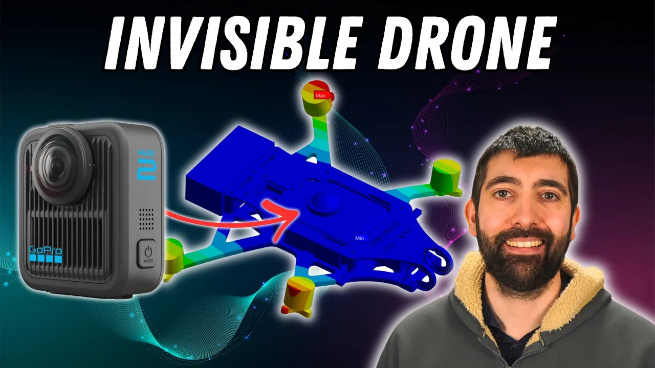
This tutorial demonstrates how to design a custom drone frame in Autodesk Fusion 360 by starting with a 2D sketch of propeller positions, extruding shapes into 3D, creating symmetrical components through mirroring and circular patterns, and adding necessary cutouts for hardware mounting while maintaining flexibility for future modifications.
How to Design a Drone Frame in Fusion 360: Tutorial
Added:Basic proficiency in Autodesk Fusion 360 interface navigation, workspace selection, and project file management.
Fundamentals of 2D parametric sketching, including the application of geometric constraints and dimensional parameters.
An understanding of basic 3D modeling features such as extrude, loft, fillet, and solid body manipulation.
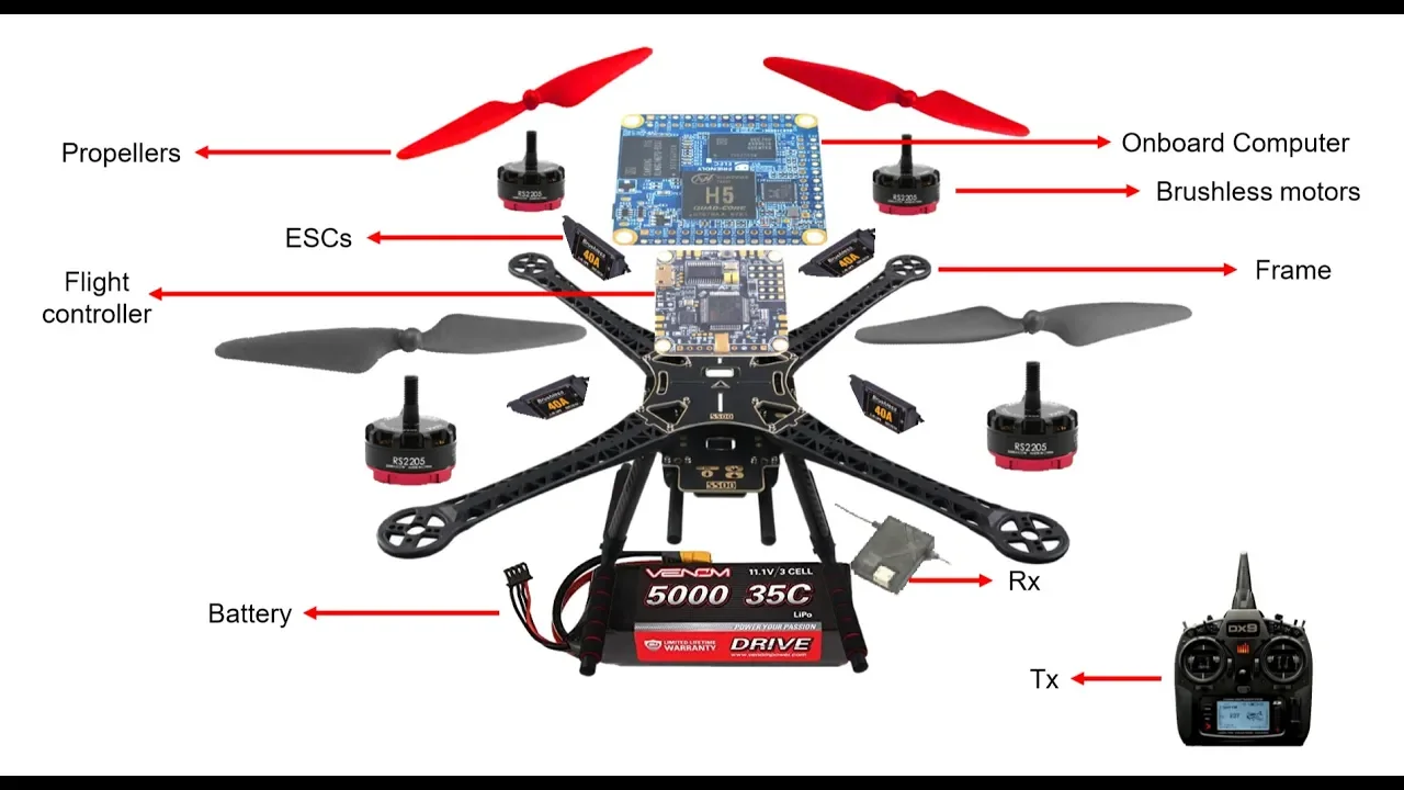
Familiarity with standard quadcopter hardware components (motors, flight controllers, ESCs, batteries) and their spatial layout requirements.
Finite Element Analysis (FEA) to evaluate stress distribution, vibrational nodes, and structural integrity under operational motor thrust and crash loads.
Generative Design and topology optimization techniques to minimize frame weight while maintaining maximum structural rigidity.
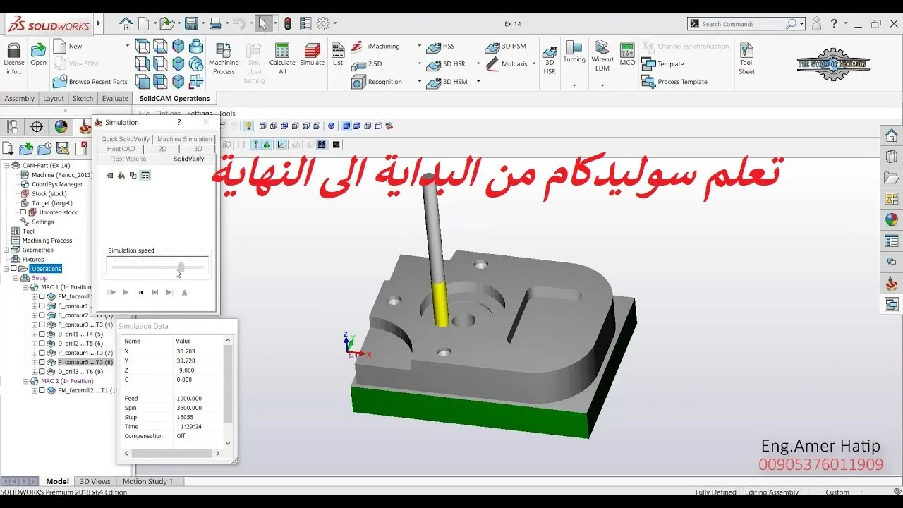
Computer-Aided Manufacturing (CAM) setup, specifically designing 2.5D toolpaths for CNC-milling carbon fiber plates or preparing models for additive manufacturing (3D printing).
Physical assembly integration, cable routing design, and center-of-gravity (CoG) calibration of the manufactured drone frame.
40.1K views809likes31:25Original Release: 2020-04-09
all right good morning I wanted to make a tutorial on designing your own frame and using Autodesk fusion 360 you can pick this up online so let's see if we can show you that real quick now on 360 so you'll go fusion 360 if you have like a college email address you can get a few more features that they'll unlock for you and to say they that you're a student but otherwise just go ahead make an account and download usually how I'll start on a project like this is I'll start out with you draw you draw out your frame on like a 2d picture of it right and then from that two-dimensional picture you will extrude these shapes into a third dimension and so you don't have to you could leave it as a 2d sketch for to sending to a company to have your frame cut out they don't need 3d solids like this to do that and that you I mean the format you're going to give them in the end is two-dimensional but it helps to have your project and 3d format like this because if you go back to designing Satan and 10ml or you need a camera mount to be 3d printed then if you have this file like this that can be easily done you've got the exact shapes yeah it just it makes it makes a life a lot easier down the road so yeah usually I'll start out by you know I'll determine if I want to build a five inch frame or three inch and so usually I will put some circles down in millimeters of the props diameter and lay those out in the configuration I want and then that gives you an idea of scale so that when you go to drawing out your bottom plate then you've got an idea of like you need to your limits on like where your frame could run into the propellers if you make it too big so it gives you an idea of scale you can bring like a known dimension like that into the into this grid and then not and then you can see it laid out if you can determine at that point if you want a stretch X frame if you want true X so well after the after I've got the propellers laid out then I'll move on to like the bottom plate here and just give usually you start with a basic shape and then you go back after you've made that and you're fine you give it more details so then you'll go back and see where you want curves and how abrupt do you want the curves to be and it'll be easier to follow once I just do it for you and then you can kind of see the workflow I just wanted to go over it all at once real quickly here and then after I've got the shape of the bottom blade it laid out then I'll move on to the arms and the arms can be they don't have to be symmetrical but it is a lot easier if you make symmetrical arms and that way you can make one side of the arm and then copy it over and then you have a full arm and then now you can copy this arm to this side and this side like vice versa so you can just mirror image that's solid and then they're in position where they need to be and in relationship to the bottom plate and so that way when you go to cut these holes through the solid then they're all lined up you know that they could cut these things these parts separately and when you go to assemble it those holes are in the right position so and then the top plate I usually it's just a like it'll be a copy of the bottom plate you know the size the outside dimension and then you can just come back and cut these shapes and you know make the shapes that you want cut out inside so let's let's just jump into it and I will I'll just start you off on the beginning alright so let's start a new project and you will do that up here there's a drop down and you can click new design and you're gonna be given a grid and so to manipulate your camera if you click and hold your right mouse button and and move around that's how you can scroll your camera view around a circle or orbit around a spot and if you click and hold the mouse wheel and move side to side or up and down it's gonna pan left and right up and down zooming in and out is your mouse wheel you just roll it forward and back for zooming so this those are those are your basic camera moves also this is this box up here where you can lock your camera into like they're you know looking from the top you can look from the right side the front or that's the back but this will just give you a straight view on what your what your draw currently drawing so let's start out usually I will start out with the sketch of the propellers and so the first thing you should do is well if you saw there I click to create a sketch and it's asking me which plane do you want to make the sketch on it doesn't matter but let's just pick X&Y and the first thing you should do is lay down some construction lines so start with the line and just click a vertical line out and or drag out a vertical line and if you see if you hover close to you know 90 degrees vertical you'll get that little symbol telling you that your snapped to a vertical position now you can click and then you're going to start going to the other direction and draw a line out like this and click this little check box to say okay so this is just gonna give you we're gonna draw the quad with this being the center of the frame right so I'm going to make it pretty simple I'm just gonna do a true x frame and so with the true you're gonna have a 45 degree angle so when you've got line selected hit tab see how we see how highlighted right now is the length of that line if you hit tab on your keyboard you go to degrees so type in 45 and now you can snap to 45 degree increments right and draw a line out longer than the frame is going to be or the arm it doesn't really matter at this point but just give yourself a 45 degree line up this direction hit OK and then we're gonna put down a propeller outline on this and we're gonna see how that looks in relationship to you know the front of your frame how how close it's going to be and a 5 inch propeller is 127 millimetres all right yes so you see how this is this is crossing over the center line which is what you don't want so just go ahead and exit out of hip escape and then they'll get rid of that and then we can click and drag out again over here 127 actually you know what's nice about fusion is you can move this stuff around so we've selected the line to start the circle and we've pulled out 127 millimetres so if you just hit Enter I believe we can click and drag this yeah so now see it's constrained everything to where you can just click and drag this out so now I can kind of manipulate how far do you want the propellers away from the centre of the frame which usually I like my frames would be pretty tight or the propellers would be close to the frame but this is that's up to you so I will leave this about like right there yeah so now this is gonna be something you're going to repeat a lot is to mirror this stuff multiple times so now and this is now you'll see why we've done these lines to select the circle and click this mirror tool and it's going to ask you what mirror line you want to use so we're going to use this one down here you see it puts another directly below it it okay now if you click and hold shift you can select multiple objects so we'll select these two and now we're going to mirror it the other direction on this line right hit OK and now you've got your propellers laid out I'm gonna turn off my camera view just in case I don't want to clip anything down here that you could miss so from here let's start building the bottom plate so I'm gonna make this like a alien style type frame where it's got a longer body in the middle and let's let's draw out half of it or you know what let's just keep it really simple so how do I want to do this there's multiple ways to do the same thing in these programs so let's so that's about 15 millimeters a 30 a 30 millimeter wide bottom plate is is pretty much I'd say the average any longer than that like 30 millimeters most lipo's are it's like pretty good width for most of the components we're using 2 to start with so let's just drag out from this halfway point 15 millimeters so just go ahead and type that in so we have 15 millimeters there and like I said this stuff can be adjusted later and I'm just gonna click a vertical line make sure that your your vertical I mean if that's what you want but it helps to keep these things square and straight and then we're just going to extend past the center point I'll show you why here I'm gonna stop that and we're gonna click from this center point all the way down and then that's gonna enclose a shape so if we click finish' sketch here now we have a shape we can extrude so you can select these again hold shift and click and then you'll select multiple and let's extrude these up so let's make this a three millimeter bottom plate alright and here is our plate you can always get your sketch back by finding it in this tree right here so the eyes crossed out you can always bring that back to look at it again or to edit that sketch but let's mirror this so if you come to this tree you can select bodies from here so if you select that body you just made and going to create there's a gear tool and now you've already selected it so it's saying you have one object selected and the mere plane that you want to mirror this on we drew it out this way so we want to mirror it on this side so let's mirror that over there and it's gonna make a new body you say ok see this is one thing it kind of oh no sorry it made two objects so they're not combined yet so we have to combine this so that the program knows that that's just one shape so if you click up here and modify there's a combine tool you can select your target body doesn't matter which one you click first and then you click the other side and say you want to join these turn off a new component that can lead to some problems down the road so we have a basic bottom plate now and from here you can shorten this up you can stretch it wider right so if you come here and select a face then you can manipulate with this tool you can manipulate the the length of that right so you can bend it be able to manipulate the link like this or let's cancel that you can go into your sketch and if you edit sketch you can manipulate the length of that like this I believe we go fit finish then your your saw is gonna follow that so I think we can yeah so now we can manipulate the sketch to change the solid or you can change the solid I mean that's up to you on how you do that so I think we'll leave this about you know about half way to the prop line and I think that that's good so the next thing to do is let's put in let's put in some holes for where the flight controller is gonna be so you usually would you would want that right in the center it doesn't have to be but let's go back to our sketch you're right click it you can edit your sketch from here again and we need four holes laid out thirty point five and millimeters apart from each other so the best way to do that from this sketch is to start from your center point and move out what would half half of thirty point five is fifteen point two five so if you type out fifteen point two five then it'll leave you a line that's close to the edge of our bottom plate so you're going to need to zoom in just like this make sure you click that handle there and it should yeah see how with the 45-degree angle we went out fifteen point two five if you go up vertically it's going to be fifteen to 0.25 hopefully this isn't too confusing but that way we can draw out a hole and 4m3 holes you can type these as three millimeter and sometimes when you get them cut from the manufacturer if you make it tight like that sometimes the hardware won't fit and you have to file or drill stuff out so usually I will give it a dimension for m3 hardware of point fifteen at the end of that just give it some wiggle room in there and usually they come out to where I can slide the hardware through the hole without any issues and yeah so let's copy that again this is the same exact procedure as the propeller so I'm gonna fast-forward you guys through this all right so now the holes are laid out and you can always double check this stuff if you go Centrepointe to Centrepointe see we're hitting that thirty point five millimeter mark on both sides so that's how you can kind of check to make sure that your dimensions are correct because it would not be cool to have a frame that you can't bolt your flight controller to alright so usually I'll just drag these into cylinders straight up so you go select everything that's a part of that circle click and hold shift this is a man we got some the lines cross in here all right and if you click over to solid we can extrude these and I'm gonna make a new body so just pull them up into space because these are gonna be holes in the end but it helps to to visualize what your stacks gonna look like so let's make a new body here right and now we can see that those holes are gonna be wider than our bottom plate let's let's add some material to this here so go into your sketch again if you right-click for the Edit sketch now we can see this is the side of our of our bottom plate right here let's add some lines back to the center let's keep it simple so if you start a line here and I'll show you why this stuff is important later and now we can return this line to the center point here I'll stop it right there all right so once you've drawn out your shape here go around and highlight all of these lines so that we can mirror this make sure to get all the way to the build plate here so that's gonna make an outline of that shape go to your mirror tool and then you can select this construction line here so that's gonna drop that there it okay and now we're gonna do this same thing again here I like all of these guys this line this and we're gonna put this on the left side make sure we grabbed everything looks good and then click mirror again and select the center mirror line right here so now we've got all that over there hit okay and so that's looking good I'll click all of these shapes extrude them and then we will make it on a shape on its own so let's extrude 3 make a new body okay and then that way that way we have control of saying we want this to be combined with that guy so that's that body that body and that story hit combine join that's right and then just click these shapes together [Music] all right this is where you can come in here and put in some curves so if you select an edge so let's select all four edges that match just or doing one one one operation at a time select these edges again hold shift and click and you can round this edge with a filler tool and then you can click and drag out a curve on that so it will curve it about like that [Music] you [Music] all right so now we've got the bottom plate we've added some material so we're now we can cut some holes into this and so one way you can do that is these cylinders that we've left behind if you select all these guys then you can click extrude and if you pass through them then now it's going to cut a hole through your plate right there now if we hit OK the cut is selected and now I've got some holes left behind and those are right where we need them to be as well so that looks good and that that is pretty much the bottom plate right there we can work with that and like I said you can always change this stuff after the fact so if we need to manipulate the sketch underneath you can change these guys too and you see since we mirrored that sketch four times it's going to do all of them at once so that's why I think it's best to leave your stuff kind of rough so that you can if you try to make a complex shape at first then I don't think fusion will let you manipulate this stuff like this and your computer might have trouble calculating it as well so that's why we that's why I tend to keep the shape basic and then come in after add the curves and then that way you can play with these play around with these and get the shape you know exactly the shape you want yeah that is the basic idea right there all right so now let's start working on laying out the arm so probably the most important part about the arm is getting your motor holes lining you know they have to be cut out correctly so that your motor wires come out on the right angle and they make motor mounts kind of weird they the pattern will be there's a 16 diameter circle and a 19 diameter circle that the motor holes are based on so before you even start you can actually come back here and adjust maybe you want your propellers this is the time to do this right now it's to figure out where you want your propellers to be positioned around your your frame here so I think I'll leave it about like let's go a little bit farther make a real wide frame so we'll position it right there and we need to edit sketch again so if you right click and edit sketch you can get into drawing on this sketch again alright so like I said the motor mounts are 16 dot 16 millimeters and they have a 19 millimeter diameter so we'll drop those in and they are they they're spread out kind of like a they're spread out 90 degrees apart from each other so the best way that I found to do this is to grab just a vertical construction line will come straight up there and hit OK and then we're going to put 2 m3 holes right here so go 3.15 I do the same thing to the motor the motor screws we have that point of 15 millimeter tolerance to it all right so now we have that shape and then let's put some lines across like this and make kind of like a like a flat egg shape here so it looks good and there's some lines in here that we don't really need anymore so the best way to do this hit is if you have line tool selected you gotta hit escape to just stop doing that and now we can can we get rid of that yeah we can get rid of these circles now because you want to save this center point right here and that center point will stay there because we have this circle so that's good and then we can come back and trim away some of these lines here so we'll trim that out if you come up here to the trim tool and that way it'll just it'll trim wherever that line intersects it's giving me a warning or losing some geometry that's fine let's exit out of Hynix cape to get off that trim tool and then let's select these lines here all right we can select that and then Mir all right so we know yes this is what I wanna do is make a circular pattern so if you you select your sketch here click circular pattern then you can define a center point so we'll click here and see now it's gonna revolve those around that center point so that's add we need four holes so see this starting to look familiar right hit okay so that is where the motor is gonna be bolted and this is where the propeller is gonna end up so on the bottom of the motor your shaft I don't know if you've noticed usually the shafts will go beyond the bottom of the mount so you need a hole here cut so that your motors will fit yes I usually will just drag out a circle about this size this dimension it's not real critical you obviously don't want too small but this will definitely accommodate for most motors here what do I want to do next don't want to finish this in xscape and now I want to like I did the bottom plate we're just gonna do a basic shape here so let's grab a your line tool and let's just put two points somewhere out here and then come back and put a point in the middle of it and then we'll grab two points here actually this will be like three we'll come back to this center of this center line right here and then this will be half of the arm and I think if we come about like that that'll be good and now it's let's mere that image so escape so we're back to this and let's select these lines that we want a mirror right mirror okay there we go we can adjust this guy a little better bring him in I'll bring this down just trying to get rid of some lines that are unnecessary right now that we don't need and we actually don't need these propeller indicators anymore as well those aren't helping us there's getting in the way so now we can select this arm shape here so I'm going to select this if I select out here that'll match up with the the bottom plate and I've got the whole arm selected and then we're gonna extrude this so I got a solid extrude and if we extrude it up its gonna run into our bottom plate so instead just do a negative dimension and we will extrude the opposite direction make sure it's a new body all right so now we've got the arm so let's go ahead and take these edges and round them up before we copy it so I'll fast forward you guys do this okay all right so we got those rounded so let's take this object and copy it onto the other corners so up here we're gonna again we're gonna go to create and miR and then we're gonna Mir with this plane I'll put it down there hit okay and then select these guys again I don't know why split them up but if you hold ctrl you can select them both and then we will mirror on this side right here all right so now you can come back here and adjust these curves and get the look you're going for so and this will this copies over at all four of those arms here so if you see on the other side we are with this one click we're affecting all the arms at once so I think that you've kind of got a good base point to start with and you know the rest of this stuff is just repeating what we just did so I wouldn't leave the arms straight like this I would match it to the top of the bottom thing right here so and that's the same you would just repeat what you did right here too to do that you'd put a sketch on top and then extrude it and combine it to that object alright so hopefully this gives you a good starting point with this program I think that from here you guys could definitely just keep repeating what we've just done and finish the rest of this frame like obviously you need some more holes for hardware and yeah let me know down below if you've got any recommendations I'm thinking I want to make some something on how to make like a GoPro mount to be 3d printed for this or or anything like that antenna mount so yeah just let me know and I will try to put something together for you all right well thank you for watching and I'll see you on the next one
Up Next
4:16
Optimizing 3D Print Orientation for Strength and Quality – A Guide
@MakersMuse
110.3K views•2015-08-19

12:54
Triumph of Orthodoxy Icon: Byzantine Art & History Explained
@BenCallan
2.1K views•2024-08-06

9:49
FastAPI vs Flask vs Django: Choosing the Right Python Web Framework
@TechWithTim
302.5K views•2024-05-26

1:42
Game of Thrones Opening Credits: A Cinematic Analysis
@gameofthrones
46.3M views•2011-04-18
Related Study Plans & Knowledge Roadmaps
Structured learning paths in General & Interdisciplinary Studies
general-studies
Elevator Engineering: History, Physics & Cities
01From Hoists to Safety Brakes: The Dawn of Vertical Lift
02Hydraulic vs. Traction: The Engineering Physics of Elevators
03Modern Speed, Safety, and Algorithms
+ 2 more learning modules
12h5 modules
Explore Roadmap
general-studies
Rubber: Material Science, History & Geopolitics
01Origins of Natural Rubber & Mesoamerican History
02The Chemistry of Natural Rubber & Vulcanization
03The Geopolitics of the Rubber Boom & Colonization
+ 2 more learning modules
12h5 modules
Explore Roadmap
general-studies
Containerization: Evolution, Logistics & Trade
01Ancient Trade & Bulk Cargo: Amphorae to Barrels
02The Industrial Revolution & Cardboard Packaging
03The Containerization Revolution: Malcom McLean
+ 2 more learning modules
12h5 modules
Explore Roadmap
general-studies
Textile Tech: Evolution, Labor & Global Impact
01Pre-Industrial Textiles: Handloom & Cottage Industry
02Mechanization: The Spinning Jenny to the Power Loom
03The Factory System & Global Labor Transformation
+ 2 more learning modules
10h5 modules
Explore Roadmap