



















This video demonstrates the complete workflow for designing a 3D printed enclosure for an Arduino Uno using Fusion 360, covering key steps including creating reference sketches from dimension drawings, using offset tools for clearance, extruding profiles for the main body, applying shell operations for wall thickness, creating mounting pins and standoffs for secure assembly, projecting geometry for accurate cutouts, and using patterns for ventilation grills, while emphasizing the importance of verifying dimensions and adding chamfers for smooth assembly.
Designing an Arduino Uno Enclosure in Fusion 360
Added:Basic user interface navigation and 2D sketching techniques in Autodesk Fusion 360, including the use of geometric constraints and dimensioning.
Fundamental 3D modeling concepts such as extruding sketches into bodies, applying fillets/chamfers, and utilizing the shell tool to hollow out shapes.
The physical layout and geometry of the Arduino Uno, specifically the placement of the USB port, power jack, header pins, and mounting holes.
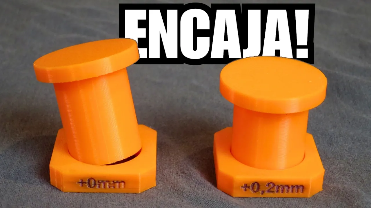
The concept of mechanical tolerances and clearance fits in 3D printing to ensure physical parts slide or snap together correctly.
Mastering parametric design in Fusion 360, using user parameters to create adaptable enclosures that can easily resize for other development boards.
Designing advanced closure and fastening mechanisms, such as snap-fit joints, sliding lids, and modeled threads for screws or brass inserts.
Integrating thermal management into electronics enclosures, including passive ventilation grilles and active cooling fan mounts.
Applying Design for Manufacturing (DFM) rules to optimize 3D prints, focusing on minimizing support structures, printing orientation, and wall thickness.
677.3K views15.6Klikes18:14Original Release: 2015-02-23
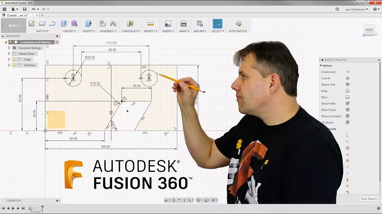
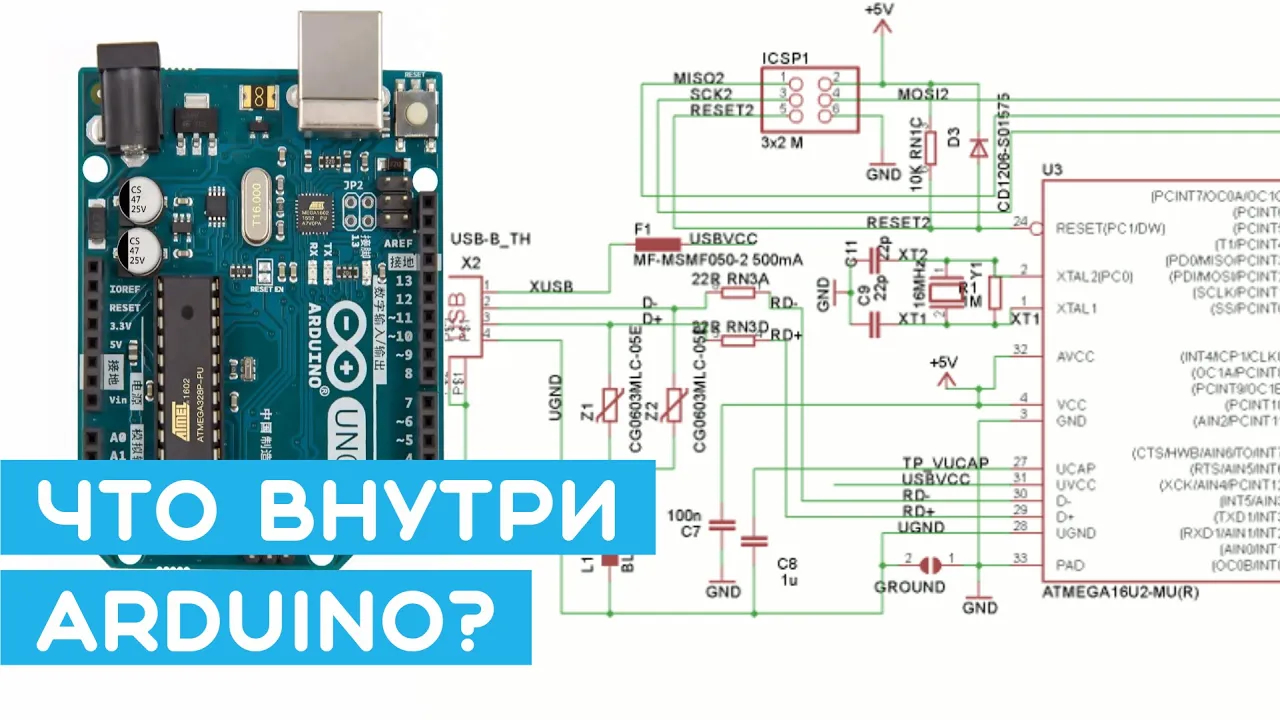
hey everyone in this Fusion 360 video I'm going to be teaching you how to design an enclosure for an uino Uno and I'm going to be recording myself along the way just so you can see how fast it is see my thought process throughout um see the mistakes that I know I'm going to make and how I fix those mistakes and hopefully learn uh a thing or two along the way so let's get started by creating a blank design and I'm going to start off by creating a sketch that really drives most of my design for this enclosure so I'll start by making a two-point rectangle so under sketch I'll choose twoo rectangle and I'm referencing some Dimension drawings that I have I can include a link to them in the description at the bottom of this video uh they're actually really handy and I think better than other dimension drawings that I could find so I'm going to start by modeling just the outside shape of my Arduino followed by some holes and I'm going to make these 2.8 mm in diameter um if you're familiar with Arduino you know that the mounting holes are actually 3.2 mm so why am I making these 2.8 well that's how big the mounting hole is and I'm actually going to be modeling some pins that are going to slide through those mounting holes and I don't want them to you know struggle to fit through there I want there to be a clean fit between them but uh some nice friction so I'm going to go for 2.8 and now using that same dimension drawing I can Dimension these relative to my Arduino so I'm going to Dimension that distance from there to here to be 2.5 and again this is all under sketch and sketch Dimension and now I'm going to Dimension the distance from that Center Point to here and that's 14 and I'm going to repeat the command and dimension there to here and that is actually 15.3 I made the mistake of thinking that that's 14 as well it's not I made an enclosure that didn't fit so make sure those are different distances and I will set the distance from here to here to be 50.7 and I'm going to go ahead and do the same thing for these so this one this distance is going to be 35.5 and it is best practice to Dimension from uh two common edges it makes it a little bit cleaner and this one is 7.6 and lastly we have a few more Dimensions here to here is going to be 66.1 and this one is actually vertical from the other one so this is 66.1 as well so now I have the holes dimensioned up uh I'm going to be building the enclosure around my uino and I want it to have a little bit of wiggle room I don't want it to have to fit perfectly within the enclosure so I'm going to use the offset tool to offset this out by just 1 mm give me a little bit of space uh and now I'll select these edges by shift selecting them right click and choose normal SL construction to make them some construction lines I'll click stop sketch and now I can choose extrude and I can extrude these profiles up so let me select these profiles and this is just really the main form of my enclosure I'm going to go with 22 mm tall and there we have it uh the next thing I'm going to do is actually shell out my body so let me go ahead and choose shell and what body do I want to Shell well it's the one I just created so I'll click that how thick if I make it 1.6 mm uh it'll actually just take two layers or two shells rather of a 3D print with A4 mm nozzle it's two shells and I want a shell outside so I'll click okay and now I want to split this in half so I'm going to create a construction plane that's a mid plane between the top and the bottom half and now that will adjust to what ever size box I have so let me go ahead and split the body with that plane and now I have a top and a bottom half and I can turn off my construction plane and that looks a little thin I might have messed up the shell so let me right click on the shell command and choose edit and what do you know I did so I'll make that 1.6 not one and outside because I don't want to kind of swallow up any of the Arduino I want to create a shell outside of it so now I have my proper shell that way now I'm going to turn the visibility of my sketch back on and I'm going to extrude these circles that I drew to create those mounting pins that are going to go through the mounting holes of my Arduino I'm going to extrude them up and I know to this surface it's going to be 11 which is half a 22 but I really want them to extend further so that they can actually snap with the top part of this enclosure and hold it all in place so I'm going to extrude 4 mm past this top surface and there we go go the last step I have is to create some standoffs so I'm going to create a sketch on this bottom face and I'm going to draw in some standoffs and standoffs really help support the uino bring it to a certain height um I'm going to make them let's see 4 mm in diameter and this is because the Arduino doesn't lay perfectly flat on the bottom of the PCB um you have a bunch of extra metal and solder on the underneath side from all the connections um so you don't really want to place it on the bottom of your enclosure cuz it's hard for it to stay flat and hard to position all your holes for all your inputs and outputs um so by using these standoffs you allow yourself to kind of raise it off the bottom floor of your enclosure and really accurately create some cutouts so now I'm going to extrude these profiles up and if you just take some measurements of an arduin you'll see that you know if you do about 4 mm that should be enough uh looks like I selected the wrong profile here so if I hold command I can deselect that one in change it to that outer profile and 4 mm should be enough and there we have it um The Next Step that I have is to create some receiving Parts on the top half of this box um I actually noticed that I forgot to add some fillets here so it doesn't look too nice and I've already shelled it so if I filled the outside here I'd lose that uniform wall thickness which would be pretty messy so I'm going to drag my cursor or my timeline behind that shell command and and now I'm going to apply a fillet here uh that way I keep that nice uniform wall thickness and you'll see I don't have to undo anything I can just add uh fill it maybe I'll make it three hit enter and I'll hit this button to run to the end of my timeline and I can hide the top or the bottom and you'll see we have that uniform wall thickness so now what I'm going to do is create a sketch on this face and what I want to do is project in the pins that I already have I want to be able to reference them so I'll choose project and I'll choose that surface along with this surface this one and this one I'll hide that body and now I have those profiles and I'm going to select them um let me hide that body select those projected lines and I'm just going to make them construction lines I don't want them to get in the way of any profiles so now they're just there for reference and now I'll make the whole for what those pins go into and I'm going to make this a 3.2 mm Hole uh if you remember my mounting pins were 2.8 so I you know I you can learn the hard way that if you make the mounting holes 2.8 as well it's not going to fit in there you're going to have a hard time uh snapping this lid together so I'm going to give it a little bit of clearance so that everything fits nicely and now I'm going to make this 5.2 that way these uh receiving portions are actually 1 mm thick uh around in radius or offsetting the diameter by 2 mm so 5.2 and I'll do the same over here 5.2 I'll click stop sketch and I'll turn on the top part of my enclosure I'll extrude these profiles and how far do I want to extrude well it's 11 to this top part and I know I have 4 mm of overlap from the pins I may want to offset this maybe just make it 10 mm so they're slightly lower than where this is splitting just to keep things clean and I still have 3 mm of intersection between them now if I come over here one quick thing I'm going to do is add a small champer um I like like these to kind of ease into the slot so I'm going to choose champer and chamfer off the top of these pins so that we can gradually push them in and if I do A4 mm champer that'll be nice um it's a factor of my layer height which is 2 mm so it should create that Cham for no problem uh the next step I have is bringing in an Arduino so I went ahead and downloaded this online I imported it to my project and now I can right click and choose insert so let me bring in this Arduino and there it is and I'll click okay I'll close the data panel and I'll quickly create some components out of the bodies that way I can actually create an assembly so I'll right click and choose create components and now you can see I move the parts all over the place so I'll right click or actually click and rename this to be enclosure bottom and this one enclosure top and I'll right click on the bottom and choose ground so it doesn't go anywhere and now I can apply a joint so which uh pieces of geometry do I want to align well let's align the bottom of this hole to how about the top of this standoff right here so let me orbit around and how about like that so now you'll see that it brings those two pieces of geometry together I have a rigid joint and let's look at it from the top everything looks great so I'll click okay and now I can add one more joint to place the lid on here so I'll choose joint and let's just align that with uh let's see here if I zoom in let's see if that worked oops let me try it one more time repeat joint and let's go with that point and that point there we go and I'll do rigid I could do slider to kind of animate it moving up and down but I'll leave this at rigid and I can do some animations later so there we have it we have the top and bottom in place we have an uina in there and it looks great a few things we need to do are make some cutouts so I'm going to create an offset plane on this surface and then I'm going to create a sketch on that offset plane and the reason I didn't sketch on this face is I didn't want to bring in this geometry necessarily I just wanted a clean sketch on that face without bringing it in so that's a little bit of a a tip right there and now what I'm going to do is project in some geometry from the uino so how about this port right here and now I can start importing in or projecting in some of these edges that I'd like so how about just the Outer Perimeter it's not registering it as a loop so I'm just going to have to click these edges myself not too bad and one more over here I'll click okay and if I hide the Arduino you'll see that we have those profiles and I'm going to make this one a construction line again so I have some cleaner profiles and I want to offset this slightly because this is the exact size of the uh the components that are sticking out of my Arduino and if they're slightly bigger smaller at a different angle I want this to still fit so I'm going to choose offset and offset by maybe just half a millimeter outside give myself a little bit of wiggle room and offset this half a millimeter as well I'll choose stop sketch and now I can extrude those two profiles so let me click on both of those and if I go in I'll make a cut and I want this to be dynamic I want it to adjust to the thickness of my Arduino so so instead of just extruding them blindly some random amount I'll say extrude them to this inner surface and now when my wall thickness changes so will that Extrusion and before I click okay I'll make sure that my top enclosure component is visible as well so it cuts through that component just like that and if I turn my Arduino visibility on now you'll see it poking through uh you might be wondering you know why are you making an enclosure for this if right now we can't actually access the pins in my Arduino so it's pretty hard to prototype with this we'd have to take the top off and that's a little bit of a pain so what I want to do is make some cutouts on this top surface so that I can access those pins so let me hide the actually I don't need to hide anything let me just project in some of that geometry from the Arduino and I don't want to project in all of this mess I just want to project in how about that corner and this corner and then this one and this one and I'll click okay hide the Arduino and now what I can do oops I guess I messed that up let me try it one more time project and give me this corner there we go now what I can do is just draw some two-point rectangles to kind of snag that geometry so I'll click here and here and here and there just like that and if you'll see right now it matches up perfectly again I might want to give myself a little bit of wiggle room so how about if I do an offset of uh.5 mm and I'll do it again over here.5 mm and I'll click stop sketch turn on the top and I will now extrude again so I'll choose extrude these two profiles and I will again do an extrude two and I want to extrude to this inner surface oops looks like I selected some profiles let me deselect those and try it one more time this profile and holding command let me click that one and this one and this one there we go so now I have that Extrusion I have access to my Arduino pins and everything looks pretty good uh I could print this out and it's a working enclosure but I want to make it look a little bit nicer so how about I add some chamers to the top and the bottom and again I'm just going to do a factor of my layer height which is 2 mm so 6 works pretty well and then if I look at it from the top I don't really need all of this closed off area doesn't look super nice and I want to add something little bit more artistic so how about I create a sketch on this top face and I'm going to draw a line here from this corner to this corner so that's from one hole to the other and I could draw another line from this corner to this corner but I don't really like the way it Blends in with these curves here so I'm actually going to use the spline tool and draw a spline from this corner to this corner and then I'll move these handles around to make it tangent so I'll click on the line and move the handle to that corner and there we have it so now I want to create this sort of Grill pattern uh and to do that I'm just going to draw a line or actually first I'll draw a construction line that goes all the way down at a 90° angle I'll left click and select it and right click and turn it into a construction line and now I'll draw one sort of arbitrary line that goes perpendicular between those and this is how I like doing it just making it arbitrary and then dimensioning it to make sure it's where I want it and if I have these 3.5 mm openings I can do a quick measure actually to make sure they are 3.5 let's see and let's try that restart the selection here to here 3.5 mm and end to end we have 52 millim there we go I can know that if I have a certain number of these openings I can calculate the space in between so I believe when I did this last time I wrote it down if I had nine openings and eight full spacers in between and I wrote down the uh the width of that spacer to be 25625 millimeters you can do the math on that I think that's right um and what I'm actually going to do is now instead of drawing these lines at that spacing at 2.65 then at 3.5 I'm just going to use a pattern so I'll just do a rectangular pattern this object and this object in this direction and now how far do we want to do it what's the extent of this pattern and really I want it to end up here but what's this exact value well it has something to do with those three numbers I mentioned so it starts with 52 and then we can subtract the distance for two of these 3.5 openings which is seven and you can see you can just start typing in some numbers here to make sense and then let's lastly subtract that 2.56 25 that we have up at the top here and now you'll see it ends perfectly and how many of these do we want we're going to have eight of them like I mentioned and I'll click okay and I'll do a quick measure to make sure that this is still 3.5 and that any one of these small ones is still 2563 but we'll add another decimal and there's 625 so I'll click stop sketch I'll choose extrude I'll select these bigger profiles that I'd like to cut out and I'll just hide the Arduino in the bottom and I'll say extrude two that way if I change the thickness it will update I'll click okay and now I've made that nice looking cut out so I can turn on the Arduino and the bottom and there we have it so that's how we can Model A Arduino Uno enclosure I think we did that in about 20 minutes um if you like this video give it a thumbs up if you have any questions feel free to leave them in the comment section below and let me know do you like these kind of videos do you like seeing uh my thought process as I go through these problems and make mistakes and fix those problems throughout and if you want to reach out to me directly you can tweet me at Taylor Stein and as always thanks for watching
Up Next

93:58
Mars Colonization Challenges: NASA, SpaceX & the New Space Race
@ryv
329K views•2025-03-09

30:32
Ultrasonic Transducers: Resonant Frequency Measurement and Horn Design
@imajeenyus42
229.9K views•2017-02-22

54:16
Polymer Environmental Degradation: Mechanisms & Stabilization
@iit
1.8K views•2012-07-10

33:39
How a Student's Question Saved a NYC Skyscraper from Collapse
@veritasium
22.8M views•2025-04-26
Related Study Plans & Knowledge Roadmaps
Structured learning paths in Engineering
engineering
Building Acoustic Levitators: Physics & Arduino
01The Physics of Sound and Standing Waves
02Piezoelectric Transducers and H-Bridge Drivers
03Arduino Programming: Generating 40 kHz Signals
+ 2 more learning modules
14h5 modules
Explore Roadmap
engineering
Building Peltier Cloud Chambers: Particle Tracks
01Cosmic Rays & Cloud Chamber Physics
02Thermoelectric Cooling (TEC) Fundamentals
03Custom Liquid-Cooling Loop Design
+ 2 more learning modules
18h5 modules
Explore Roadmap
engineering
Yagi-Uda Antennas: Modeling, Build & VNA Test
01Introduction to RF and Antenna Fundamentals
02Yagi-Uda Antenna Design Principles
03Antenna Modeling and Simulation in 4NEC2
+ 2 more learning modules
18h5 modules
Explore Roadmap
engineering
ECG Monitor Design: Op-Amps, Filters & Noise
01Electronics & Breadboard Basics
02Op-Amps and Instrumentation Amplifiers
03Bioelectricity and ECG Fundamentals
+ 2 more learning modules
18h5 modules
Explore Roadmap