

![FÍSICA - Hidrostática [CICLO FREE]](https://i.ytimg.com/vi/T_Vx_suYAXY/maxresdefault.jpg)















This video demonstrates the design of a proof-of-concept autonomous profiling float for coastal ocean data collection, featuring a variable buoyancy system that uses a piston-driven mechanism to control vertical movement. The system employs a PID controller to regulate motor speed based on pressure sensor feedback, enabling the float to sink to approximately 8 feet depth and resurface. Key design considerations include using a non-captive motor with constrained lead screws, low-friction Delrin bearings, and an acrylic pressure vessel for transparency and educational purposes. The project addresses the challenge of developing affordable coastal profiling floats that can overcome operational hazards such as density gradients, wave activity, and biofouling, with a total budget of just over $500.
Proof of Concept Autonomous Profiling Float | Ocean Engineering Capstone
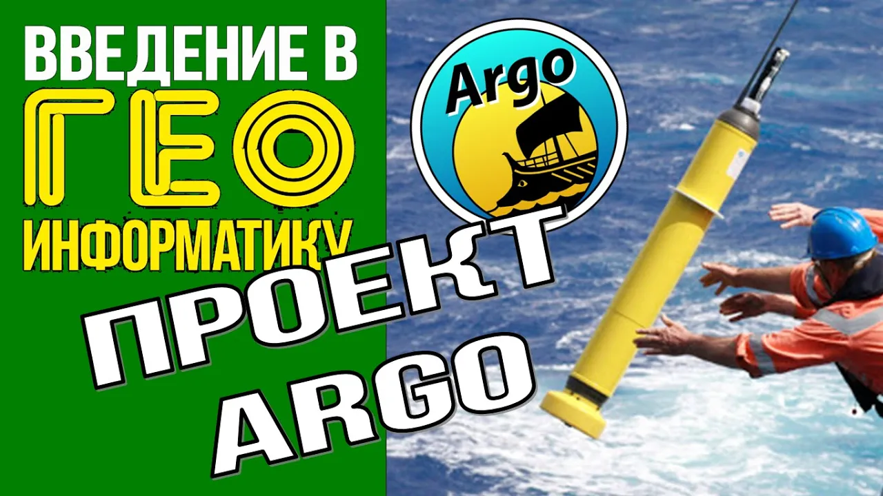
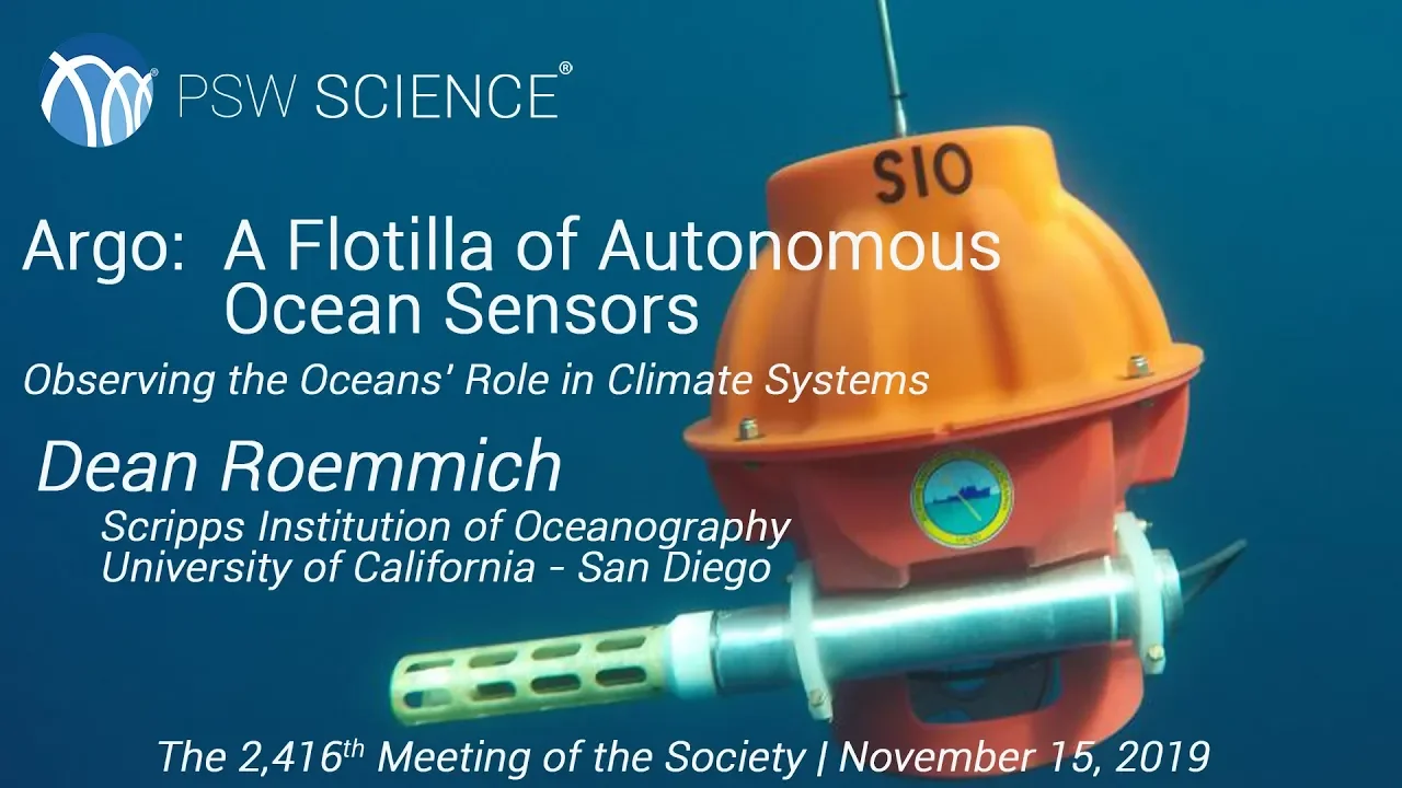
Added:good afternoon everybody my name is Corey shambley and I'm a senior in the ocean engineering program here at the University of Southern Mississippi and I'm going to talk to you all a bit about the project that I've been working on for the past year which is the design of a proof of concept autonomous profiling float so before I get into the details of my project I'm going to give a little bit of background on what exactly autonomous profiling floats are for those unfamiliar they're uh specific type of autonomous underwater vehicle that collect a variety of different ocean parameters below the surface so the movement of these profiling floats is controlled only in the vertical Direction Through the use of a buoyancy engine um and if you're unfamiliar with buoyancy systems I'll be covering that in a little more detail in a couple of slides but they only control their vertical movement while the horizontal movement is deter by waves and currents so you can see here here's the typical mission of a profiling float it's changes its volume to sink down it drifts for a specified period of time descends further to begin collecting a profile returns to the surface and then transmits that data so the most prominent profiling floats are deployed by the Argo program this is an international collaborative effort uh um they've been going since 2000 and have nearly 4,000 floats deployed as of today actually if you look at the map you'll see that this is a map from today May 9th 2024 um so the benefit of the Argo program and being a part of the Argo data stream is that they provide near realtime data and they can generate Maps like this and data daily they collect data on temperature and salinity among many other different parameters in the ocean um but this is critical for examining climate change on our oceans um and autonomous profiling floats are arguably the most powerful tool we have for examining how climate change is impacting the world's oceans so the motivation for this project is that there are currently no profiling floats that were that are rated for Waters under 1,000 MERS if you notice from the map on the last slide um all of these floats are located out past coastal areas there's a lot of international research that's been going on for years into developing Coastal autonomous profiling floats um and there's been a lot of advances but still nothing that has been brought to Market and this is the result of a number of different operational hazards that result from operating in coastal environments so you have density gradients that are created from estuaries um discharging water into the oceans um this creates you know you have saltwater freshwater mixing creating these density gradients that causes profiling floats to get basically become neutrally buoyant at depth and not be able to return to the surface you have wave activity this is maybe the most critical and the most uh the most difficult to overcome but along coastlines you've got waves that are going to be interacting with the profiling floats and there's always going to be a force that's propagating toward the shoreline that wants to push these profiling floats ashore hurricanes and severe storms this kind of leads into the wave activity when you have these severe storms you have increased wave activity in coastal zones the water is a lot warmer and warmer Waters means that you have more marine life which means biofouling becomes a a huge concern in coastal zones where the where the depth isn't as great and then of course uh you have ship traffic moving in and out of ports um if you have a float that's located at or near the surface you always run the risk of some kind of collision that could potentially destroy your float so obviously addressing all of these concerns and developing a coastal autonomous profile F in float that operates effectively is is too much to accomplish for one person so my purpose in this project simply to develop a proof of concept autonomous profiling float so now I'm going to get into a little bit of the technical details surrounding my project and beginning with the variable buoyancy system that I briefly mentioned two slides ago so variable buoyancy systems are what allow these auvs to essentially change their volume uh while keeping Mass constant and they do this through one of several mechanical processes the two most prominent um mechanical systems that you'll see to change the volume of profiling floats is a hydraulic system shown here where you have a piston or a pump transporting hydraulic fluid from inside the float to outside the float there's an external bladder on the float um so this has the effect of again keeping the mass constant and raising the volume so when you keep Mass constant and you raise the volume you uh you essentially have the effect of lowering your density and so the other system uh is a a piston style system where you have a piston that moves in and out of some kind of bearing and water is allowed to flow into the resulting C cavity that's created and it it it accomplishes the same goal of essentially changing the overall volume of the float while keeping the mass constant and you can um if you move your piston far enough you can uh change it so that you go from having a positively buoyant force to a negative negatively buoyant force and vice versa so the variable buoyancy system chosen for this project relies on a simple piston system um where a piston is driven along a bearing in the bottom end cap of the float so the Piston retracts allows water to come in this has the effect of lowering the volume increasing the density the float sinks the Piston can extend back to its original position to um restore that positively buoyant force and return to the surface so if you look at a free body diagram of the float while it's both descending and ascending you'll see that you always have your gravitational for Force pointed downward your buoyant force pointed upward all that changes is your drag force uh and depending on which direction you're moving in so as you're descending your drag force is pointing up as you're ascending drag force is pointing down so drag force is the opposite of the direction of motion um and so deriving an equation from this free body diagram uh at terminal velocity yields these equations so basically at terminal velocity you have no accelerations and you can consider it an equilibrium so I use this knowledge um to determine the stroke length of my piston by assuming a reasonable terminal velocity which was 10 cm a second so by um using the form formulas for the buoyant force for the drag force and the gravitational force at terminal velocity um under certain assumption such as the drag coefficient um I was able to actually determine how far the Piston needs to move um and what I found is that given a 3/4 in diameter piston the stroke length needs to be about 8 in to accomplish a required volume change to allow it to sink to approximately 8 ft depth so getting into the design concerns of my variable buoyancy system the primary concern um and I'm going to get into a little more detail on the specifics of my motor later but for the purposes of talking about the variable buoyancy system now I have to mention um I chose a non-captive motor for this project and the way a non-captive motor works is that a lead Le screw moves axially through the motor itself uh and so if this lead screw is not restrained in some way then it's going to rotate and that's something that's undesirable uh when you have a piston uh that that needs to be sealed against water um so I had to work around find a way to constrain the non-captive motor so to solve this issue I designed the float so that it has linear rods that are attached to the endcap and then attached up here um and I designed a guide plate with linear ball bearings um you know essentially press fit inside them to travel along and so this guide plate here is mounted to the top of the lead screw and as the uh as the motor receives signals to move um it wants to rotate but it's constrained by this guide plate so another design concern is that as you have a piston moving alongside the inside of a bearing um there's going to be some type of friction occurring so it becomes really important to have your your bearing material something with a low friction C low friction coefficient for more efficient operation um you want to to minimize that frictional force uh otherwise it could become dominant and U cause a lot of issues down the line so something like delin delin is often used in uh ocean engineering applications and it has a a very low friction coefficient that would allow um you minimal friction during movement so now I'm going to move into the mechanical design a little bit um you may have noticed from the previous models profiling floats are generally cylindrical in shape you'll sometimes see them spherical but this is for deep water applications uh when you see spherical floats because uh sphere is just the the best shape for withstanding High pressures so for the mechanical design I just chose simply an acrylic tube for the pressure vessel body uh I mentioned that that the the idea for testing is to have the float operate up to 8 ft of water which is approximately 2.5 M um you know if you start to get too deep the uh pressure becomes an issue and can actually crush the acrylic pretty easily but at 8ft depth uh it's not a concern uh it has the added benefit of being see-through uh for educational purposes so you can see it in operation it's good for troubleshooting as well top incap uh so this attaches to the top here it's got o-ring grooves right here for ceiling and the idea is to have Electronics mounted in the top end cap right here you have a bottom end cap which as I mentioned provides the bearing for the Piston but you also have mounting points for your linear motion rods and you also have a through hole that goes straight through the endcap for uh mounting a pressure sensor as well and there's a cage interface right here um this cage interface is used for both mounting the motor and housing all of the batteries that power this motor and I also designed a locking mechanism um this essentially there's a tab that comes out on the top end cap it slides in to um lock the cage interface into um you know rigidly against the top end cap um this isn't an ideal design and on future iterations I already have some ideas on how to improve this design for the locking mechanism but as of right now it's functional so moving into the motor selection I mentioned that a non-captive motor was used this is opposed to a more conventional or captive uh stepper motor um the non-c captive motor you have the lead screw that moves all the way through the motor these are especially useful when you need to optimize space um because the total length of your lead screw uh could be shorter for for moving it by moving through the motor um so you can actually save on Space by having non-c captive Motors so I looked into using both Nema 14 and Neema 17 stepper Motors um and I was looking to see that they could provide enough uh Force at a 2.5 M water depth to essentially push the Piston back to its original position restore the volume um and allow it to return to the surface so I did some theoretical calculations on what kind of force it would need to apply at a 2.5 met water depth and came to approximately 6 and a/4 pound force that needs to be applied at that depth so I tested both of the Motors on a 35 kg capacity scale so essentially what I did it's difficult to see here but I mounted the motor onto a table with two clamps and essentially I had the lead screw move downward onto the scale and see how much of a a force it could apply for the Nema 17 motor it reached Max Capacity of 35 kg on the scale um so it's able to apply a line force of at minimum 350 Newtons which comes out to about 76 lb force and the name of 14 reached about 13 Kg on the scale giving approximately 28.8 pound Force now these are both um sufficient for the depth that I want my profiling float to operate at so for the sake of um space optimization it's with an Neema 17 things would be even more tightly crammed and you'll see later that it's already tightly packed with the name of 14 but to optimize space I went with the smaller design um since it is sufficient at these tips and here's just kind of a look at various components used so what I ended up doing for the top end cap the bottom endc cap cage interface and several other components I used uh 3D printers to to print these components so here's uh three of the different 3D printers I used um that's why you have everything in different colors um but yeah uh over the last few weeks I've spent a lot of time in the lab working with the 3D printers troubleshooting 3D printers when issues arise and then here's a look at the um the assembled float in its current state so now pivoting into the electronics the way that the the the need for these Electronics is what I'm going to get into now you have a a microcontroller it reads from a pressure sensor and then it sends a signal to the motor in response to these readings so essentially it's reading pressure and it's telling the motor to either retract the Piston or extend the Piston motor driver shown here was used for efficient operation of a stepper motor a uh voltage converter um that can both step up and step down the voltage was used to um control the voltage supplied to the nema4 motor so I used three or I used four 3.7 volt lithium ion batteries and used the buck converter in this case to uh step down the voltage to the 9 volts which is the Nema 14's operating voltage and here's just a look at some of the early prototyping I did you can see here um I was originally using a different microcontroller um but because of you can see how tightly crammed everything is it was going to be next to impossible to fit a microcontroller of this size in here so it became really critical to select electronics that were as small as possible for this project moving on into the software code uh the code was written in C++ using platform IO and this is how um code was uploaded um to the microcontroller so the way the code was written is that the uh microcontroller reads measurements from the pressure sensor every second and then the motor is driven in response to these readings um there's a library called remote XY that was used um the way remote XY Works they have a website that's free to use where you can go and set up your own app to communicate with microcontrollers that have Bluetooth capabilities so here's a look at the app I created uh the purpose of doing this is to have a a toggle switch that when toggled on I can begin the float Mission so when the on switch is pressed the microcontroller starts reading from the pressure sensor and driving the motor in response and on the remote XY website it'll generate all of the code for you you can essentially copy and paste it and integrate it into your existing code to accomplish a wide variety of tests so now's a good time to mention that as of yet because of the 3D printed incaps 3D printed piston this hasn't been tested in water uh for testing in water it's going to require the use use of a PID controller that's a proportional in integral derivative controller um and this is just a kind of a feedback control system um it'll be used to control the speed that the motor operates so I took a PID controller from a previous student and adapted it for my purposes and it's been integrated but uh for water testing it needs to be experimentally tuned which means putting it out in the water and you know testing how well it works and then tuning it in response to to those uh water tests so now moving on into the skills learned and utilized um for all of the mechanical design all of the models shown earlier everything was completed in uh Autodesk Fusion which is a computerated design software I worked a lot with electronics design and programming a lot of 3D printing writing code in C++ and then learned a whole lot about the design of variable buoyancy systems and physics and fluid mechanics um to determine dimensions and the finer details of those variable buoyancy systems soft skills um working on time management uh time is short in during this project period uh and you've got got to really manage your time wisely communication we get up in front of all of our classmates and professors every week and we have kind of an interactive presentation where people can interrupt you at any time and criticize you and you got to be ready to respond to that criticism uh at the drop of a hat and then decisionmaking at the end of the day um I'm the one doing this project there are difficult decisions that have had to be made along the way and I've had to make some of those difficult decisions and then live with the consequences if it ends up not being the right decision successes and areas for improvement um so these are both kind of related to assembly and Fabrication everything went smoothly once I got started putting everything together um however the research period had carried on for far too long so in general um fabrication should have started much earlier and during that research period I spent a lot of time focusing on stuff like the pressure vessel uh things that are less critical at the kind of depths that I wanted to be testing at and not focusing on the bigger picture like uh the variable boyancy system I spent a little too much time looking a little too much into different types of variable buoyancy systems when really I should have just pulled the trigger much earlier and um started experimenting and you know fabricating stuff much earlier and another issue I had that's kind of related to the time management I I mentioned that I had uh improved my time management skills but that's really only in the last couple of weeks that I feel like I've improved my time management skills um up until then I had a a big issue with setting deadlines and then sticking to those deadlines so getting into the surprising aspects of this project the design of variable buoyancy systems is complex I I thought you know a month or two I would be able to nail down some of the finer details of a variable buoyancy system design uh but there's a lot of math a lot of calculations that go into into coming to these conclusions about you know how far does the does the motor need to drive the Piston um so it's it's a complex um complex process and I still haven't you know figured everything out it's going to require more research and another surprising aspect is that the second semester really does go too quickly uh the professors warn you at the very start um but you just kind of tell yourself oh it's going to be fine um but really it goes by very quickly so moving on to the results and conclusions um obviously this design is multifaceted interdisciplinary you see here involves mechanical design cating working with electronics lots of math um so yeah it's a it's a complex topic and further research is going to require more funding and ideally a team of experts working with me but at the at the current state my uh the idea I have is that the best approach is going to be design to design something that's lowc cost and disposable um I mentioned the operational hazards at the beginning of the presentation I don't think it's going to be feasible to overcome all of these operational hazards and going forward I'm looking into the design of something that's sold at a fraction of the cost of um profiling floats that you'll see on the market something that can be lost so in its present State the float needs encaps and piston machined and it needs to be fitted with O-rings to provide a seal and then it's going to be ready for water testing um so that's what I'm looking into right now and I'm also researching the environmental impact of components uh if it's going to be disposable you need to make sure that whatever you're putting in this float is not going to be harmful to the environment so this kind of leads into my next steps uh postgraduation I'm going to continue my education with the University of Southern Mississippi and their MBA program this is through the ocean engineering entrepreneurship pathway program I'll be starting in Fall 2024 um and so during uh during the MBA program I'll have the opportunity to continue the development of my profiling float and attempt to commercialize the design um so the work on this project is is not yet completed it's going to continue after this and my immediate next steps involve preparing the profiling float for water testing so just a quick look over my budget here uh when all was said and done the total came out to just over $500 um I did get some grant funding for this project and still have about $250 left um I don't have enough money to get everything I want so I've got to make some hard decisions for my next steps in this project but that concludes my presentation uh thanks everybody and I'll now take questions what was the most frustrating aspect of this project uh the most frustrating aspect I would say overall the mechanical design in general I mean you've got everything's interconnected and so uh it's easy to change one thing on your mechanical design and then have all these other issues that are created as a result but I would also say that while that's the most frustrating it was probably also my favorite part of the design I like working with with you know mechanical design I like working with uh CAD software as well so it's frustrating but it's also um a gratifying experience whenever you figure something out yeah twist that question too what was the most rewarding experience throughout this TR uh H well I I have this here I would just say I would just say the fact that everything more or less came together at the end um that's that's very rewarding um uh for you know a while there it looked like uh it wasn't all going to come together and I was freaking out in the last few weeks so to be holding a product right here um that's rewarding for me yes so do you have a name for no no name um but I'm open to suggestions we can it's going to live here at the lab so I figure everybody has input on what the name is known go as Dr n said I've got I've got component color cycling turned on on my on my actual that sometimes out like Su and already yeah that's a good suggestion yeah I imagine with so I'm I'm kind of just taking this one step at a time so I'm really focused on pool testing right now um and the the operational hazards are going to come at some point and so that's something to keep in mind for then um but right now I'm really focused on getting things ready for that pool testing any any thoughts of how long the battery will last uh so I did some uh I did some calculations earlier in the semester um but if I'm remembering correctly they were for the Nema 17 so this was before I switched over so off the top of my head I cannot answer that question um I would have to go back to go back to my notebook and run some quick calculations so the motivation was that most if not all of the Aros are deeper correct Waters and uh you want to design something for shallow water correct can get TR 10 surface right so in the current design is there a design element that takes that motivation into account and makes this uniquely different at this stage not really at this stage no um but the the plan is to uh start start implementing some of those at a c so that was going to be my question so if you think of that motivation how would you modify this design to kind of like so other than what said right so I'm hoping that I can learn more about um obstacle avoidance essentially if it's if it's colliding with some kind of object it's able to um realize that it's colliding with some object and take some sort of corrective action um so I think um anything yeah it's a good point yeah so it needs to have thinking of the scenario that you don't nothing hits it right but but for some reason you know there's such a high density gradient that it cannot change the points enough sure I correctly your plan was just to build something which is cheap enough if it gets lost because get yes but the idea the idea is to work in as many um Solutions as I can for these operational hazards uh but not to you know spend too much time focusing on them uh the idea is to you know um most of your profiling floats are like 15,000 to $150,000 so my thinking is if you can offer something small like this that is at a fraction of the cost you know a third or even cheaper um then it might be feasible for people uh but you know they I would say it doesn't need to have we don't need to lose 100% of them um or people you know probably will not keep buying them um so there do need to be some sort of solutions implemented um but that's that's part of future research at this point is the point recovering them is not so right if you can have business model cheap enough to recover not worth your time money spend you can say yeah that's something to consider you have to trans data yeah so I know idium satellite is not not a cheap thing to implement so maybe something like Laura where when it's at the surface it can uh find some uh some way to transmit the data a much cheaper alternative to aridium yeah think very good anybody else all right than again he
Up Next

Submarine Build 152: Variable Tank & Overpressure Valve Machining
@guernseysubmarine
271 views•2024-09-01

Ultrasonic Transducers: Resonant Frequency Measurement and Horn Design
@imajeenyus42
229.9K views•2017-02-22

Polymer Environmental Degradation: Mechanisms & Stabilization
@iit
1.8K views•2012-07-10

How a Student's Question Saved a NYC Skyscraper from Collapse
@veritasium
22.8M views•2025-04-26
Related Study Plans & Knowledge Roadmaps
Structured learning paths in Engineering