The Scotch Yoke Mechanism is a mechanical device that converts rotational motion into linear motion (and vice versa) through a sliding yolk with a slot that engages a pin on a rotating crank; it offers advantages including higher torque output with smaller cylinders, fewer moving parts for smoother operation, and improved engine efficiency due to more time spent at top dead center, but suffers from rapid slot wear due to sliding friction and reduced blow-down time in two-stroke engines.
Scotch Yoke Mechanism: 3D Motion Analysis
Added:Deep Dive
Basic kinematics of machines, including definitions of links, kinematic pairs, and degrees of freedom.

KINEMATICS OF MACHINE || LINKS || MECHANISMS || INVERSIONS || BY GAGAN BANSAL
23.2K
A machine is an assembly of resistant bodies whose relative motions are constrained to convert energy into useful work. A link is a resistant body or assembly with motion relative to other parts, classified as rigid, flexible, or fluid based on deformation characteristics. Kinematic pairs are joints between links with constrained relative motion, categorized as sliding, turning, rolling, screw, or spherical pairs, and further classified as lower pairs (surface contact) or higher pairs (line/point contact). A kinematic chain combines kinematic pairs with completely constrained motion, and when one link is fixed, it becomes a mechanism. The degree of freedom (DOF) of a mechanism is calculated using Gruebler's equation: DOF = 3n - 1 - 2J - H, where n is the number of links, J is the number of lower pairs, and H is the number of higher pairs. Grashof's law (s + l ≤ p + q) determines the type of motion in four-bar mechanisms based on link lengths.
Click to watch →

COURSEFAC - Basics of Kinematics of Machinery
19.4K
Kinematics of machinery studies the velocity and acceleration analysis of mechanical systems without considering forces. A link is a machine part with relative motion to another part, classified as unary (1 node), binary (2 nodes), or ternary (3 nodes). A kinematic pair is a system of two links with relative motion, classified by motion type (sliding, turning, rolling, screw, spherical) and contact type (higher pair with point/line contact, lower pair with surface contact). A kinematic chain forms when links connect end-to-end, with joints being junctions of multiple links. The degree of freedom (DOF) of a mechanism is calculated using Gruebler's criterion: DOF = 3(L - 1) - 2J - H, where L is the number of links, J is the number of binary joints, and H is the number of higher pairs. For a useful machine, the Gruebler's condition requires DOF = 1 and H = 0, leading to the relationship 3L - 2J = 4.
Click to watch →

TOM Revision diploma Mechanical 4th Sem | Theory of Machine IMP | Vineet Sir | Vineet Tutorials
49.5K
This comprehensive section covers the foundational concepts of kinematics in mechanical engineering. A kinematic link is two bodies connected with relative motion. A kinematic pair is when two links connect with relative motion. A kinematic chain consists of multiple kinematic pairs connected together. When one link in a kinematic chain is fixed, it becomes a mechanism. Inversion of a mechanism occurs when different links are fixed one by one, producing different mechanisms from the same kinematic chain. The three types of constrained motion are: completely constrained motion (motion in one direction), incompletely constrained motion (motion in multiple directions), and successfully constrained motion (motion completed by another link). Lower pairs involve surface contact, while higher pairs involve point contact including rolling, screw, and spherical pairs. Open pairs are in contact only by force, while closed pairs are in mechanical contact. A machine utilizes energy and converts it to useful work, while a structure transmits forces but not motion.
Click to watch →
Unit 1 - Theory of Machine | TOM | AKTU Unique Series | AKTU EXAM | mechanical Engineer | Quick
48.9K
Kinematics studies relative motion of machine parts without considering forces. A kinematic link is a rigid machine part producing relative motion, classified by motion transmission (rigid, flexible, fluid) and number of ends (binary, ternary, quaternary). A kinematic pair connects two links with completely constrained relative motion. Classification by contact: lower pairs (surface contact like piston-cylinder) and higher pairs (point/line contact like cam-follower). Classification by motion type: sliding, turning, rolling, screw, and spherical pairs. Classification by constraint: self-closed (geometry constrains motion) and force-closed (external forces maintain contact).
Click to watch →

Kinematic Pairs and their Classification | MOM | Mechanics of Machinery | KTU | S5 Mech |
24.9K
A rigid body possesses six degrees of freedom: three translational (x, y, z axes) and three rotational (about each axis). When links form kinematic pairs, constraints reduce these freedoms. The number of restraints ranges from 1 to 5 (0 implies no connection, 6 implies rigid body behavior). Class n pairs have n restraints and (6-n) degrees of freedom: Class 1 (sphere-plane, 5 DOF), Class 2 (sphere-cylinder, 4 DOF), Class 3 (spherical pair, 3 DOF), Class 4 (shaft-circular hole, 2 DOF), Class 5 (rectangular bar-slot, 1 DOF). Critical understanding: Screw pairs have only 1 DOF despite appearing to have two motions (rotation + translation), because these motions are mechanically interconnected through the thread pitch.
Click to watch →
Deep Dive
The distinction between linear (translational) and rotational motion, and how mechanical systems convert one to the other.

Les systèmes de transformation du mouvement
90.2K
Mechanical motion transformation systems convert rotational motion to linear motion and vice versa. Key systems include: (1) Screw and nut system - converts rotation to translation through helical threads; (2) Gear and rack system - uses interlocking teeth to transform rotational motion of the gear into linear motion of the rack; (3) Crankshaft, connecting rod, and slider mechanism - transforms rotational motion of the crankshaft into linear piston motion through a linkage; (4) Cam and follower system - uses a rotating cam with irregular profile to produce oscillating or reciprocating linear motion in the follower. These systems are classified as reversible or non-reversible based on whether motion can be transmitted in both directions.
Click to watch →

Lecture 8 Difference between Mechanical Translational System and Mechanical Rotational System
170
Mechanical translational systems involve linear motion where force (F) is the input and linear displacement (x) is the output, with mass (m) as the inertia element and opposing forces including viscous damping force (F_b) and spring force (F_k); whereas mechanical rotational systems involve rotational motion where torque (T) is the input and angular displacement (θ) is the output, with moment of inertia (J) as the inertia element and opposing torques including viscous damping torque (T_b) and spring torque (T_k).
Click to watch →

2026 자동제어 3
294
Translational and rotational motion systems are fundamentally different in how they are modeled and analyzed. In translational motion, the moving mass is a single unit with uniform position, requiring only one position variable. In rotational motion, different parts can move at different positions, requiring separate variables for each component. Both types of systems are typically described by second-order differential equations, with the order depending on system complexity. Laplace transform is a key mathematical technique for solving these equations by converting them from the time domain to the s-domain, making complex mechanical systems easier to analyze.
Click to watch →

Mathematical Modelling of Mechanical Systems - Mathematical Modelling of Physical Systems
94.7K
Mechanical systems are classified into two types based on their motion characteristics. Translational mechanical systems involve translatory motion, which is motion along a straight line also known as linear motion. Rotational mechanical systems involve rotational motion, which is motion of an object along its own axis.
Click to watch →

PBL 2 HỆ THỐNG ĐIỀU KHIỂN VÀ TRUYỀN ĐỘNG ĐIỆN (BUỔI 1)
4.4K
Mechanical systems typically involve two fundamental types of motion: linear (translational) motion and rotational motion. Linear motion includes applications like conveyor belts, elevators, and lifting mechanisms where loads move in straight lines. Rotational motion includes applications like pumps, fans, and machine tools where components rotate around an axis. Many systems convert between these motion types using mechanisms like lead screws, rack and pinion systems, or gear trains.
Click to watch →
Deep Dive
Fundamental concepts of Simple Harmonic Motion (SHM), specifically mathematical representations of sine and cosine displacement waves.

SIMPLE HARMONIC MOTION (ONE SHOT)
5.2K
This section explains the mathematical foundation of SHM using sinusoidal functions. Sinusoidal functions (sinθ and cosθ) are essential for describing SHM, with key properties: input angle θ can range from -∞ to +∞, output values always range from -1 to +1, sinθ graph starts from 0 and follows a wave pattern, cosθ graph starts from +1 and follows a similar wave pattern, sinθ at angle θ equals cosθ at angle (θ - 90°), and cosθ at angle θ equals sinθ at angle (θ + 90°). The displacement equation in SHM is x = a sin(ωt + φ), where x is displacement, a is amplitude, ω is angular frequency, t is time, and φ is initial phase. This equation describes how displacement varies with time and is dimensionally correct because a has units of length and sin(ωt + φ) is dimensionless. The phase constant φ determines the initial position when t = 0.
Click to watch →

Phasor Diagram in Simple Harmonic Motion SHM Questions Theory and PYQs for JEE Mains / NEET Physics
44.6K
Simple Harmonic Motion (SHM) is a periodic motion where a particle oscillates about a mean position. SHM can be understood by relating it to circular motion: a particle on a reference circle with radius equal to the amplitude A moves in circular motion, and its shadow on a plane surface performs SHM. The displacement equation is x = A sin(ωt + φ), where ω is angular frequency and φ is the initial phase. The total angle at any time is θ = φ + ωt. The choice between sine and cosine depends on the initial position at t = 0.
Click to watch →

Oscillations Lecture -4| SHM | Graphical representation of SHM |
1.5K
Simple Harmonic Motion (SHM) is described by the displacement equation x = A cos(ωt + φ), where A is amplitude, ω is angular frequency, t is time, and φ is phase constant. The choice between sine and cosine functions depends on initial conditions: starting from mean position uses sine (x = A sin(ωt)), while starting from extreme position uses cosine (x = A cos(ωt)). Velocity is the first derivative of displacement: v = -Aω sin(ωt) for cosine displacement. Acceleration is the second derivative: a = -Aω² cos(ωt). The negative sign in acceleration indicates it always opposes displacement, a fundamental characteristic of SHM.
Click to watch →

Chap 1 : LO (e) Equation of displacement for SHM and Sketch displacement against time graph [DP024]
869
Simple harmonic motion (SHM) is a periodic oscillatory motion where an object moves back and forth about an equilibrium position. Key concepts include: (1) Amplitude - the maximum displacement from equilibrium; (2) The displacement-time graph produces a sinusoidal wave pattern; (3) The displacement equation is x = a sin(ωt), where a is amplitude, ω is angular frequency, and t is time; (4) The defining characteristic is acceleration equals negative omega squared times displacement (a = -ω²x); (5) Angular frequency determines oscillation rate; (6) The general equation x = a sin(ωt + φ) includes an initial phase angle φ that determines starting position; (7) When φ = π/2, the equation simplifies to x = a cos(ωt), representing motion starting from maximum displacement rather than equilibrium.
Click to watch →

Oscillations | SHM Class 11 Physics | Part 1 | NEET Physics | NEET 2024/25
20.9K
Simple Harmonic Motion (SHM) is mathematically expressed using sine and cosine functions. The displacement of a particle in SHM is given by: y = a sin(ωt) or y = a cos(ωt), where 'a' is the amplitude, 'ω' is the angular velocity, and 't' is time. The choice between sine and cosine depends on the initial conditions of the motion.
Click to watch →
Deep Dive
Introduction to the slider-crank mechanism to serve as a baseline comparison for reciprocating motion.
Unit 1 - Theory of Machine | TOM | AKTU Unique Series | AKTU EXAM | mechanical Engineer | Quick
48.9K
The slider-crank mechanism is a modified four-bar mechanism with one sliding pair and three turning pairs, consisting of slider, connecting rod, crank, and fixed frame. It converts rotary to reciprocating motion and vice versa. The four inversions are: (1) First inversion - crank fixed, slider reciprocates (reciprocating engine); (2) Second inversion - connecting rod fixed, crank rotates and slider oscillates (quick return mechanism); (3) Third inversion - slider fixed, crank rotates and connecting rod oscillates (crank and slotted lever mechanism); (4) Fourth inversion - frame fixed, crank rotates and slider reciprocates (hand pump).
Click to watch →

Theory of Machine | Crank and Slotted Lever QRMM | Lec 13 | GATE 2021 ME Exam | By Vishva Jeet Sir
32.7K
The slider crank mechanism is a fundamental mechanical system that converts rotational motion into linear reciprocating motion. It consists of a crank (rotating part), a connecting rod, and a slider (linear moving part). This mechanism is widely used in engines, pumps, and various machines where reciprocating motion is required. The instructor introduces this topic as a key concept in machine design and kinematics, explaining how the crank rotates about a fixed point while the connecting rod connects the crank to the slider, which moves in a straight line along a guide.
Click to watch →

Link Mechanism for beginners: Lesson 2- Slider-Crank Mechanism
16.8K
The slider-crank mechanism is a fundamental mechanical system that converts rotational motion into linear reciprocating motion, consisting of a crankshaft, connecting rod, and slider; to draw this mechanism, one must establish the crankshaft point, measure the connecting rod length, mark the slider's position at multiple crank angles, and trace the locus of the slider's motion to understand how the mechanism functions throughout a complete revolution.
Click to watch →

Theory of Machine | DAY-1 | G2 Batch | Bteup Exam 2023 | Polytechnic | Mechanical Engg
24.6K
A mechanism is a combination of links that permits relative motion between them, with one link fixed and motion in one link causing definite motion in others. A slider-crank mechanism consists of a slider, connecting rod, and crank, converting rotary motion to reciprocating motion or vice versa. Mechanisms are classified as Simple (4 links) or Compound (more than 4 links).
Click to watch →

Slider-Crank Mechanism (Concise & Quick!)
20K
The slider crank mechanism is derived from a four-bar linkage through two key modifications: replacing one side link with a slider moving along a fixed ground path, and assuming infinite length for the replaced link to achieve rectilinear motion. This mechanism converts rotational motion to reciprocating motion or vice versa. Applications depend on the driver link: when the crank drives, it converts full rotation to reciprocating motion (used in air compressors); when the slider drives, it converts linear motion to rotation (used in diesel engines). Dead center positions occur when the crank and connecting rod align, requiring flywheels to maintain rotation. A related modification is the eccentric mechanism, where an off-center disc replaces the crank, providing equivalent motion with different geometric constraints.
Click to watch →
Prerequisite Knowledge
- Concept 01Basic kinematics of machines, including definitions of links, kinematic pairs, and degrees of freedom.
- Concept 02The distinction between linear (translational) and rotational motion, and how mechanical systems convert one to the other.
- Concept 03Fundamental concepts of Simple Harmonic Motion (SHM), specifically mathematical representations of sine and cosine displacement waves.
- Concept 04Introduction to the slider-crank mechanism to serve as a baseline comparison for reciprocating motion.
Subsequent Learning
- Step 01A comparative kinematic and dynamic analysis between the Scotch Yoke and the Slider-Crank mechanism, focusing on acceleration profiles and harmonic characteristics.
- Step 02Real-world engineering applications of the Scotch Yoke, such as in control valve actuators, high-pressure gas compressors, and marine steam engines.
- Step 03Tribological analysis of the mechanism, focusing on sliding friction, wear patterns in the slot, and lubrication methods to mitigate mechanical wear.
- Step 04Multi-body dynamics simulation (MBD) using CAD/CAE tools to analyze joint forces, inertia, and vibration characteristics under high-speed operation.
The Slider-Crank Dominance: Tribological and Efficiency Limitations of the Scotch Yoke
While the Scotch Yoke mechanism is praised for its compact size and ability to generate perfect simple harmonic motion, mechanical engineers often favor the classic slider-crank mechanism for practical, high-load applications. The primary criticism of the Scotch Yoke lies in its tribological performance. It relies on sliding contact between the pin and the yoke slot, which creates high contact pressures, rapid wear, and significant frictional losses. This necessitates continuous, high-performance lubrication and leads to frequent maintenance issues. Conversely, the slider-crank mechanism replaces this sliding joint with rotational bearings, which exhibit significantly lower friction, better heat dissipation, and superior longevity under heavy loads. Furthermore, while the Scotch Yoke produces a pure sine wave motion, the asymmetrical acceleration curve of a slider-crank can be advantageous in internal combustion engines by allowing more time for combustion near top dead center. Thus, from a reliability and efficiency standpoint, the slider-crank remains the industry standard, positioning the Scotch Yoke as a niche solution rather than a universal standard.
Deep Dive
A comparative kinematic and dynamic analysis between the Scotch Yoke and the Slider-Crank mechanism, focusing on acceleration profiles and harmonic characteristics.

Theory of Machines Lecture 19: Kinematic analysis of slider crank, calculation of different forces.
21.1K
This lecture covers the kinematic analysis of a slider-crank mechanism, deriving key formulas for piston displacement (X = R[1 - cosθ] + n - √(n² - sin²θ)), velocity (V = Rω[sinθ + (sin2θ)/(2n)]), and acceleration (a = Rω²[cosθ + (cos2θ)/n]), along with dynamic analysis including connecting rod angular velocity (ω_CR = ωcosθ/n), angular acceleration (α_CR = -ω²sinθ/n), piston effort, force in connecting rod (F_C = F/cosβ), normal thrust (F_N = F tanβ), radial thrust to crankshaft bearings (F_R = F_C cos(θ+β)), crank pin effort (F_P = F_C sin(θ+β)), and turning moment on crankshaft (T = F_P × R), explaining how variable acceleration causes jerks requiring flywheels for smooth operation.
Click to watch →

🔴 Scotch yoke mechanism animation || With Explanation
195.6K
The Scotch yoke mechanism is an inversion of the double slider crank mechanism consisting of four links—a fixed link, a rotating crank, a reciprocating slider, and a slotted link—that converts rotary motion into perfect harmonic reciprocating motion, making it useful for applications requiring smooth linear oscillation such as plotting sine/cosine curves.
Click to watch →
Theory of Machine | DAY-1 | G2 Batch | Bteup Exam 2023 | Polytechnic | Mechanical Engg
24.6K
The Scotch yoke mechanism is an inversion of the double slider-crank chain where one slider is fixed. The crank rotates, causing the yoke to move reciprocally. It converts rotary motion to reciprocating motion. The motion is simple and produces a straight-line path.
Click to watch →

Velocity and Acceleration diagram|Slider Crank Chain|velocity and acceleration analysis of mechanism
161.9K
This section covers the complete acceleration analysis process for a slider-crank mechanism. Radial (centripetal) acceleration components are calculated using a_r = v²/r: for input link BO, a_r = 147.89 m/s²; for link AB, a_r = 19.26 m/s². An acceleration diagram is constructed by plotting radial components from respective centers of rotation. Since angular acceleration is zero, only radial components are initially plotted. The intersection of these vectors reveals the total acceleration vectors. The tangential acceleration of link AB is measured as 100 m/s², from which angular acceleration α_AB = a_t/r = 166.67 rad/s² is calculated. The slider acceleration is found to be 102 m/s².
Click to watch →

Inversion of Mechanism - Fundamental and Types of Mechanisms - Theory of Machine
296.3K
The Scotch yoke mechanism is an example of a double slider crank chain containing two sliding pairs and two turning pairs. It consists of a fixed cylinder (link 1), a rotating crank (link 2), a first slider (link 3), and a second slider (link 4). When the crank rotates, the first slider slides within the cylinder while simultaneously pushing the second slider, converting rotary motion into linear motion. This demonstrates how double slider mechanisms achieve complex motion transformations.
Click to watch →
Deep Dive
Real-world engineering applications of the Scotch Yoke, such as in control valve actuators, high-pressure gas compressors, and marine steam engines.

014 Inside Things - Fridge Compressor, AC Unit, Lathe, Shredder, Hand Crank Generator
3.3K
The compressor valve assembly consists of inlet and outlet ports with flat valves controlled by piston position. The inlet port has a spring that bends in one direction, while the outlet valve is made of spring stainless steel. The valve arrangement sits on the piston chamber, with the inlet connected to the main chamber and the outlet receiving compressed gas. The Scotch yoke converts reciprocating motion to rotary motion, enabling the compressor to function as either a motor or generator. This bidirectional capability allows the same fundamental engineering to be adapted for various applications including two-stroke engines, steam engines, and air engines.
Click to watch →
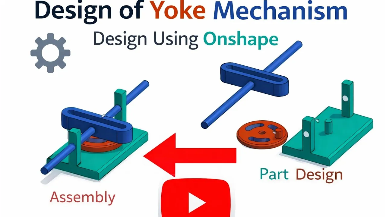
Scotch Yoke Mechanism: Converting Rotary to Linear Motion
177
The Scotch Yoke Mechanism is a simple mechanical device that converts circular rotation of a crank into reciprocating linear motion of a slider, producing pure sinusoidal motion (Simple Harmonic Motion) through a pin constrained within a straight slot in the yoke; it is commonly used in control valve actuators, shaping machines, and specialized pumps, though it may experience high wear at the pin-slot interface.
Click to watch →

🚀Conozca la Serie 98C: Compacto, Potente y Confiable | Bray Actuadores
19K
The Scottish Yoke Actuator Series 98C demonstrates key design principles for reliable valve automation: a non-pressurized central body minimizes air consumption by using all instrumentation air for actuation rather than filling the torque housing; fewer pressure seals enhance robustness and reduce leak risks; ISO 5211 mounting standards enable flexible installation with clockwise or counterclockwise fail-safe configurations; self-lubricating PTFE bushings and dry-film lubrication bearings ensure stable, efficient operation; and hardened chrome-plated cylinder and piston rod provide superior corrosion resistance for extended durability in demanding environments.
Click to watch →

Maior precisão com o atuador Scotch Yoke 🔴Bray Série 98
385
The Scotch Yoke actuator design provides precise linear motion conversion for valve automation through a sliding yoke mechanism that translates rotational input into linear output, offering high torque capacity (2,744 to 445,261 lb-in), modular configuration options across pneumatic, hydraulic, and electrohydraulic systems, and enhanced reliability through features like self-lubricating PTFE bearings, double wear bands, and corrosion-resistant components including chrome-plated cylinders and Tectyl-coated springs.
Click to watch →

Let's Build a Die Filer - Part 5, Scotch Yoke and Sheave!
145.8K
A scotch yoke is a space-efficient mechanism that converts rotary motion into linear motion. Its key advantage is tolerance to misalignment between the crankshaft axis and the linear motion axis, which is important when machining base castings where precise axis alignment is difficult to achieve.
Click to watch →
Deep Dive
Tribological analysis of the mechanism, focusing on sliding friction, wear patterns in the slot, and lubrication methods to mitigate mechanical wear.

Capitulo 1. Tribología
543
Tribology is the science studying the behavior of two surfaces in motion across three aspects: friction, wear, and lubrication. Friction is the force opposing sliding between contacting surfaces, caused by surface imperfections. Two types exist: sliding friction (direct surface contact without lubrication, as in pistons or dragging boxes) and rotational friction (surfaces rotating around their axes, as in bearings, producing 10 times less friction). Uncontrolled friction generates heat that can fuse metal parts together. Wear is material loss from surface rubbing, causing seal failure, pressure loss, and contaminant entry. To prevent wear, a minute separation between surfaces is essential. Lubrication achieves this by interposing substances (solid or liquid) that support loads and pressure while allowing mechanical work to continue. Analysis shows load reduction extends equipment life more effectively than speed reduction.
Click to watch →

Oil Analysis Part 1 Fundamentals
5K
Tribology encompasses the study of friction, wear, and lubrication between interacting surfaces, derived from Greek words meaning 'rubbing.' Surface asperities—microscopic peaks and valleys on seemingly smooth surfaces—are responsible for friction generation. Three main friction types exist: dry/solid friction (contact without lubricant), sliding friction (causes more wear due to larger surface area contact), and rolling friction (causes less wear). Fluid friction occurs internally within lubricants due to molecules of different sizes moving past each other. The coefficient of friction measures the force required to move a body divided by its weight. Six primary wear mechanisms affect machinery: abrasive wear (hard particles scraping surfaces), adhesive wear (surfaces momentarily weld together under high load), fatigue wear (repeated stress causing crack propagation), erosive wear (high-velocity particles in hydraulic systems), corrosive wear (chemical reactions like rust), and cavitation (collapsing air bubbles generating 20,000 PSI, pitting pump surfaces).
Click to watch →

Low Friction Doesn’t Equal Low Wear
675
Tribological testing uses block-on-ring tribometers with stationary blocks and rotating rings to measure friction under controlled loads. Wear scars are measured using white light interferometry to quantify volumetric wear. Testing engine oil versus ATF revealed different friction levels but similar wear, proving these properties are independent. Friction and wear can be controlled separately through surface finishes, coatings, and additive chemistry. This demonstrates that tribology allows engineers to optimize friction and wear independently for different applications, from engine protection to clutch performance.
Click to watch →

Friction and Wear, Solid solutions
9.6K
Wear is material loss during sliding contact. Three primary mechanisms exist: (1) Abrasive wear - hard particles bonded to one surface plough into softer material, dislodging it; (2) Adhesive wear - similar materials weld at asperities, and sliding fractures these junctions causing material loss from both surfaces; (3) Diffusion wear - atoms diffuse across junctions due to concentration gradients, causing mass transfer. The dominant mechanism depends on material properties, surface conditions, and operating environment.
Click to watch →

MOOHA Tribology Discussions on Additive Manufacturing with Dr. K. Anand
880
Wear is a multi-faceted problem occurring through multiple modes and mechanisms. Mechanical wear includes adhesive wear (when surface hardnesses are similar), abrasive wear (when one surface is much harder or sharp particles are present), fatigue wear, and fretting wear. Chemical wear includes corrosive wear and oxidation. Wear rates vary by 10^16 depending on operating conditions. Hydrodynamic lubrication shows minimal wear (15-25 microns), while boundary lubrication increases wear by a million times. No-lubrication conditions show 1,000-10,000 microns wear, and abrasion with harder particles increases wear by another factor of 10.
Click to watch →
Deep Dive
Multi-body dynamics simulation (MBD) using CAD/CAE tools to analyze joint forces, inertia, and vibration characteristics under high-speed operation.

Multibody Dynamics for PTC Creo for Simplified & Automated Flexible Body & Contact Modeling
396
Multibody dynamics (MBD) is a system-level analysis tool that couples kinematics, contacts, and multiphysics integrations to simulate complex mechanical systems; while CAD-embedded tools like Creo Mechanism provide basic functionality, dedicated MBD tools offer superior capabilities for contact-driven problems, flexible components, and multi-physics integrations through faster algorithms, more sophisticated contact handling, and better automation features, though transitioning requires addressing challenges like geometry cleanup, metadata loss, and revision control through specialized interfaces such as the Creo-RecurDyn interface extension.
Click to watch →
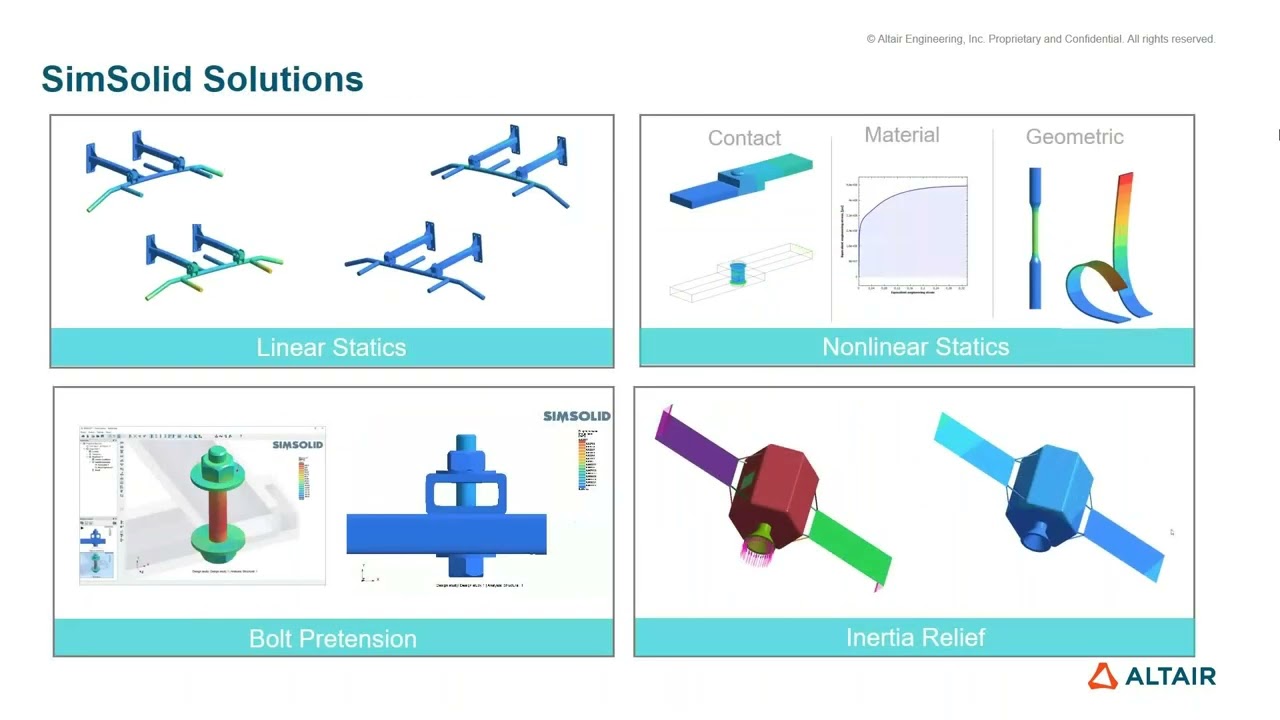
Advanced CAE Technology with AI simulation
425
Multibody Dynamics studies interconnected bodies with joints under external loads. The four-step process includes assembly (importing CAD, applying contacts/forces), solving (coupled with CFD, structural, and control systems), evaluation (using HyperView/HyperGraph for deformation, stress, strain, velocity, acceleration), and improvement (DOE and optimization). Automotive applications include electric vehicle development (Toyota case study comparing simulation vs experimental results), landing gear mechanism force analysis, engine simulation, and aircraft Conrad mechanism actuator sizing. Flux body generation enables stress/strain output during dynamic conditions using component mode synthesis.
Click to watch →

What is MSC Adams?
14.6K
MSC Adams is a multi-body dynamics simulation tool that enables engineers to model and analyze moving mechanical systems by progressively increasing model fidelity—from simple rigid body mechanisms to complex models incorporating flexible bodies, control systems, tires, and co-simulation with CFD and FEA, allowing early prediction of part behavior and loads during the virtual product development process.
Click to watch →

Vehicle Dynamics using Matlab & Adams Workshop | Skill-Lync
33.1K
Adams software enables multi-body dynamics simulation for suspension analysis, using joints, bushings, and hard points rather than CAD geometry. Simulations apply displacement inputs to study suspension travel profiles, revealing dynamic camber change and toe variations during compression and rebound. Visualization tools plot kinematic quantities like toe angle versus travel. Hard point sensitivity analysis demonstrates how small geometric changes (e.g., 10mm) substantially alter steering characteristics. Automated design studies enable systematic optimization of toe curves to achieve targeted understeer or oversteer behavior. This computational approach accelerates suspension development while maintaining engineering rigor. The methodology bridges theoretical understanding with practical application, enabling engineers to visualize and optimize suspension behavior before physical prototyping.
Click to watch →

Why It's So Hard (and Expensive) to Make Cars
138.8K
Multi-body dynamic (MBD) simulation models predict vehicle dynamics behavior by representing every structural and flexible member of the vehicle, including links, bushings, and tires. Chassis systems are mounted onto the body structure via rubber isolators or bushings, which require adequate body stiffness to function effectively. MBD models help define exactly how stiff the body structure needs to be to support the chassis system effectively. Engineers use these models to track wheel performance, tune stiffness and travel, and optimize suspension behavior while maintaining excellent road noise isolation through clever load path design.
Click to watch →
The Slider-Crank Dominance: Tribological and Efficiency Limitations of the Scotch Yoke
While the Scotch Yoke mechanism is praised for its compact size and ability to generate perfect simple harmonic motion, mechanical engineers often favor the classic slider-crank mechanism for practical, high-load applications. The primary criticism of the Scotch Yoke lies in its tribological performance. It relies on sliding contact between the pin and the yoke slot, which creates high contact pressures, rapid wear, and significant frictional losses. This necessitates continuous, high-performance lubrication and leads to frequent maintenance issues. Conversely, the slider-crank mechanism replaces this sliding joint with rotational bearings, which exhibit significantly lower friction, better heat dissipation, and superior longevity under heavy loads. Furthermore, while the Scotch Yoke produces a pure sine wave motion, the asymmetrical acceleration curve of a slider-crank can be advantageous in internal combustion engines by allowing more time for combustion near top dead center. Thus, from a reliability and efficiency standpoint, the slider-crank remains the industry standard, positioning the Scotch Yoke as a niche solution rather than a universal standard.
Basic kinematics of machines, including definitions of links, kinematic pairs, and degrees of freedom.
The distinction between linear (translational) and rotational motion, and how mechanical systems convert one to the other.
Fundamental concepts of Simple Harmonic Motion (SHM), specifically mathematical representations of sine and cosine displacement waves.
Introduction to the slider-crank mechanism to serve as a baseline comparison for reciprocating motion.
A comparative kinematic and dynamic analysis between the Scotch Yoke and the Slider-Crank mechanism, focusing on acceleration profiles and harmonic characteristics.
Real-world engineering applications of the Scotch Yoke, such as in control valve actuators, high-pressure gas compressors, and marine steam engines.
Tribological analysis of the mechanism, focusing on sliding friction, wear patterns in the slot, and lubrication methods to mitigate mechanical wear.
Multi-body dynamics simulation (MBD) using CAD/CAE tools to analyze joint forces, inertia, and vibration characteristics under high-speed operation.
730.5K views4.5Klikes2:10@SkylineTutorialsOriginal Release: 2016-01-06
the scotch yolk mechanism also known as slotted link mechanism is used to convert the linear motion of a slider into a rotational motion it can also be used to convert the rotational motion into a linear motion it consists of a slider or a piston a sliding yolk with a slot a disc-shaped crank with a [Music] pin the Piston or other reciprocating part is directly coupled to a sliding yolk with a slot that engages a pin on the rotating part when the crank rotates about a fixed axis the sliding yolk follows a l near path oscillating between the two extreme positions thus the rotational motion of the crank is converted into a linear motion of the Piston the advantages of this mechanism compared to a standard crankshaft and connecting rod setup are higher torque output with a small cylinder size fewer moving Parts enhance smoother operation higher percentage of the time spent at top dead center improving the engine [Music] efficiency the disadvantages are rapid wear of the slot in the yolk caused by sliding friction and high contact pressures lesser percentage of the time spent at bottom dead center reducing blow down time for two stroke engines [Music] what
Up Next

2:39
Earthquake Resonance: Building Seismic Response Model (Resonance 3)
@IRISEarthquakeScience
17.5K views•2009-11-09

30:21
Damped Free Vibration of Structures: Viscous Damping Theory
@IITKanpurNPTEL
23.4K views•2019-08-26

54:16
Polymer Environmental Degradation: Mechanisms & Stabilization
@iit
1.8K views•2012-07-10

33:39
How a Student's Question Saved a NYC Skyscraper from Collapse
@veritasium
22.8M views•2025-04-26
Related Study Plans & Knowledge Roadmaps
Structured learning paths in Engineering
engineering
Structural Dynamics (DIY TMDs & Shake Tables)
01Foundations of Structural Dynamics & Resonance
02Designing and Building a Motorized Shake Table
03Constructing the Scale Building & Tuned Mass Damper
+ 2 more learning modules
35h5 modules
Explore Roadmap
engineering
Building Acoustic Levitators: Physics & Arduino
01The Physics of Sound and Standing Waves
02Piezoelectric Transducers and H-Bridge Drivers
03Arduino Programming: Generating 40 kHz Signals
+ 2 more learning modules
14h5 modules
Explore Roadmap
engineering
Building Peltier Cloud Chambers: Particle Tracks
01Cosmic Rays & Cloud Chamber Physics
02Thermoelectric Cooling (TEC) Fundamentals
03Custom Liquid-Cooling Loop Design
+ 2 more learning modules
18h5 modules
Explore Roadmap
engineering
Yagi-Uda Antennas: Modeling, Build & VNA Test
01Introduction to RF and Antenna Fundamentals
02Yagi-Uda Antenna Design Principles
03Antenna Modeling and Simulation in 4NEC2
+ 2 more learning modules
18h5 modules
Explore Roadmap