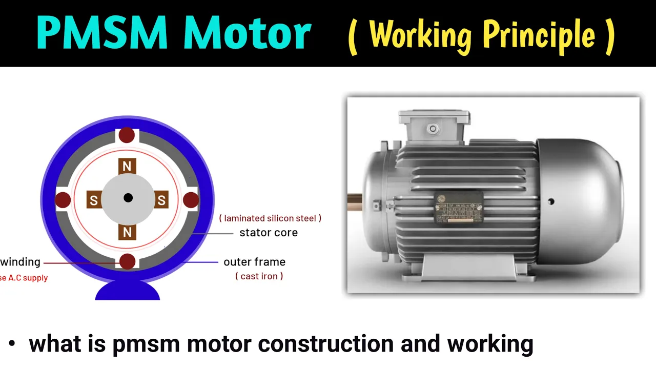
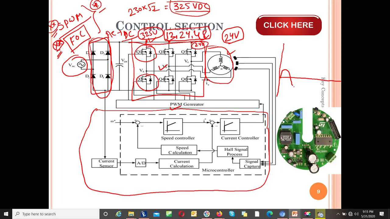
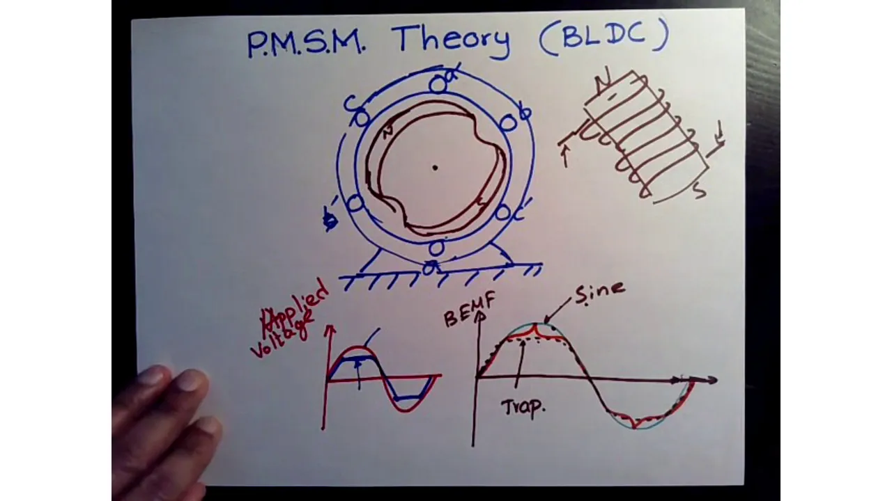


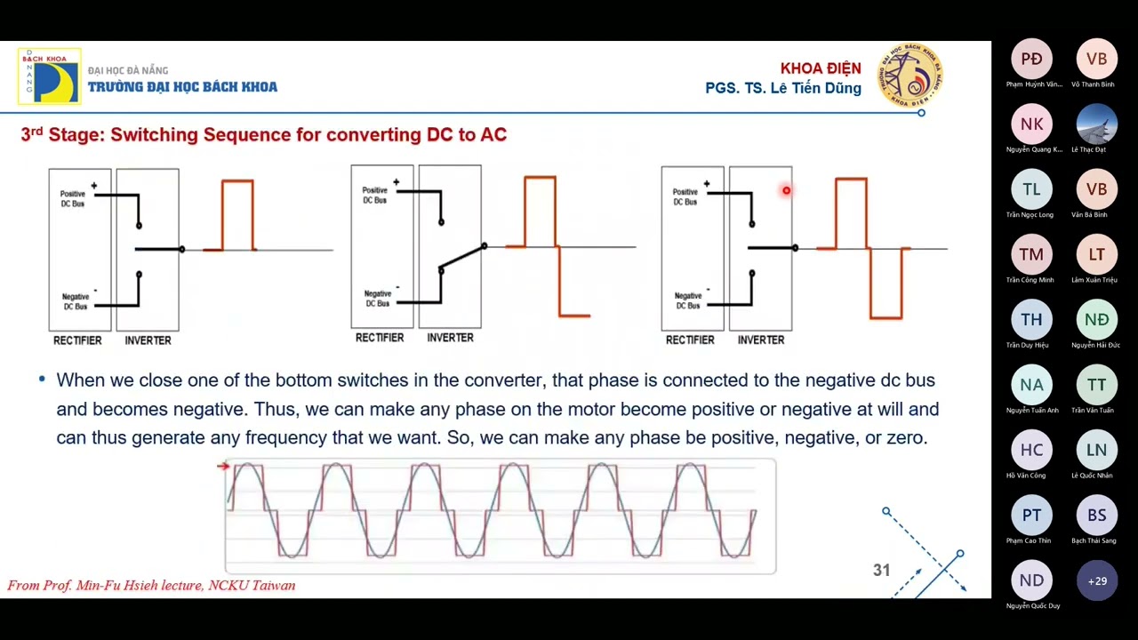
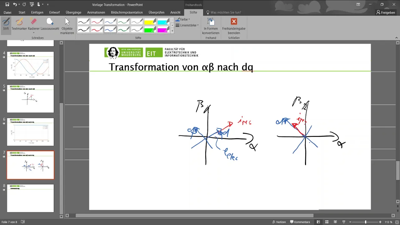









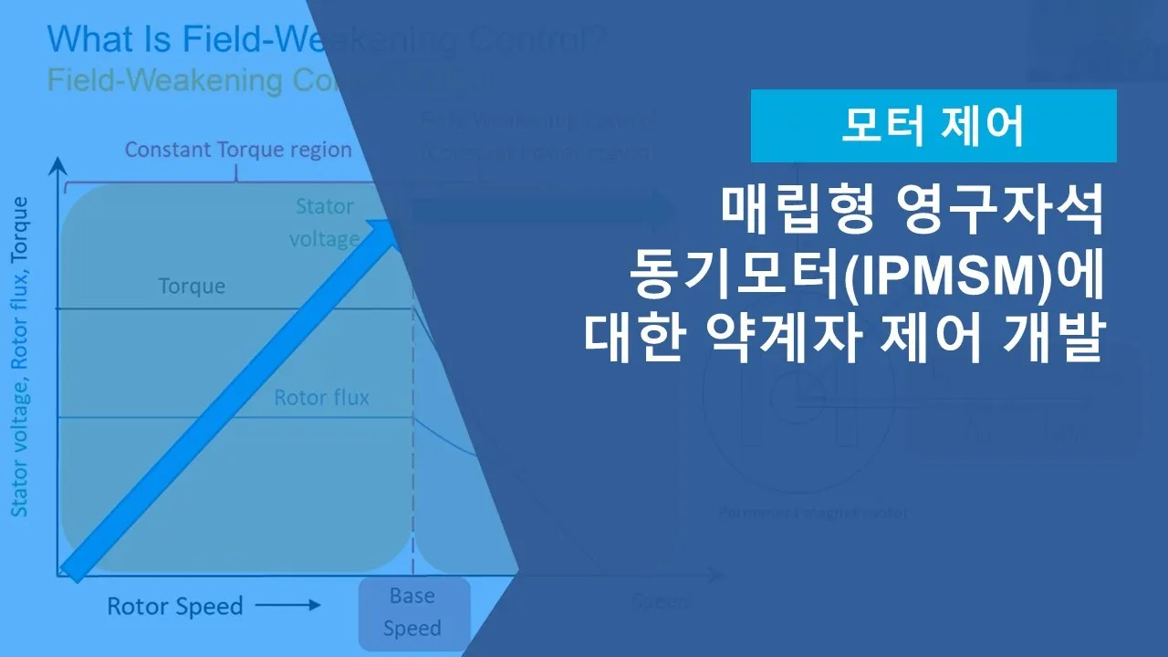




Field Oriented Control (FOC) is an efficient control technique for PMSM motors that transforms three-phase AC quantities (ABC frame) into two DC quantities (DQ frame) to simplify control; in torque control mode, the PI controller regulates IQ (torque component) based on acceleration pedal input while ID is maintained at zero, whereas in speed control mode, the controller regulates IQ based on the error between reference speed and actual motor speed, enabling precise speed regulation without direct throttle input.
Field-Oriented Control of PMSM: Speed vs Torque Modes
Added:Basic operational principles of Permanent Magnet Synchronous Motors (PMSM), including stator and rotor magnetic fields.
Fundamentals of coordinate transformations in electric drives, specifically the Clarke (abc to alpha-beta) and Park (alpha-beta to d-q) transformations.
Core feedback control concepts, particularly the structure and tuning of Proportional-Integral (PI) controllers used in current loops.
The fundamental mechanical relationships between torque, angular velocity, and power in rotating electrical machines.
Implementation of Field-Oriented Control (FOC) on microcontrollers or DSPs, including Space Vector PWM (SVPWM) generation.
Flux weakening and MTPA (Maximum Torque Per Ampere) control strategies to extend PMSM operation beyond base speeds.
Sensorless control methods for PMSM, using estimators and observers (e.g., Sliding Mode Observers) to eliminate physical encoders.
System-level electric vehicle (EV) drivetrain integration, focusing on regenerative braking control and traction control systems.
722 views25likes22:16Original Release: 2023-01-26
message we'll just have an overview about a speed mode or a top mode in electric vehicles and mostly will look the speed of talk mode for pmsm or the PLC Motors as all we know nowadays for electric two-wheelers or everywhere the pmsm and blec motors are very common and widely used see also for this Motors a very these motors are AC Motors and for this Motors the very famous and well-known technique for its control is the field oriented or shortly we'll call it as a FOC this is also it is efficient and because it is very efficient compared to others this becomes very popular and nowadays efficiency is one of the key factors if you go ahead [Music] then this particular architectures defines the FOC control you can see uh this is efficient control in the top model so we'll consider that we are getting a talk request from the acceleration parallel if it is a four wheeler you will have that acceleration parallel in the at the at the leg and if you are driving a two wheeler you will have in form of a throttle that is in hand so we are getting those acceleration inputs from those with respect to acceleration pedal or throttle and this will Define the actual talk which we require and this actual talk will be coming ahead with the major let me consider this IQ as a talk which is which is a proportional drop from the motor and then we have then after we have the pi controller and through the pi controller it is converting into uh by doing the clock transformation and we are getting the voltage v a bav NPC at the input of this Cloud for transformation we can have that VQ at this sphere and v d at at the end of this pi this VD and VQ are converted into VA VB VC and then those vabc as those are in analog form this VA pbnbc those will be converted into pwm pulses or we call as a space Factor pwm so let's consider that this particular space Factor pwm converts this analog form of voltage in two respective pwm signals and those pwm signals will be provided to the gate of the inverter as an inverter will have the igbts or the mosfets and which is driven by the gate and those Gates pwm signals will be controlled by this as we put on them and indirectly it is controlled by the voltage generated at the end of this transformation and then the finally the motor Will the three-phase AC motor will realize the voltage applied to the motor same way we have the input at year uh three phase v a i a i b i c which we need to convert into respect to ID and IQ so for that purpose we need to do a transformation which converts the ABC frame of reference to DQ frame of reference and same the inverse transformation which converts the DQ frame of reference to ABC frame of reference before going ahead into FOC control we need to understand what exactly the this the keyframe of reference and ABC frame of reference ABC framework reference is very obvious that we already know the three-phase motor will be driven by ABC so that's why those three phases are represented by vabc but what is this DQ frame of reference so to understand that let's assume a case that you are on a track a railway station and you are standing on a platform then there is a one person who is inside a train and the train is moving with a constant speed then you will see that that person is also moving with a constant speed as out of a train from the root foreign then you will see that previously the person who was going with a constant speed if you are inside a train you will see that that person is having a constant the position is a constant that is not moving now a becomes a stationary but when when you enter into the train that means if you change your location from platform to train you will see the perspective or the motion in the different form when your platform then you saw the person inside the train is moving at this particular speed as a frame and when you move inside the train and you saw that particular person is a stationary with respect to you now the next same concept we will put over here let's assume that you are on the stator now let's our thing is here we consider that the PMS mobile DC motor is rotor is at the center rotor is rotating and the stator which is the outer part of the motor which is fixed this is not rotating right so that is a that is a basic thing that I am assume that you all know so if you are on a stator then you saw the rotor is rotating with a particular speed it starts from zero angle if you take a particular point it will start from zero angle it will move to 90 then in 180 then 270 and 360 and it repeats so the rotor is rotating its all angles repetitively right and if Rotator is rotating repetitively with some particular frequency there is also a current which moves from the stator and as you know already there is a rotating magnetic field in the stator which caused the rotor to rotate which caused the rotor to rotate with the particular speed so as you increase the rotating magnetic field of the stator the respective you will observe the rotors speed rotating speed also will increase that rotors rotating magnetic field is the result of the rotor current that is a oh this these are AC Motors so the current are rotating with a particular frequency so this is like as when we are dealing with the pmsm motor there is a slight difference in PMs and blvc but right now we're not going into that we just want to restrict ourselves to this so let's assume that one more assumption that we are exciting our motor with sinusoidal voltage and the same way We Will We Will observe the current generated in the motor is also sinusoid in nature so let's have this particular current sinusoidal in nature with a particular frequency and we also saw previously our rotors rotating also with a particular frequency and these are proportional so as the rotating the the frequency of a current increase then the rotors speed also will increase so there is a relation that n s is equal to 120 F upon P that is why not written over here but uh that is the relation NS is the synchronous speed let's consider that the speed at this is the synchronous motor our rotor is rotating with the fixed speed that is NS and that particular rotating speed is depends on is equal to 120 F upon p p is number of poles right now forget about that so this equation will talk the rotor speed is proportional to F that is the frequency of the current as the current frequency increase the rotor speed also will increase now let's link a previous example of the oh train now suppose you are on a stator now look this all situation that's rotating rotor and oscillating current nature this is all we have saw when we are sitting on this data now let's jump on to the rotor when you jump onto the rotor what would be the situation here the situation will come back once you are on a rotor then with respect to you the rotor will be stationary right because you are also rotating with the photo so what you feel is rotor is stationary then you will see all parameters become constants and not in oscillator nature on the frequency right and that is just imagine just compare our previous example of a train with here right now on stator all terms are oscillating your voltage your current your rotor all are oscillating but once you jump on the rotor sorry on stator everything is oscillating with particular frequency but as you jump on the rotor the rotors motion becomes stationary because you are also rotating with the same speed of the rotor so as the rotors terms are stationary we also see the current voltage all terminology becomes stationary how as I said earlier 120 F upon p n s so it's proportional right so frequency increase this frequency also increase so both are proportional so now as the rotor speed is constant the rotors oscillating frequency is a constant then the status current that current oscillating term also becomes will be also become constant when you look from the rotors perspective okay that's all we saw we compared the create an example and we got the term all our constants why but why need to do that do I need to change our frame of reference from stator to rotor is there any specific need or it's just to make our system complicated not like that there is a very very very significant thing that we have to take care or we should know if we are controlling the oscillating terms or oscillating oscillating Behavior then it is very difficult to control it's not that easy to control and it is also proved mathematically that if you want if you are going to track something oscillating and something vibrant it's very difficult but if you are going to track which is not oscillating which is constant then it is easy to control right so that's why from control terminology when you are controlling something it is always prefer that you are your terminologies which are involved in the controls should be constant in nature then you will be controlling it very accurately nicely precisely right so that's why for SE Motors we are converting those AC waveform or AC Behavior into the DC Behavior and that will be possible when you change the the frame of reference from stator to rotor right so I think you understood the importance of change of frame of reference from state to rotor with this background if we go ahead then we will see the frame of reference that is in need of frame of reference change of frame of reference and why it is important so much important right I'm not going into dwell into like mathematical Parts which is shown over here uh but but I just explaining so to understand very properly the just idea what is the beauty of this one so for that reason what are the motors frame of reference that ABC frame of reference with the help of those Cloud part transformation we are converted into DQ frame of reference okay now now we have that DQ frame of reference so in that frame of reference the one term is ID and another term is IQ so I did term V for in our case is represents the uh the term which dealing with the flux in case of bldc motor or pmsm motor we are having we are having the magnet as the rotor so normally the ID term we need a reference ID term as zero in this particular session I will keep this as assumption and I will explain why ID need to be 0 in some letter discussion I will better say as a we will be doing some discussions and this IQ term is correspondingly represents the proportional term of torque so this will represent the equal IQ represents the top and ID represents the the field the field term over here so as the field is already excited by the magnets so the field component from the stator current we want to be zero so we're putting reference bar id id reference is zero ID reference as a zero so from this Transformations we need after the transformation ID to be regulated to 0 and IQ this we want to be regulated to the respective top which is received from the acceleration pedal or acceleration or the throttle right now I'm just considering that you already know the behavior of a pi and how Pi works then what are the difference comes from here that going through the pi this will generate VQ this will generate 3D so to maintain our ID 0 what we did required that will be calculated and to get that particular top how much VQ required that will be received over here so this IQ represents the equivalent term of the talk which is which which will be responsible uh responsible for the speed so over here you can see that directly we have a talk as a reference ID reference we are always making at zero there are some special conditions where ID could be negative but right now let's we will limit ourselves that ID reference we are keeping as a zero and then we are applying the torque which is received from acceleration pedal or throttle and those reference values it is comparing their difference error is calculated under error given to the pi and the pi is giving us the voltage VQ and V2 now we have voltage vqvd which are constant in nature so as like this will it will tell directly as suppose if you need higher talk then V Q should be higher if we need a lower torque then V Q should be lower so those are our constant terms but as we know this vdnbq those are the virtual voltages those are the virtual voltages of virtual modeling of the motor in router frame of reference so in reality those VT and VQ can be applied to actual motor so what is next definitely when we want to apply those voltages to the actual motor we need to convert those VD mvq to VA VB and VC and as I said earlier this vabc is the output of this inverse Cloud transformation so this video will be BBC analog in nature we need to convert into pwm those pwm should be given to the inverter and the inverter finally will try the bldc motor so this was in short the FOC architecture for the bldc or pmsm motor and uh also as a commuter earlier we need we'll discuss about the torque control more and the speed control mode so in torque control mode as we've seen normally most of the EVS which are controlled manually which are controlled with acceleration pedal and throttle are are always in torque control mode so the receives inputs from the acceleration pedal and then the further processing will be happening just like we are normally so it receives the the torque reference but the next is another is the speed control uh this is normally not used in the in general EVS but if you go for some autonomous vehicle where we want to control the speed of the vehicle as per the given commands then in that case we are not giving inputs to through some throttle we are providing some profiles of the voltage profiles of the speed or we want to give some reference speed just like I heard in one of the electric bike there is one Cruise mode where we can we are not giving inputs from the throttle we'll just picks a particular speed and vehicle will follow that particular speed so in that case it is in speed control mode not into the torque control mode so when you control the throttle it is the top control mode and when you given some reference of the speed and and the vehicle supposed to follow the reference speed just like in this case it's the Omega m r Omega normally represents the speed term then that that is called as a speed control mode so over here uh one more extra block will come into the picture that reference speed is uh subtracted from the uh subtracted from the Omega estimation what is Omega we calculated from the motor which is in feedback and this is actual Omega of the motor actual speed of the motor this is the reference P the error is calculated through the error it is given to the pi and the output of the pi is the reference IQ or we can also called as a reference talk because as we say the torque the IQR proportional term IQ represents the our IQ is proportional to the equivalent top of the motor so this is IQ reference so this is a reference talk and then again this further part is same as that of which we discussed earlier [Music] so we saw the speed mode control we saw talk more control we saw the requirement of ID IQ and why this transformation required so because of this FOC this Transformations FOC can able to control properly even though we have a non-linear nature of the voltages and speed right so that's all for today thanks for your attention thank you
Up Next

15:49
Implementing Haptic Feedback with SimpleFOC on a Brushless Gimbal Motor
@JesseSchoch
17.9K views•2020-12-07

30:32
Ultrasonic Transducers: Resonant Frequency Measurement and Horn Design
@imajeenyus42
229.9K views•2017-02-22

54:16
Polymer Environmental Degradation: Mechanisms & Stabilization
@iit
1.8K views•2012-07-10

33:39
How a Student's Question Saved a NYC Skyscraper from Collapse
@veritasium
22.8M views•2025-04-26
Related Study Plans & Knowledge Roadmaps
Structured learning paths in Engineering
engineering
Building Acoustic Levitators: Physics & Arduino
01The Physics of Sound and Standing Waves
02Piezoelectric Transducers and H-Bridge Drivers
03Arduino Programming: Generating 40 kHz Signals
+ 2 more learning modules
14h5 modules
Explore Roadmap
engineering
Building Peltier Cloud Chambers: Particle Tracks
01Cosmic Rays & Cloud Chamber Physics
02Thermoelectric Cooling (TEC) Fundamentals
03Custom Liquid-Cooling Loop Design
+ 2 more learning modules
18h5 modules
Explore Roadmap
engineering
Yagi-Uda Antennas: Modeling, Build & VNA Test
01Introduction to RF and Antenna Fundamentals
02Yagi-Uda Antenna Design Principles
03Antenna Modeling and Simulation in 4NEC2
+ 2 more learning modules
18h5 modules
Explore Roadmap
engineering
ECG Monitor Design: Op-Amps, Filters & Noise
01Electronics & Breadboard Basics
02Op-Amps and Instrumentation Amplifiers
03Bioelectricity and ECG Fundamentals
+ 2 more learning modules
18h5 modules
Explore Roadmap