AC to DC voltage rectification converts alternating current (AC) to direct current (DC) using diodes, which allow current to flow in one direction while blocking it in the opposite direction; a single diode creates half-wave rectification with zero voltage half the time, while a full-wave rectifier using four diodes ensures continuous current flow, and adding a capacitor smooths the output voltage to maintain constant levels.
AC to DC Rectification: Half-Wave vs Full-Wave Explained
Added:Deep Dive
Understanding the fundamental differences between Alternating Current (AC) and Direct Current (DC), including frequency, polarity, and waveform cycle.

What's AC and DC? What are the Differences between Alternating Current and Direct Current?
68.1K
Alternating Current (AC) reverses direction periodically, creating positive and negative polarity cycles represented by sine waves. Direct Current (DC) flows unidirectionally without reversing. The sine wave represents circular motion converted to two-dimensional coordinates, with electrons moving from 0° to 90° (positive peak), 180° (zero crossing), 270° (negative peak), and back to 360°. The flicker fusion threshold explains why 60 Hz power appears constant to human vision, as our brains cannot perceive rapid pulsing at this frequency.
Click to watch →

It's Time To Get Weird!
56.8K
Alternating current (AC) is electricity that flows in one direction for half of its cycle period and in the opposite direction for the other half, constantly changing polarity. Direct current (DC) always flows in the same direction. The frequency of AC determines how often the waveform repeats per second, with 50 Hz meaning the current switches direction 50 times per second. This fundamental distinction between AC and DC is essential for understanding electrical systems and their applications.
Click to watch →

AC(교류) DC(직류) 모르면 안됩니다 AC (alternating current) DC (direct current) must be known
53.1K
AC (Alternating Current) is an electrical current whose magnitude and direction change periodically over time, with frequency measured in Hz (typically 50-60 Hz), while DC (Direct Current) flows in one direction with constant polarity; AC has impedance (Z = √(R² + X²)), power factor between 0-1, and various waveforms (sine, square, triangular), whereas DC has only resistance, power factor of 1, and produces pulsating waves; AC is generated by power plants for household outlets, while DC comes from batteries.
Click to watch →

AC #03 - Tipos de Corrente Alternada
60.6K
The fundamental distinction between alternating current (AC) and direct current (DC) lies in the presence or absence of polarity reversal. A waveform is classified as AC only when it crosses the zero axis, changing from positive to negative and vice versa during its cycle. If a waveform remains entirely above or entirely below the zero axis without crossing, it represents direct current even if it has varying amplitude (such as a sinusoidal or triangular wave that never crosses zero). The key criterion is whether the current direction reverses periodically.
Click to watch →

L-1, परिचय, अध्याय-7, प्रत्यावर्ती धारा | Alternating Current | Class-12th Physics | कक्षा-12 भौतिक
74.8K
DC (Direct Current) flows with fixed polarity, always in one direction. The graph stays on one side of the time axis. Pure DC has constant magnitude. AC (Alternating Current) has both magnitude and direction changing with time. The graph crosses the time axis showing positive and negative values. In India, AC has 50 Hz frequency, completing 50 cycles per second. In one cycle, current reaches maximum twice and becomes zero twice, meaning bulbs glow 100 times and go dark 100 times per second.
Click to watch →
Deep Dive
The operating principle of a semiconductor P-N junction diode, specifically its unidirectional current-carrying behavior under forward and reverse bias.

Working of P-N Junction Diode in Forward Biasing and Reverse Biasing ..Semiconductor Electronics..
4.6K
A P-N junction diode conducts current differently under forward and reverse bias. In forward bias (positive to P-side, negative to N-side), majority carriers flow toward the junction, narrowing the depletion layer and reducing barrier potential to V - V_applied. When applied voltage exceeds barrier potential, significant forward current flows (mA range) with low resistance. In reverse bias (positive to N-side, negative to P-side), majority carriers are pulled away, widening the depletion layer and increasing barrier potential to V + V_applied. Only a small reverse current flows due to minority carriers (μA range). If reverse voltage exceeds the Zener breakdown voltage, the junction breaks down, causing sudden large current that can damage the diode.
Click to watch →

Semiconductors L10: Forward bias and Reverse Bias | p-n junction diode | Physics Endgame
19.9K
In a p-n junction diode, forward bias occurs when the positive terminal of an external voltage source is connected to the p-side and the negative terminal to the n-side, reducing the barrier potential and allowing majority carriers to flow across the junction, resulting in significant current; reverse bias occurs when the polarity is reversed, increasing the barrier potential and blocking majority carrier flow while only allowing minimal minority carrier current to pass, making the diode act as a unidirectional conductor.
Click to watch →

Lec 13_PN junction diode | Physics | First year engineering
248
Forward bias occurs when p-type connects to positive and n-type to negative battery terminals, canceling the potential barrier by repelling majority carriers toward the junction. The depletion layer reduces and eliminates at threshold voltage, allowing current flow due to majority carriers. Reverse bias connects p-type to negative and n-type to positive, increasing the potential barrier and widening the depletion layer. The diode acts as an open circuit with only a small leakage current from minority carriers. This unidirectional conduction is the fundamental operating principle of PN junction diodes.
Click to watch →

PN JUNCTION DIODE | FORWARD AND REVERSE BAIS | NCVT | 2 YEAR | ELECTRICIAN
174
A PN junction diode conducts current only in forward bias. In forward bias, P-type connects to positive battery terminal and N-type to negative, reducing the depletion region and allowing majority carriers to cross. In reverse bias, P-type connects to negative and N-type to positive, widening the depletion region and blocking current. This bidirectional behavior—conducting like a conductor in forward bias and blocking like an insulator in reverse bias—is the fundamental property that makes semiconductors useful in electronic circuits.
Click to watch →

npn과 pnp트랜지스터의 동작원리와 차이
122.1K
A PN junction diode conducts current when forward-biased (P-type connected to positive, N-type to negative) and blocks current when reverse-biased. In forward bias, electrons move from N-type to P-type, creating current flow. In reverse bias, the diode acts as an open circuit. This unidirectional conduction property is fundamental to semiconductor devices and forms the basis for rectification circuits that convert AC to DC.
Click to watch →
Deep Dive
Basic AC circuit concepts, such as sinusoidal waveforms, peak voltage (Vp), and root-mean-square (RMS) voltage.

مفاهيم أساسية في الهندسة الكهربائية
165.3K
AC waveforms have several key parameters: Peak voltage (V_peak) is the maximum value the waveform reaches. RMS (Root Mean Square) voltage is the effective value that produces the same heating effect as DC voltage. For a sinusoidal AC waveform, the relationship is: V_peak = V_rms × √2. For example, household AC voltage is typically 220V RMS, which corresponds to approximately 311V peak (220 × 1.414 ≈ 311). The RMS value is the value actually used for practical calculations and power delivery.
Click to watch →

Circuitos, eletromagnetismo e máquinas (Q04 e Q05- Petrobras/Cebraspe) - Vef e correção de FP
110
This segment covers essential AC circuit calculations. Key values to memorize: √2 ≈ 1.42 and √3 ≈ 1.73. The RMS (effective) voltage equals peak voltage divided by √2, while peak voltage equals RMS voltage multiplied by √2. For sinusoidal waveforms, peak voltage is always greater than RMS voltage. The RMS concept emerged from the historical Edison vs. Tesla/Westinghouse debate about AC vs. DC systems. RMS voltage is defined as the DC voltage that would dissipate the same power in a resistor as the AC voltage. A 14V peak voltage corresponds to approximately 10V RMS (14 ÷ 1.42 ≈ 10).
Click to watch →

Curentul alternativ
12.5K
This section covers three critical voltage measurements in AC circuits. Peak voltage (Vp) is the maximum value from zero to the peak. Peak-to-peak voltage (Vpp) is the total range between maximum positive and negative peaks (twice the peak voltage for sine waves). RMS voltage (Root Mean Square) is the effective voltage that produces equivalent heating in a resistor as DC. For sinusoidal AC, RMS equals peak voltage divided by √2 (approximately 0.707 times peak).
Click to watch →

3° Aula Eletrônica Básica
737
The peak value (VP) is the maximum magnitude of the AC waveform from zero to the highest or lowest point. The peak-to-peak value (Vpp) is the total voltage difference between maximum positive and negative peaks, equal to twice the peak value for a perfect sine wave. The average value of a complete AC cycle is zero due to positive and negative areas canceling. The RMS (Root Mean Square) value represents the effective DC value producing equivalent power dissipation. For a perfect sinusoidal waveform, RMS = VP/√2 (approximately VP × 0.707). This explains why a 220V AC outlet has a peak voltage of approximately 311V (220 × √2).
Click to watch →

مبادئ التيار المتناوب AC
15.1K
This section covers the essential values and power concepts in AC circuits: (1) Peak value (Vmax) is the maximum amplitude from zero. (2) RMS value (Vrms) is the effective value calculated as Vmax/√2 ≈ 0.707 × Vmax, producing equivalent heating effect as DC. (3) Average value (Vavg) is 0.637 × Vmax. (4) Peak-to-peak value (Vpp) is 2 × Vmax. (5) For power calculations, DC uses P = V × I, while AC uses RMS values. (6) The general AC equation is v = Vmax × sin(ωt ± θ). (7) Household voltage ratings (220-230V) are RMS values, not peak values. (8) Power factor (cosθ) represents the efficiency of power usage. These concepts are essential for understanding AC circuit behavior and performing accurate power calculations.
Click to watch →
Deep Dive
Fundamental electrical laws, such as Ohm's Law and Kirchhoff's Voltage Law (KVL), to trace current flow in simple loops.
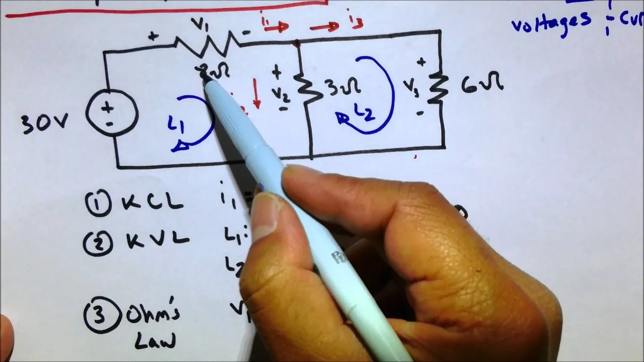
KVL KCL Ohm's Law Circuit Practice Problem - (Electrical Engineering Fundamental and Basics Review)
902.2K
Three fundamental laws govern electrical circuit analysis: Kirchhoff's Current Law (KCL) states that current entering a node equals current leaving it (I1 = I2 + I3); Kirchhoff's Voltage Law (KVL) states that the algebraic sum of voltages around any closed loop equals zero (+30V - V1 - V2 = 0 for Loop 1, V3 - V2 = 0 for Loop 2); and Ohm's Law relates voltage, current, and resistance (V = IR) for each resistor. Together, these laws provide the mathematical framework for analyzing complex circuits.
Click to watch →

Kirchhoff's Laws: by Dr. C. B. Bangal
557.2K
Kirchhoff's Voltage Law (KVL), also called the loop law or mesh law, states that for any closed loop in a circuit, the sum of all potential rises equals the sum of all potential drops. A closed loop is any continuous path that starts and ends at the same point. When traversing a loop: moving with current through a resistor causes a potential drop (-IR), moving against current causes a potential rise (+IR); moving from negative to positive terminal of a battery causes a potential rise (+V), moving from positive to negative causes a potential drop (-V).
Click to watch →
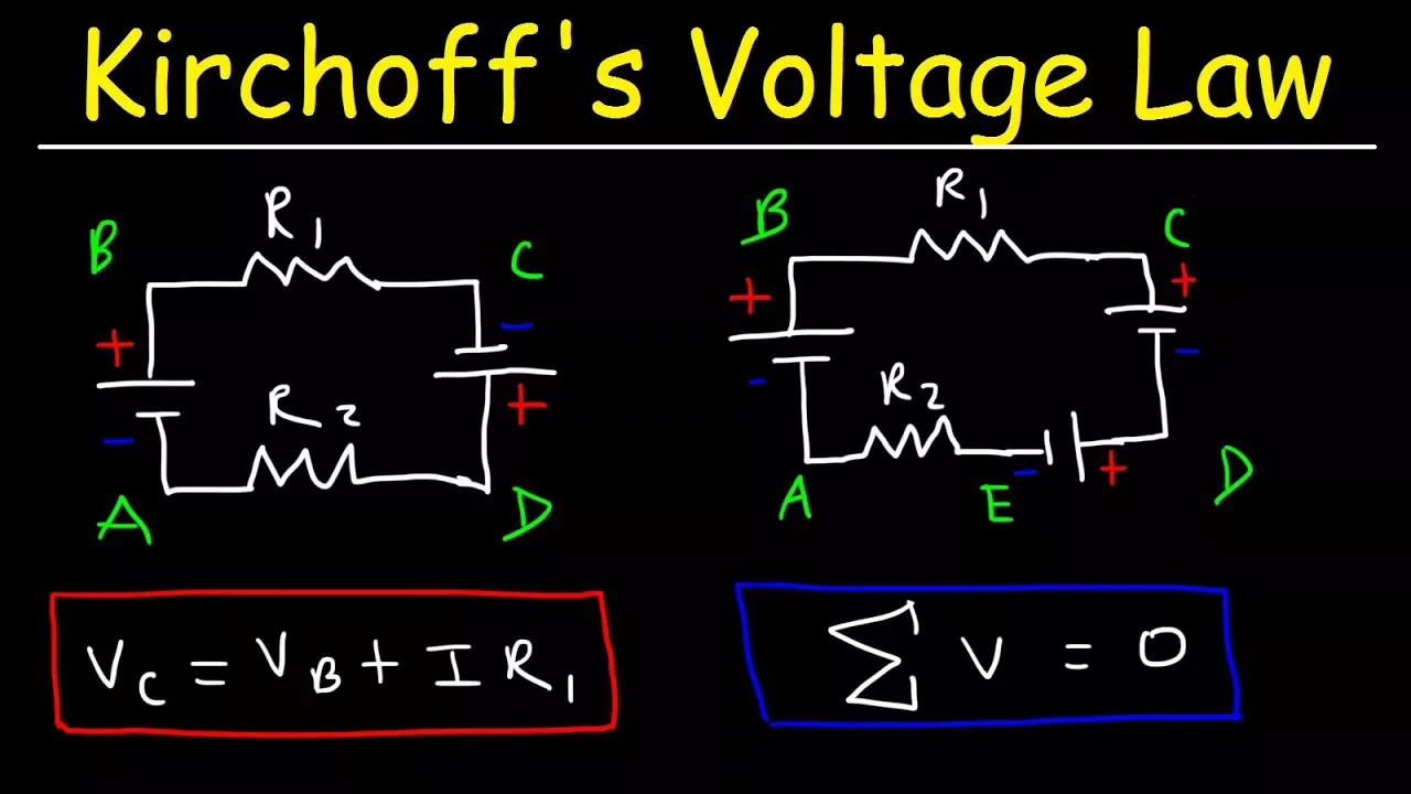
Kirchhoff's Voltage Law - KVL Circuits, Loop Rule & Ohm's Law - Series Circuits, Physics
2M
Kirchhoff's Voltage Law (KVL) states that the algebraic sum of all voltages around any closed loop in a circuit must equal zero; when applying KVL, assign negative voltage to resistors (which always consume energy and create voltage drops) and assign positive or negative voltage to batteries based on current direction—positive when current flows from low to high potential (battery supplying energy) and negative when current flows from high to low potential (battery acting as a load)—then use Ohm's Law (V=IR) to calculate unknown quantities like current or voltage drops across components.
Click to watch →

LEC-04 OHMS LAW ,KCL, KVL (ओह्म्स लॉ, केसीएल, केवीएल) by RAMAN SIR
15.4K
Ohm's Law states that the voltage across a conductor is directly proportional to the current flowing through it, provided temperature remains constant (V = IR). Kirchhoff's Current Law (KCL) states that at any junction in an electrical circuit, the algebraic sum of currents entering equals the algebraic sum of currents leaving. Kirchhoff's Voltage Law (KVL) states that the algebraic sum of all voltages in any closed loop equals zero. These fundamental laws form the basis for analyzing electrical circuits.
Click to watch →
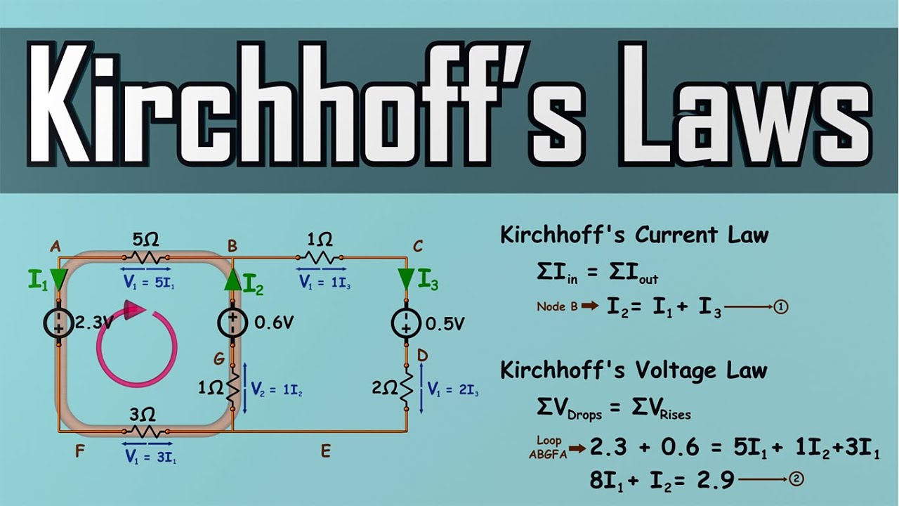
Kirchhoff's Laws - How to Solve a KCL & KVL Problem - Circuit Analysis
350.5K
Kirchhoff's Current Law (KCL) states that the total current entering a junction equals the total current leaving it, representing conservation of charge; Kirchhoff's Voltage Law (KVL) states that the total voltage drop around any closed loop equals the total voltage rise, representing conservation of energy. Together with Ohm's Law, these laws provide a systematic framework for analyzing complex electrical circuits by labeling nodes, assigning currents, writing KCL equations for nodes with three or more branches, and KVL equations for independent loops, then solving the resulting system of simultaneous equations to find unknown currents and voltages.
Click to watch →
Prerequisite Knowledge
- Concept 01Understanding the fundamental differences between Alternating Current (AC) and Direct Current (DC), including frequency, polarity, and waveform cycle.
- Concept 02The operating principle of a semiconductor P-N junction diode, specifically its unidirectional current-carrying behavior under forward and reverse bias.
- Concept 03Basic AC circuit concepts, such as sinusoidal waveforms, peak voltage (Vp), and root-mean-square (RMS) voltage.
- Concept 04Fundamental electrical laws, such as Ohm's Law and Kirchhoff's Voltage Law (KVL), to trace current flow in simple loops.
Subsequent Learning
- Step 01Analyzing and implementing filter circuits (using capacitors or inductors) to minimize ripple voltage and smooth the pulsating DC output.
- Step 02The study of DC voltage regulation, incorporating Zener diodes or linear regulators (e.g., 78xx series) to achieve a stable DC output despite load changes.
- Step 03Calculating performance parameters of rectifiers, including rectification efficiency, ripple factor, and Transformer Utilization Factor (TUF).
- Step 04Exploring advanced power conversion systems, such as Switched-Mode Power Supplies (SMPS) and three-phase rectification for industrial applications.
AC to DC
Diode Solution
Forward Block
Single Diode
Four Diodes
Capacitor Boost
Rectifier Done
AC to DC
0:09Playing Section
- 1
Household power arrives as alternating current, constantly shifting direction.
- 2
Most electronics need direct current, flowing steadily in a single direction.
Active (Synchronous) Rectification
While traditional half-wave and full-wave rectifiers rely on passive diodes, they suffer from inherent efficiency losses due to the diode's forward voltage drop (typically 0.7V for silicon). In modern power electronics, Active Rectification (or synchronous rectification) serves as a critical alternative. This approach replaces passive semiconductor diodes with actively controlled switches, such as MOSFETs. By dynamically switching these transistors on and off in synchronization with the AC waveform, the voltage drop is drastically reduced. This minimizes power dissipation, reduces heat generation, and significantly increases overall energy efficiency, making it the preferred choice for low-voltage, high-current applications where standard passive rectifiers are too inefficient.
Deep Dive
Analyzing and implementing filter circuits (using capacitors or inductors) to minimize ripple voltage and smooth the pulsating DC output.

Filter Circuits-L, C, LC, CLC
59K
Filter circuits convert pulsating DC from rectifiers into smoother DC by using capacitors (which block DC and pass AC ripples), inductors (which oppose current changes), or combinations thereof; the ripple factor quantifies filtering effectiveness, with values ranging from approximately 1.05 for simple capacitor filters to much lower values for advanced LC and CLC (pi) filters, where higher values of inductance and capacitance generally result in better ripple reduction.
Click to watch →

अध्याय-14, अर्द्धचालक इलेक्ट्रॉनिकी | One Shot Revision | Class-12th Physics | कक्षा-12 भौतिकी
142.2K
Filter circuits smooth the pulsating DC output from rectifiers to produce more constant DC voltage. A capacitor filter charges when voltage is high and discharges when voltage is low, reducing ripple. The ripple voltage depends on capacitance, load resistance, and frequency. An inductor filter resists current changes, blocking AC components. An RC filter combines both. The ripple factor is the ratio of RMS ripple voltage to DC output voltage. Lower ripple factors indicate better filtering. These circuits are essential for power supply applications.
Click to watch →

ANALOG SYSTEMS AND APPLICATIONS: Ripple and Filters
1.8K
Filters remove AC ripple from rectifier output. Capacitor filters use X_C = 1/(ωC): block DC (X_C → ∞) while allowing AC to pass through, charging during peaks and discharging through load during valleys. Inductor filters use X_L = ωL: allow DC (X_L = 0) while opposing AC flow. Both filter types smooth pulsating DC to produce cleaner output, with capacitor filters being more common due to simpler construction and lower cost.
Click to watch →

Semiconductor devices full chapter in one video | class 12 physics | NEET I CUET | sachin sir
26.7K
Filter circuits smooth the pulsating DC output from rectifiers to produce a more constant DC voltage. Capacitor filters use a capacitor connected in parallel with the load. The capacitor charges during voltage peaks and discharges during voltage troughs, reducing ripple. Inductor filters use an inductor in series with the load, which resists changes in current. The choice between capacitor and inductor filters depends on the application requirements and the frequency of the ripple.
Click to watch →
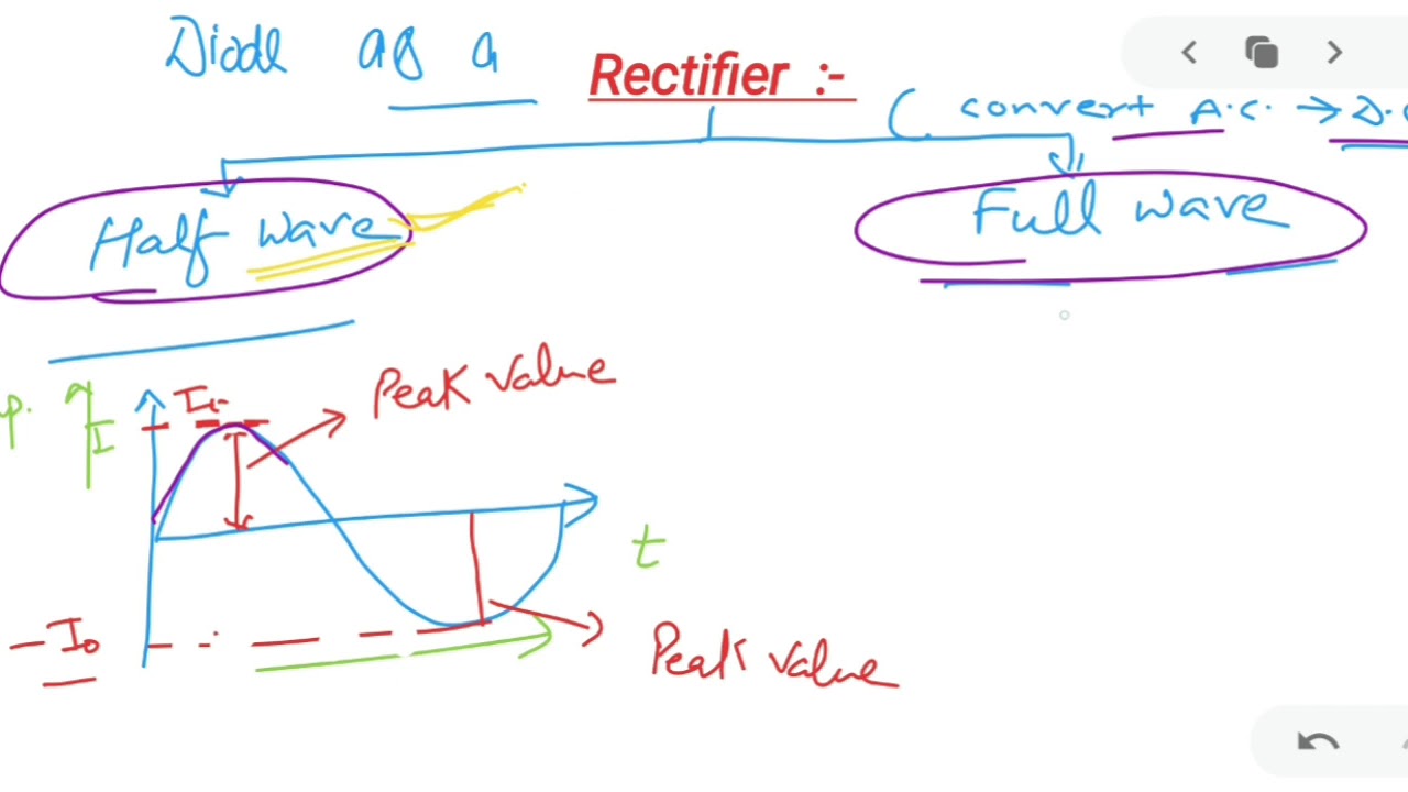
Class 12 Semiconductor (Rectifier) Part 2
124
Filter circuits are used to remove the ripple voltage from the pulsating DC output of a rectifier, converting it to pure DC. There are three main types of filter circuits: (1) Capacitor filter - uses a capacitor to smooth the output, (2) Inductor filter - uses an inductor to smooth the output, and (3) LC filter - uses both an inductor and a capacitor together for better ripple reduction. Filter circuits are connected in parallel with the load and help convert the fluctuating DC output into a steady DC voltage suitable for electronic applications.
Click to watch →
Deep Dive
The study of DC voltage regulation, incorporating Zener diodes or linear regulators (e.g., 78xx series) to achieve a stable DC output despite load changes.
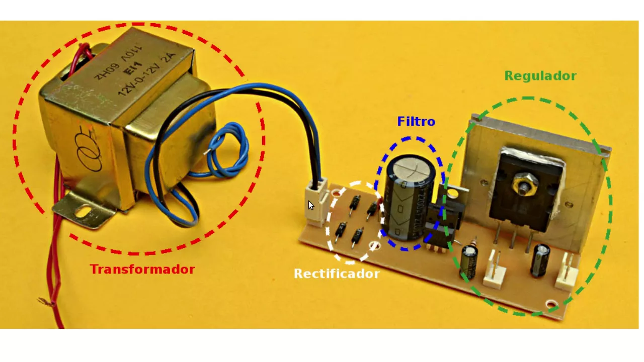
Fuente Lineal
293.4K
The regulation stage maintains stable output voltage regardless of load changes. The 78xx series provides positive voltage regulation (e.g., 7805=5V, 7809=9V, 7812=12V, 7815=15V, 7824=24V), while 79xx series provides negative voltage regulation. The 'xx' indicates output voltage. Input voltage must exceed desired output voltage. The 7805 handles up to 1.5A; currents above 1A require heat sinks. Both series maintain constant output regardless of input variations or load changes, providing stable power for electronic devices.
Click to watch →
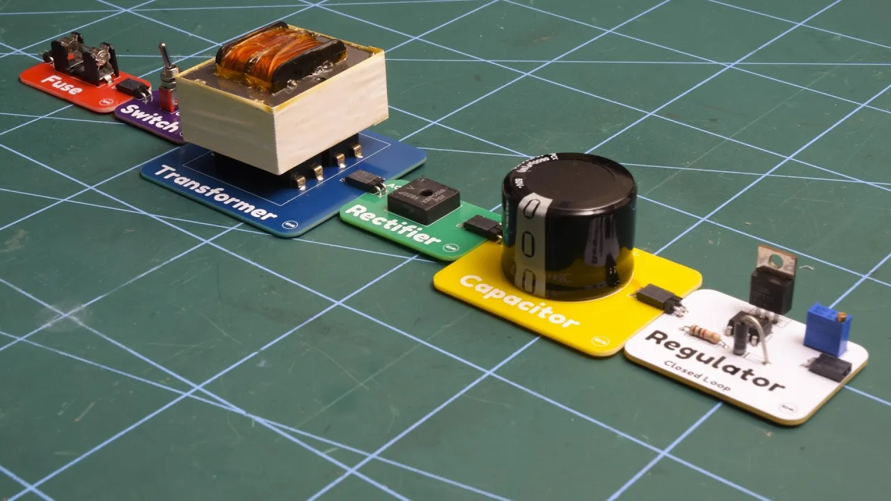
Linear Power Supply Components Explained: A Full Build Guide
641K
A linear power supply converts AC mains voltage to stable DC output through five key stages: (1) Mains input with fuse for safety protection, (2) Transformer for voltage reduction and electrical isolation, (3) Full-wave bridge rectifier to convert AC to pulsating DC, (4) Capacitor to smooth the DC output and reduce ripple, and (5) Closed-loop linear regulator using a Zener diode and op-amp feedback to maintain constant output voltage regardless of input variations or load changes.
Click to watch →

Complete Class 12th Physics | 100 Marks Confirmed 🔥 | NEET 2025 | Yawar Manzoor
48K
A Zener diode is used as a voltage regulator. When connected in reverse bias with a load, it maintains a constant voltage (Zener voltage, V_Z) across the load regardless of changes in input voltage or load resistance. Different Zener diodes are available with different Zener voltages (e.g., 10V, 20V). In a Zener diode voltage regulator circuit: the Zener diode maintains constant voltage V_Z across the load; the current through the Zener diode is I_Z = (V_in - V_Z)/R, where R is the series resistance; the load current is I_L = V_Z/R_L. When V_in < V_Z, the Zener diode is off and V_out = V_in; when V_in ≥ V_Z, the Zener diode conducts and V_out = V_Z (constant).
Click to watch →

SEMICONDUCTOR ELECTRONICS in ONE SHOT || All Concepts, Tricks & PYQ || Ummeed NEET
254.5K
Zener diodes operate in reverse breakdown to maintain constant voltage. In heavily doped junctions, Zener breakdown occurs when the electric field breaks covalent bonds directly. The Zener voltage (Vz) remains constant regardless of current, making Zener diodes ideal voltage regulators. In a regulator circuit with series resistor, the load voltage equals Vz, and excess current flows through the Zener. The current through the Zener is Iz = (Vs - Vz)/R - IL, where IL is load current.
Click to watch →

JEE Main 2026 Complete Physics in One Shot 🔥 Final Revision (Part 2) | January Attempt | Abdul Sir
82.3K
A Zener diode regulates voltage when connected in reverse bias. Load current IL = VZ/RL, where VZ is Zener voltage and RL is load resistance. Total current from source is I = (V - VZ)/R, where R is series resistance. Zener current is IZ = I - IL. For example, with VZ = 10V, RL = 1500Ω, and V = 15V, IL = 10/1500 = 6.67mA and IZ = (15-10)/500 - 6.67mA = 3.33mA.
Click to watch →
Deep Dive
Calculating performance parameters of rectifiers, including rectification efficiency, ripple factor, and Transformer Utilization Factor (TUF).

Power Electronics | K-Notes Series | GATE 2023 | Ankit Goyal
13.4K
Key rectifier performance parameters include: Form factor (FF) = V_rms / V_avg, Ripple factor (RF) = √(FF² - 1), Transformer utilization factor (TUF) = P_dc / (V_rms × I_rms), Rectification efficiency (η) = P_dc / (V_rms × I_rms), and Input power factor (PF) = P_dc / (V_rms × I_rms). For half-wave rectifier with resistive load: V_avg = V_m / π, V_rms = V_m / 2, FF = π/2 ≈ 1.57, η = 40.6%.
Click to watch →

Single Phase Half Wave Rectifier | L:3 | Power Electronics | GATE 2021 Ummeed Crash Course
36.8K
Rectification efficiency measures how effectively a rectifier converts AC power to DC power. It is calculated as: η = (Vdc × Idc) / (Vrms × Irms) × 100%. Transformer Utilization Factor (TUF) measures how effectively the transformer's rating is utilized: TUF = (Vdc × Idc) / (Vrms × Isupply_rms). Higher TUF indicates better utilization of transformer capacity. These parameters are essential for evaluating rectifier circuit performance.
Click to watch →

Day 07 Rectifier Complete Analysis One Shot | DRDO CEPTAM-11 Tech-A Electronics By Rakesh Verma
226
Rectifier efficiency is the ratio of DC output power to AC input power. Half Wave Rectifier efficiency is 40.6%, while Full Wave Rectifier efficiency is 81.2%. Ripple factor indicates AC content in DC output. Half Wave Rectifier has ripple factor 1.21, while Full Wave Rectifier has 0.48. Lower ripple factor means smoother DC output. Transformer Utilization Factor (TUF) measures transformer capacity utilization: 21% for Half Wave, 69.3% for Center Tapped Full Wave, and 81.2% for Bridge Rectifier.
Click to watch →

Problems on Single Phase Half Wave Controlled Rectifiers | Power Electronics | Lecture 42
18.2K
This segment covers the key performance parameters for controlled rectifiers with resistive loads. Rectification efficiency η = (V_out_avg / V_out_rms)² × 100% is calculated as 24.28% for α = π/3. Form Factor = V_out_rms / V_out_avg = 2.033, and Ripple Factor = √(Form Factor² - 1) = 1.77. Transformer Utilization Factor TUF = P_DC / (V_s × I_s) = 16.6%. The Peak Inverse Voltage (PIV) across the SCR equals the peak supply voltage VM. These parameters provide a complete characterization of rectifier performance.
Click to watch →

L-06 | Single Phase Rectifiers Part-02 | Power Electronics | Crash Course | GATE 2026 | Ankit Goyal
2.4K
Key performance parameters for rectifiers include: Form Factor = RMS voltage / Average voltage (closer to 1 indicates better DC output); Ripple Factor = Harmonic RMS / Average output = √(Form Factor² - 1) (lower is better); Distortion Factor = Fundamental RMS / Total RMS; Total Harmonic Distortion (THD) = √(1/G² - 1); Input Power Factor = G × FDF (for sinusoidal input); Rectification Efficiency = (V_average × I_average) / (V_RMS × I_RMS); Transformer Utilization Factor (TUF) = DC output power / VA rating.
Click to watch →
Deep Dive
Exploring advanced power conversion systems, such as Switched-Mode Power Supplies (SMPS) and three-phase rectification for industrial applications.
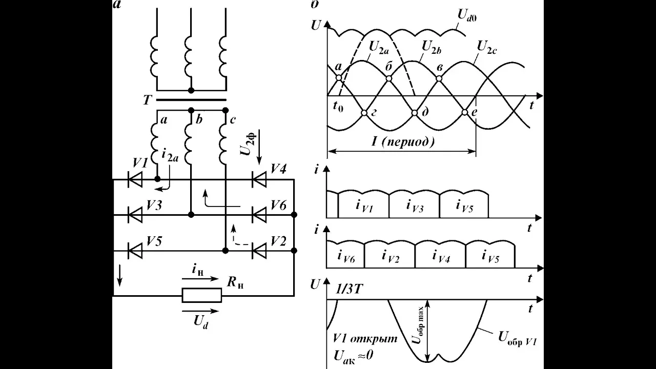
Трехфазные выпрямители
85.1K
Three-phase rectifiers convert three-phase AC voltage to DC using diode configurations; the single-pulse zero scheme uses two diodes producing three voltage pulses per cycle with noticeable voltage drops, while the six-pulse bridge scheme uses six diodes providing a smoother DC output with continuous current flow and minimal voltage ripple, making it more efficient for practical applications.
Click to watch →

Fonte Chaveada – Aula Completa para Iniciantes
107.2K
A switched-mode power supply (SMPS) converts AC mains voltage to stable DC output through a series of stages: input protection (fuse, varistor, thermistor, filter coil, capacitors), AC rectification using a bridge rectifier, high-voltage filtering with electrolytic capacitors, high-frequency switching via a MOSFET controlled by a PWM circuit (like CDK14), transformer-based voltage transformation with galvanic isolation, secondary rectification and filtering, and a feedback system using TL431 and optocoupler to maintain stable output voltage despite load changes.
Click to watch →

What is SMPS, Working Principle and Construction in Hindi.
154K
SMPS (Switch Mode Power Supply) is a critical component in modern industrial automation. It converts AC power to multiple DC voltage outputs (such as 6V, 12V, 18V, and 24V) required by computer-controlled machines. Unlike traditional power supplies, SMPS provides multiple voltage outputs from a single unit, simplifies maintenance, and enables easy component replacement. The evolution from simple push-button controlled machines to computer-controlled systems has made SMPS essential for powering various circuits within industrial equipment.
Click to watch →
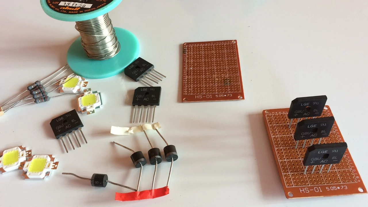
COMO FAZER UMA PONTE RETIFICADORA TRIFASICA
49.7K
A three-phase bridge rectifier requires three bridge rectifier modules (each containing two diodes, totaling six diodes) connected in parallel, where all positive terminals are joined together and all negative terminals are joined together, with the three-phase AC input connected to the middle sections of the bridges; this configuration converts three-phase AC power to DC power, suitable for applications like battery charging, though standard modules typically handle only 6-8 amps and require heat sinks for higher power applications.
Click to watch →

3 Simple Inventions with Car Alternator
794.6K
This extended demonstration covers integrating a custom three-phase rectifier with a car alternator and optimizing power output. The process includes: (1) Mounting the rectifier securely to the alternator body using screws and support boards, (2) Connecting three-phase wires from the alternator armature to rectifier inputs, (3) Applying excitation current to the rotor winding (12V, 5A laptop charger), (4) Connecting a 55W headlamp to verify power generation, (5) Demonstrating voltage regulator bypass effect showing 19.5V DC at 7.5A (146W power), (6) Achieving maximum measurable current of 9.54A producing 189W, (7) Using a 1.5HP DC motor to drive the alternator at high speeds, (8) Reaching 24-26V DC output when completely bypassing the voltage regulator. The demonstration proves that car alternators have inherent capability to produce much higher voltages than their regulated 12V design, limited only by mechanical stress and voltage regulator circuitry.
Click to watch →
AC to DC
Diode Solution
Forward Block
Single Diode
Four Diodes
Capacitor Boost
Rectifier Done
AC to DC
0:09- 1
Household power arrives as alternating current, constantly shifting direction.
- 2
Most electronics need direct current, flowing steadily in a single direction.
Active (Synchronous) Rectification
While traditional half-wave and full-wave rectifiers rely on passive diodes, they suffer from inherent efficiency losses due to the diode's forward voltage drop (typically 0.7V for silicon). In modern power electronics, Active Rectification (or synchronous rectification) serves as a critical alternative. This approach replaces passive semiconductor diodes with actively controlled switches, such as MOSFETs. By dynamically switching these transistors on and off in synchronization with the AC waveform, the voltage drop is drastically reduced. This minimizes power dissipation, reduces heat generation, and significantly increases overall energy efficiency, making it the preferred choice for low-voltage, high-current applications where standard passive rectifiers are too inefficient.
Understanding the fundamental differences between Alternating Current (AC) and Direct Current (DC), including frequency, polarity, and waveform cycle.
The operating principle of a semiconductor P-N junction diode, specifically its unidirectional current-carrying behavior under forward and reverse bias.
Basic AC circuit concepts, such as sinusoidal waveforms, peak voltage (Vp), and root-mean-square (RMS) voltage.
Fundamental electrical laws, such as Ohm's Law and Kirchhoff's Voltage Law (KVL), to trace current flow in simple loops.
Analyzing and implementing filter circuits (using capacitors or inductors) to minimize ripple voltage and smooth the pulsating DC output.
The study of DC voltage regulation, incorporating Zener diodes or linear regulators (e.g., 78xx series) to achieve a stable DC output despite load changes.
Calculating performance parameters of rectifiers, including rectification efficiency, ripple factor, and Transformer Utilization Factor (TUF).
Exploring advanced power conversion systems, such as Switched-Mode Power Supplies (SMPS) and three-phase rectification for industrial applications.
386.9K views6.3Klikes5:14@EugeneKhutoryanskyOriginal Release: 2015-08-24
The electric power that comes into our homes is in the form of AC voltage, which means that the voltage and current are constantly changing direction.
Most of our electronic, however, require DC voltage to operate, meaning that the devise requires a voltage and current that are always only in one direction.
Therefore, we need a way to convert AC voltage into DC voltage.
We can do this by using a device called a diode.
A diode allows current to flow in the forward direction, but blocks current trying to flow in the backward direction.
When current flows in the forward direction, both sides of the diode are at about the same voltage.
On the other hand, when the diode blocks current from flowing in the backward direction, the different sides of the diode can be at significantly different voltages.
Therefore, by adding just a single diode to the circuit, we have now ensured that the voltage and current across our device will always be only in one direction.
However, with this setup, the voltage and current across our device is zero half the time, and this is undesirable.
We can fix this problem by using a slightly more clever circuit which uses four diodes instead of just one.
Now, the voltage and current across our device are always in only one direction, and they are now no longer zero for half the time.
We can even further improve this circuit by adding a capacitor.
Capacitors have the ability to store charged particles.
When the capacitor is placed in this circuit, the capacitor stores and releases the charged particles so as to try to keep the voltage across the device constant.
We have now built an AC to DC converter, which we refer to as a rectifier.
Much more information about electric circuits is available in the other videos on this channel.
Up Next
33:58
Linear Power Supply Components Explained: A Full Build Guide
@electrarc240
641K views•2024-10-16

30:32
Ultrasonic Transducers: Resonant Frequency Measurement and Horn Design
@imajeenyus42
229.9K views•2017-02-22

54:16
Polymer Environmental Degradation: Mechanisms & Stabilization
@iit
1.8K views•2012-07-10

33:39
How a Student's Question Saved a NYC Skyscraper from Collapse
@veritasium
22.8M views•2025-04-26
Related Study Plans & Knowledge Roadmaps
Structured learning paths in Engineering
engineering
Building Acoustic Levitators: Physics & Arduino
01The Physics of Sound and Standing Waves
02Piezoelectric Transducers and H-Bridge Drivers
03Arduino Programming: Generating 40 kHz Signals
+ 2 more learning modules
14h5 modules
Explore Roadmap
engineering
Building Peltier Cloud Chambers: Particle Tracks
01Cosmic Rays & Cloud Chamber Physics
02Thermoelectric Cooling (TEC) Fundamentals
03Custom Liquid-Cooling Loop Design
+ 2 more learning modules
18h5 modules
Explore Roadmap
engineering
Yagi-Uda Antennas: Modeling, Build & VNA Test
01Introduction to RF and Antenna Fundamentals
02Yagi-Uda Antenna Design Principles
03Antenna Modeling and Simulation in 4NEC2
+ 2 more learning modules
18h5 modules
Explore Roadmap
engineering
ECG Monitor Design: Op-Amps, Filters & Noise
01Electronics & Breadboard Basics
02Op-Amps and Instrumentation Amplifiers
03Bioelectricity and ECG Fundamentals
+ 2 more learning modules
18h5 modules
Explore Roadmap