











![[EL02] Cours sur les dangers électriques/protections - Printemps 2021](https://i.ytimg.com/vi/tal1rYOtsUw/maxresdefault.jpg)


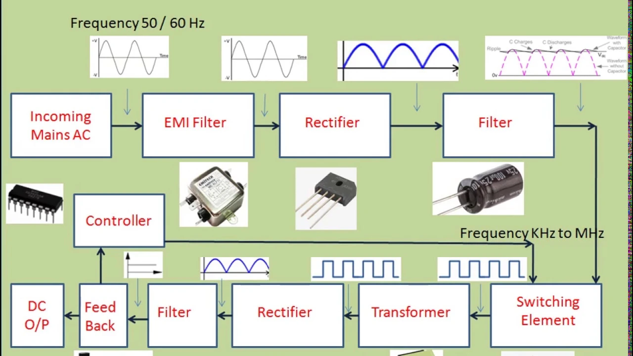








A linear power supply converts AC mains voltage to stable DC output through five key stages: (1) Mains input with fuse for safety protection, (2) Transformer for voltage reduction and electrical isolation, (3) Full-wave bridge rectifier to convert AC to pulsating DC, (4) Capacitor to smooth the DC output and reduce ripple, and (5) Closed-loop linear regulator using a Zener diode and op-amp feedback to maintain constant output voltage regardless of input variations or load changes.
Linear Power Supply Components Explained: A Full Build Guide
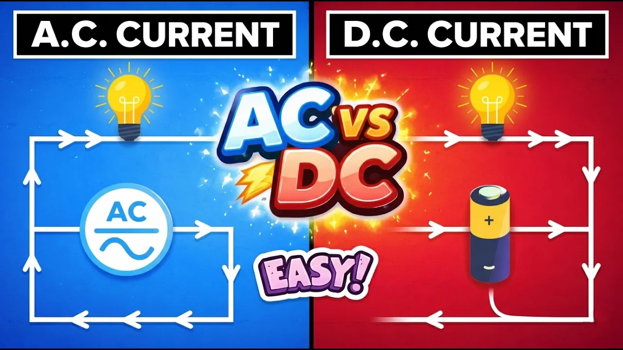
Added:Basic understanding of Alternating Current (AC) versus Direct Current (DC) electricity.
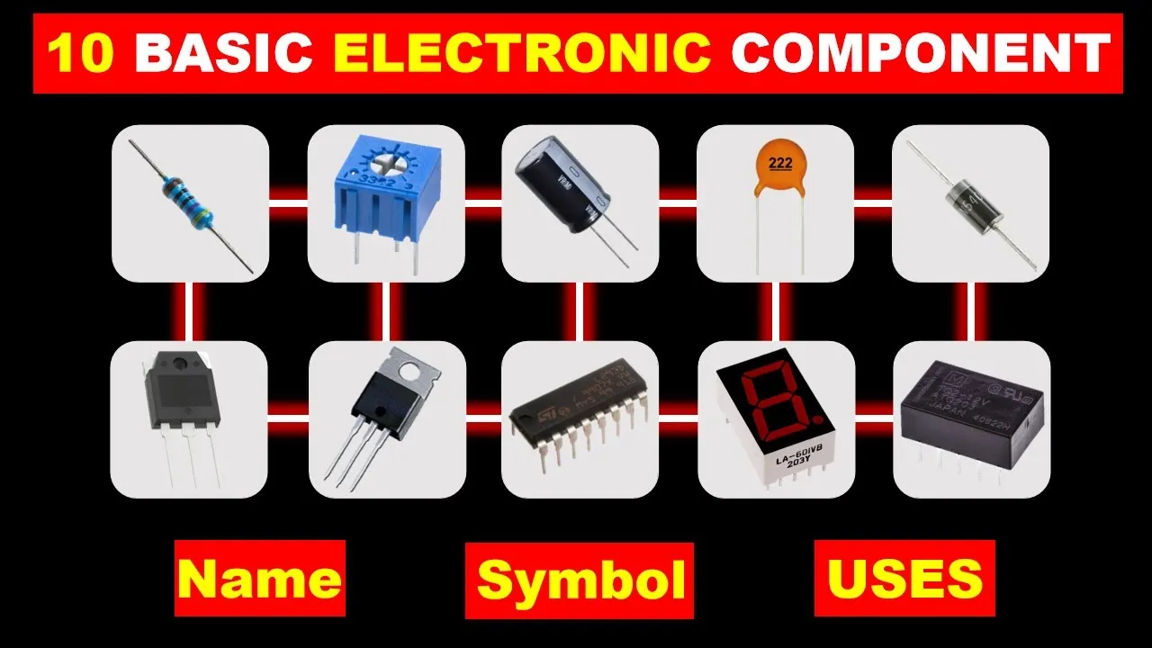
Fundamental operation of basic passive components, particularly diodes, capacitors, and resistors.
The concept of electromagnetic induction and how step-down transformers operate.
Essential electrical safety practices when working with high-voltage mains electricity.
Design and analysis of Switched-Mode Power Supplies (SMPS) for high-efficiency applications.
Thermal management principles, including power dissipation calculations and heatsink selection for linear regulators.
Advanced noise filtering techniques, ripple voltage calculation, and Low Dropout (LDO) regulator implementation.
Designing protection circuitry such as overcurrent, overvoltage (crowbar), and short-circuit protection.
641K views26.4Klikes33:58Original Release: 2024-10-16
now that we've taken a good look at switch mode power supplies it's only natural for us to now look at their predecessor linear power supplies now without a doubt the most obvious difference between these power supplies is the size not only is this switch mode power supply way smaller than this linear power supply it's also significantly more powerful at 50 wats versus 35 Watts but we don't really care how they look on the outside let's take a look at what's on the inside wow that's certainly old school nice and colorful with the wires but we can immediately see that the volume of the power supply is dominated by the size of this very large Transformer which is much much bigger than this tiny little Transformer on the switch mode power supply despite it carrying less power and the reason for that I've covered in my switch mode power supply video now I'm going to do this slightly differently to how I did my switch mode power supply video and that's because linear power supplies are so simple I thought instead of just pointing at the components and saying what they do why not build a power supply as we go and for that I've made this delightful collection of plug andplay components which consists of everything we need to build our own linear power supply these pcbs are from jlc PCB the sponsor of today's video jlc offer multi-layer pcbs in seven different colors which is ideal for multiboard projects like this one for example I have also made use of jlc pcb's excellent color offerings for my University's formula student car where the color of board provided a simple indication of the voltage of the circuits yellow for voltages between 600 and 15 50 volts purple for voltages between 150 and 24 and black for anything under 24 volts ordering from jlcpcb is as simple as drag and dropping your Gerber files selecting any of the many options you want for your board including the all important silk screen color and then proceeding to the checkout where you will be even further impressed by their extremely competitive pricing so when you next find yourself in need of lowcost high quality and maybe even colorful pcbs make sure to check out jlc PCB using the link in the video description right let's get started now the first thing we need is an input to our power supply and for that allow me to introduce the mains now the mains is very dangerous because it's high voltage and has the potential to Source very high current if you touch it the chances are you're going to die so please don't do this at home and as you can see the first component I've got is a fuse this is the very first thing our electricity is going to see when it enters our power supply and it's essentially a very thin piece of wire that heats up when current passes through it because of its resistance and if too much current passes through it'll break CU it gets so hot there is a difference between a fuse and just a piece of wire that being that a fuse is specifically designed to break at a certain current which is much better defined than just any old piece of wire also something that's very important for high voltage High current or DC is that fuses have specific features designed into them to ensure the flow of current is stopped effectively and safely one of the most prevalent examples of this is fuses containing sand with the idea being that when the wire inside it melts the sand will fall into the place of the wire to prevent any arcing and if there is any arcing and very high temperatures the sand will be melted and turned into glass which is an extremely good insulator this process of stopping the arcing is known as quenching and the fact that glass fuses like this one don't really contain any of those features is the reason why they should really be avoided to be honest but they do look nice and they make it very easy to tell if the fuse is blown or not as you can just use your eyes the next thing to add is a switch which will let us turn our power supply on and off there's not a great deal to cover on the switch except for explaining the reason why it must be on the primary side of the Transformer and not on the secondary side and I'll cover that once we've taken a look at the Transformer speaking of which here is the single largest heaviest and most expensive component of most linear power supplies the Transformer now actually explaining fully how a Transformer works is going to take a little bit of time so bear with me so a Transformer consists of a ferromagnetic core typically for Main's frequency this will be iron and for switch mode power supplies at higher frequency it'll be some form of ferite to make it a Transformer and not just a standard inductor you're typically going to have two or more windings in this case this is a simple Transformer with a primary and a secondary the primary is connected to the Main's input and the secondary is our output now to start things off we're going to ignore the secondary and just pretend that this is a regular old inductor the a C voltage that we apply to the primary winding is going to cause a current to flow not because of the resistance of the wire but because of the inductance of the Transformer now we have a nice equation for voltage across an inductor which is v = l * DT which basically tells us that the voltage across the inductor is equal to the inductance times the rate of the change of the current but we want current not voltage so with a small bit of mathematical fiddling we can see that the current is equal to the integral of the voltage divided by the inductance in other words the bigger our voltage the faster the current is going to increase so if we start by drawing out a nice sine wave that represents our AC Mains input then we can try and draw the current flow based on this drawing a line that is steepest where the voltage is highest and is flat where the voltage is zero as you can see we actually end up with the same shape as our voltage it's just shifted by 90° this is also known as a negative cosine function and those of you who are mathematically inclined will probably know that negative cosine is the integral of s now because this current flowing through the primary of our Transformer isn't in Phase with our voltage it means that despite measuring just over 30 milliamps of AC current flowing into our power supply the actual real power being consumed is very little if we simply multiply the 31 milliamps of current draw by my 247 Vols AC Supply we're looking at something in the region of 7 and 1/2 Watts which as we have no output connected would have to be dissipated inside our transforma but I can tell you now this is not warm enough for 7 and 1/2 Watts it's only slightly above ambient to be honest and this is because almost all of that 7 and 1/2 Watts we've calculated is actually what's known as reactive power and what we've just calculated by multiplying the current by the voltage is the apparent power which is where you just get the RMS voltage and the RMS current and multiply them together but voltage time current is power why isn't it power well if we look back at the waveform we drew earlier and go through the waveform and draw out the power so that's the voltage waveform multiplied by the current waveform we can see that the average power is actually zero so even though we've got current flowing through our Transformer it's not actually consuming any power and this reactive power is the reason why our power switch must be before the Transformer cuz if we put the switch after the Transformer although the real power consumed is going to be very small the apparent power is quite significant an apparent power is what dictates the sizing for all components in the National Grid if you look at any Transformer the power it can handle won't be real power in Watts it'll be apparent power in VA as you can see on this Transformer we're using which is rated for 12 VA or volt amps and this is just simply because cable and the thickness of windings in Transformers are dictated by the current not the power so even though this current isn't actually doing anything it's just going in and out of the loads we still have to size all of our cables and switch gear and other stuff for this apparent power now let's return to our Transformer and it's almost time to have a look at our secondary winding but just before that we need to understand how energy is going to transfer between the two windings and this happens through magnetic coupling that current that we've just measured that's flowing through our primary winding is going to produce a magnetic field inside the coil which is concentrated by our ferromagnetic core to stop most of it from just leaking out into the environment now as you can clearly see our secondary winding is also wrapped around this ferromagnetic core and an interesting thing happens if you have a conductor like this inside a changing magnetic field what we get is a voltage induced equal to n * D DT where n is the number of turns we have and DT is the rate of change of the magnetic flux now the magnetic field that we have inside the core is proportional to the current on the primary so if we have a look at the waveform that we've drawn for the current on the primary how do we get the voltage coming out from that well the voltage is proportional to DDT the rate of change of the current or the derivative of the current now we've already seen that this current is proportional to the integral of the voltage coming in and the voltage coming out is proportional to the derivative of that current now this is really nice because differentiation is the opposite of integration so to skip some maths the output waveform is exactly the same as the input waveform because we integrate the input and then we differentiate that so we now kind of know how the Transformer works we put a voltage into the primary which makes a magnetic field which induces a voltage into our secondary but wait a minute voltage in voltage out what's the point well there's two main reasons to use a Transformer first of which is that we've achieved electrical isolation there is a physical Gap between the primary winding and the secondary winding no electrical connection whatsoever and for safety reasons this is an absolute necessity for anything that a human might come into contact with and the second reason to use a Transformer is because of the transformation that it can perform we can use a Transformer to scale the input voltage at the output and this is simply a function of the number of turns of the primary and secondary windings that's because the magnetic flux that we put into our core is proportional to the primary voltage divid dived by the number of turns and the voltage at the secondary is proportional to that flux multiplied by the number of turns so essentially what this means is if we have the same number of turns on the primary and secondary we get the same voltage out as we have coming in if we have twice as many turns we get twice the voltage on the output or in the case of this Transformer we've got about 20 times fewer turns than we have on the primary which means our 240 is volts coming in comes out at a little bit over over 12 Vols now the last thing to cover with our Transformer is what happens when we connect your load so when we draw current from our secondary winding well just like on the primary any current that flows through the secondary winding is going to produce a magnetic field however unlike on the primary winding this current that we've put on the secondary winding assuming a resistive load is going to be in Phase with the voltage and just like how the voltage applied to the primary produced a voltage on the secondary the current that we draw from the secondary will draw some current from the primary according to the inverse of the turns ratio so if we have 20 times less voltage on the secondary than the primary that means we have 20 times less current on the primary than we have on the secondary so the overall power on the input and output remains pretty much the same now to finish off with the Transformer we're going to take a look at the voltage and current waveforms on the oscilloscope so first of all here's the voltage waveform as you can see it's fairly sinusoidal it's not a perfect sign and that's because I'm looking look at the output on the secondary and not the primary that's because if I connect my oscilloscope directly to the mains it'll blow up and I don't have a high voltage differential probe yet but something quite nice that I do have is a high bandwidth hall effect probe which is used for measuring current it's just like the clamp meter I used earlier except it has a BNC output that can be connected to an oscilloscope so let's now have a look at the current waveform oh uh as you can see it's not sinusoidal and it doesn't really look anything like what we expected except for the phase relationship which you can see is indeed the same 90° shift as that cosine that we expected now the reason for these ugly spikes in the current is that the magnetic core of the Transformer has a limit to how much magnetic flux it can hold before it goes into something called saturation which results in the inductance dropping massively and if you remember back to when we were calculating the primary current that was equal to the integral of the voltage which is the area under this yellow curve divided by the inductance so if I zoom in a little bit this is the zero crossing point so the integral of the voltage or the area under this curve we're going to start counting from here so we've got more and more and more and more and more flux as we progress along because the area under the curve is increasing at this point our flux reaches the limit that the core can handle and the core starts to saturate but the voltage is still positive so we're still trying to pump in more flux but the core can't handle any more flux so the inductance drops which means we're dividing by a smaller number which means our current starts to rise dramatically now it's not unusual to have a little bit of saturation in Main's frequency Transformers just to squeeze out as much performance as possible from a certain size I suspect this is a little more than this Transformer was designed for because technically it's rated for 230 volts and my Main's voltage today is 247 volts which obviously means that the area underneath this voltage curve is going to be a decent amount More Than This Transformer was designed for so you might find that at 230 volts this blue waveform is a little bit nicer and you can see here I've added a measurement for the RMS current and it's says 33 milliamps which is about the same as what we got from our clamp meter that we put on earlier although can also see that the maximum or Peak current is almost 80 milliamps because of this saturation and just before we move on to take a look at rectification I just wanted to quickly show that for some loads a Transformer is all you need here we have a 12vt lamp it's actually a car headlight bulb and you can see I can plug it in and it'll happily run on the ac voltage that we have coming out of our Transformer this isn't the case for many loads but it is worth considering because sometimes it's easiest to just keep things simple and a basic load like a filament lamp or a heater doesn't care about whether it's being supplied with AC or DC that's in contrast to a load like a motor which does care quite a lot about the polarity of the supply as you can see when I plug in this motor it just vibrates oh cranky and that's because the direction that the motor spins is determined by the polarity of the supply so if the voltage we're putting in is switching Direction 100 times second which is what the output of the Transformer is doing our motor is going to try and do that too so clearly there is a need for us to convert our AC coming out of the transformer into DC and the way to do that is with a diode a diode is essentially an electrical oneway valve so it allows current to flow in One Direction but blocks it in the other so by using the diode we're essentially removing the negative half of our AC wave so let's take a look at that on the scope here we can see the wave form of the output voltage from the Transformer that we looked at previously but if I move the position of my probe to the output of our diode we can see clearly we're now only getting the positive half of that waveform with the negative half that should be coming down here deleted from existence and actually looking at that number there the RMS reveals one of the main problems with using a single diode for rectification and that's that the average voltage ends up being quite low because we're at 0 Volts for half of the time and that means that when we connect up the motor to the single diode rectifier it's not going to spin as fast as we'd like it to and another problem with the single diode rectifier is that we end up with asymmetric loading of the Transformer and the mains and to demonstrate that I'm going to have to replace this very light load with a bit of a heavier load so you can see here I have this big high power resistor I'm going to connect that to the output of our rectifier and now if we take a look at the current waveform and I'll get rid of the voltage to make it a bit clearer you can see how asymmetric this is if I remove the load we get that current waveform that we saw before where despite it being ugly the top and bottom sides are the same but now when I connect the load on the output of our diode we have a lot more negative current than we do positive current and to show that that's caused by the diode I'm now going to flip the diode around and as you can see our waveform has also flipped not good and the way that we get around these issues is to swap our single diode for a full Bridge rectifier which is a special configuration of four diodes which essentially grabs the negative half of our input wave and flips it around so that all we get is positivity it's wonderful and I can show that on the scope there we go oh there we go you can see how we now no longer have the Zer volt section we have nothing but pure positivity and our RMS has indeed increased from about 11 Vol to about 14 Vols and as you can hear when we connect the motor up it's also spinning faster because it now has a higher average Supply voltage we can now also take another look at the input current which as you can see when I connect the load no longer becomes all weird and asymmetric it changes equally in positive and negative Cycles which means we have much better utilization of our Transformer we're not just passing current through it half of the time brilliant the full Bridge rectifier is the perfect solution then well I'm afraid there is just one slight downside to this wonderful arrangement of diodes and that's because when current passes through a diode there's a voltage drop called the forward voltage which is fairly constant irrespective of the current that's flowing through the diode and this is normally about 0.6 volts so when we have our single diode rectifier obviously we get nothing coming out of the negative half of our AC wave but the positive half is reduced by 6 Vols bummer but now if we consider the full Bridge configuration there's four diodes in here and for either positive or negative half of the wave we're using two of them so now we've got double 1.2 volt drop which means that the losses inside the rectifier are going to be quite a bit higher and that means that a single diod rectifier is more efficient than a full Bridge rectifier and a single diod rectifier is quite commonly used in very low power appliances especially those without isolation because then they have no Transformer so there's not so much concern about underutilizing and wasting your transformer for this reason some power supplies and some Modern DC todc converter topologies use a special Transformer winding configuration called the split secondary which allows a different type of rectifier to be used the linear power supply that we looked at briefly earlier actually has such a configuration as you can see here the secondary side of our Transformer has a black wire and two purple wires so the way to think of this winding is that you've got zero volts on the black wire and then a positive and negative AC output and then each one of these is fed through a single diode rectifier so when this one's positive this lower diode is conducting and we've got a 6V drop then when it goes negative the voltage across the other winding is positive so our current instead flows through this diode and we have a 0.6v drop this means we still have full wave rectification on the output but we've only got two diodes instead of four which means less voltage drop and really it's quite a smart idea so we now have an isolated DC output from our power supply are We Done Yet no and that's because many loads need a smooth DC output which our rectifier alone doesn't provide and to demonstrate this I have the load of a speaker this speaker is connected through a DC blocking capacitor so this represents an audio amplifier but with no audio playing so imagine you're listening to a song on Spotify you've just pressed pause you expect silence don't you well if I add this resistor into the circuit this represents a bit of current drawer inside the amplifier Ah that's not great and that comes from the Ripple that we've seen despite the fact that our voltage is now only POS positive it still goes up and down and up and down and up and down and to stop it from doing that we're going to add a capacitor so the timer has now come to once again have a look at our output waveform on the oscilloscope and let's quickly remind ourselves of what the output voltage from the rectifier looks like without any capacitor as we can see we have that recognizable humped DC and this waveform is exactly what we could just hear coming out of the speaker not great let's see what happens now if we add in a capacitor ah that looks much better as we can see there's still a little bit of Ripple but overall our DC is much smoother and you can see the RMS has gone up massively we're now at 20 volts RMS because we're pretty much holding the peak voltage continuously the only reason it drops a bit is because after the peak of the output of the rectifier the capacitor has to supply all the energy to our load until the next Peak comes to charge it back up which means the load will discharge our capacitor slightly and we can see that by swapping to a stronger load so here I have the daddy load three big blue resistors in parallel and look at that Ripple now the capacitor is really struggling to hold the voltage up and our Ripple is quite significant our RMS has dropped from 20 volts down to just 15 volts and I don't think our speaker would really be getting much benefit from adding this capacitor so what do we do now we need a smooth output we've got our load we can't do anything about that well the amplitude of this Ripple so how much the capacitor's voltage drops between each half cycle that charges it back up is inversely proportional to its capacitance if we put in a bigger capacitor the voltage will drop less so let's try swapping our 180 microfarad capacitor for this 5,600 microfarad capacitor boom look at that that voltage is as smooth as my RZ and it's exactly what we need for our amplifier application so now that we've seemingly solved our problem let's try reconnecting the speaker and see if the noise has gone away sounds good to me there's a tiny little bit of buzzing still and that's because speakers are very fussy you can give them a few molts of Ripple and you might be able to hear it and that's why audio amps have massive capacitors relative to the amount of power that's going through them now nothing's perfect and there is one major downside to adding a big smoothing capacitor and that comes in the form of power factor or more specifically quality factor and this is essentially how sinusoidal our current draw is now because of the saturation in our Transformer even with no load the current draw of our power supply is pretty poor I think you'd be hard press to say that this is a sinos soidal waveform but watch what happens when I add a big resistive load to the output of our power supply we end up with a new even bigger Spike and this is caused by the big rush of current that's needed to charge the capacitor back up for every half cycle to fill in all that energy that the capacitors had to supply to the load while the voltage has been lower and these current Peaks manifest themselves on the input current to the power supply which gives us this very ugly waveform this problem can be completely fixed with something called active power factor correction which is something I'm going to cover in an upcoming video but power factor correction gets into the realm of modern Power Electronics and the complexity would be a completely pointless add add to a linear power supply you might as well just go switch mode at that point and most high power switch mode power supplies do in fact have active power factor correction thumbs up for regulations now just like a young Electro in the back of the car on the way to the Lake District I can hear you all shouting are we there yet not quite I'm afraid we have one more problem to solve with our power supply and that's that many loads require a specific voltage and that voltage needs to be stable irrespective of ch es in Main's voltage or load and at the moment our output voltage is affected by both of those as you can see with no load connected we have a beautiful perfect 22 volts but if I connect a small load to our output that 22 volts drops down to 21 volts and if I bring back Daddy load from earlier oh 14.6 Vols that is shocking and shall not be tolerated what we need to keep our output voltage constant is is some form of regulator there's a few ways that a regulator can work and I've made two different ones to show the two most common types that being open loop and closed loop and these are very similar but we're going to start by looking at the open loop because it's not as good and that's the order that things are always done now the job of a linear regulator like this is very simple it has a Target voltage to achieve on the output so let's say 12 vs and it needs to introduce a voltage drop that brings the input down to 12 volts no matter what the input is or how much current is being drawn so for example as we could see before when we have no load our capacitor is charged to 22 volts so our regulator would need to drop 10 volts to get 12 out whereas when we put daddy load on our capacitor voltage drops down to just 15 volts meaning our regulator only has to drop 3 volts but how do we Implement such a circuit well at the heart of almost all Regulators is something called a Zena diode so let's take a look at that so here I have a Zena diode as you can see it looks just like a normal diode and sometimes it's quite hard to tell the difference until that is you apply a voltage to them and that's because Zena diodes conduct electricity in both directions what's the point of that it's just it's just a wire well in One Direction they're just a standard diode with our 0.6 volt drop which we'll be able to see if we apply some current through it 0.6 0.7 close enough but where Zena diodes make their Mark is when you flip them around now if we turn on the power supply we can see we're getting a voltage drop of about 6 volts that's a lot more than the 0.6 we had before and the voltage drop that you get across a Zena diode when it's reverse biased can actually be handpicked if you go online and shop for zena diodes you can buy 3.3 volt ones 3.6 volt ones 12 volt ones you can get whatever you like but what's really special about this reverse voltage drop is that it changes very little with current as you can see we currently have a very small amount of current flowing through less than 10 milliamps but if I increase this current the voltage drop barely changes 6.1 6.2 now let's take a look at this open loop regulator circuit because it's incredibly simple here's our input here's our output the negative connection passes straight through this is our Zena diode and this is a series resistor the positive connection of our input voltage is here and the shared negative is here these two pins are joined together just like this schematic shows what this means is that a current is always going to flow in this direction from the positive input down to the negative and as we've just seen a current passing through a Zena diode is going to result in a fixed voltage drop so even if our input voltage changes which would mean the current changes the voltage across the zena is going to stay almost exactly the same so can we just connect our output to here no because then our output would be connected through this resistor which would result in a voltage drop when a heavy load is connected so what we have to do is we have to buffer this nice voltage to get a voltage at the output that's the same but stronger so the load can't pull the voltage down and that is what this final component is for this is a bipolar Junction transistor or BJT and by connecting the reference to the base of the transistor we form what's called a voltage follower which does exactly what we need the only slight downside is that this transistor is a bit like a diode it introduces a 0.6 volt drop so that means our reference voltage needs to be set 0.6 volts higher than what we want at the output so let's connect this to the circuit and see what happens as you can see with no load we're looking at about 13 volts and if I connect to the weakest of my loads drops a little bit and firstly that's because this 0.6 volt drop in the transistor is a bit like a diode drop it increases as more current passes through so we're going to be getting more voltage drop at higher currents inside our transistor and then also the more current that we draw the more current the transistor is going to draw through its base which is current coming out of our voltage reference which means that eventually our reference voltage is also going to get pulled down and to prevent that we use the lowest possible value of series resistor here which makes the open loop regulator quite inefficient because even with no load connected there's a not insignificant amount amount of current being drawn by the reference circuit and we can also see now the effect of things heating up our voltage is increasing it's now 12.8 so let's swap load now and let's try The Next Step Up 12.8 again that's not too bad with our next load we drop down to 12.75 still pretty good and finally with Daddy load we Dro down to 12.6 and again as things are heating up we can now see the voltage is dropping the reason the voltage was increasing before is that the reference circuit was heating up whereas now our transistor is the one heating up and as that heats up the voltage drop gets bigger but all in all the open loop regulator seems to work quite well but what about the closed loop regulator what's the difference well the closed loop regulator is almost identical to the open loop regulator it has the same Zena diode with series resistor and exactly the same voltage follower transistor the difference is that we've now added an opamp and a potentiometer that controls the feedback and that's why it's called closed loop because our circuit is now looking at the output voltage and making adjustments to compensate for any changes in the voltage drop in the transistor the current draw from the reference circuit is also much lower because it's now connected just to the input of an opamp and that means we can use a much higher value of resistor in the reference circuit and eliminate that wasted power that we had with the open loop circuit so let's plug the closed loop regulator in and see how it performs the first thing I'm going to do is show off the fact that we now have an adjustable output voltage by fiddling with this trimmer I can turn the output voltage up or down to my heart's content but I'm going to set it around what we had before something between 12 and 13 volts there we go about 12.4 now let's once again go through the various loads and see how this voltage changes wow with the weak load nothing we're still at 12.44 it makes no difference now let's try the next load 12.44 next load 12.45 I'd ignore those tiny variations they might even just be variations in my Main's voltage from my neighbor turning the kettle on and finally daddy load wow that's the power of a closed loop regulator and that's the reason why almost every Power Supply not just linear but switch mode as well is going to be using closed loop regulation because closing the loop by adding feedback essentially gives you the perfect circuit it doesn't matter how big your voltage drop is and how nonlinear the components are a simple feedback circuit can compensate for it all and there we have it ladies and gentlemen the complete linear power supply we've gone over the Main's input coming in the fuse to protect our circuit the switch to turn our circuit on and off the Transformer to take our high voltage to low voltage and provide us with isolation our rectifier to go from AC to DC our capacitor to smooth that DC out and our regulator to give us a fixed output voltage now all that is left to do is to connect up our load turn on our power supply and say thanks for watching goodbye [Music] [Music]
Up Next

10:50
Choosing Rectifier & Capacitor for AC-DC Conversion
@Schematix
238.4K views•2017-09-04

30:32
Ultrasonic Transducers: Resonant Frequency Measurement and Horn Design
@imajeenyus42
229.9K views•2017-02-22
16:49
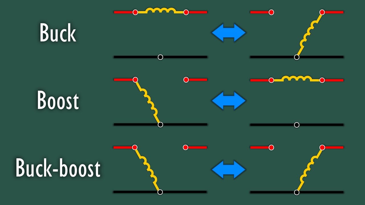
Buck, Boost, and Buck-Boost Converters Explained
@electrarc240
236.9K views•2024-11-18

33:39
How a Student's Question Saved a NYC Skyscraper from Collapse
@veritasium
22.8M views•2025-04-26
Related Study Plans & Knowledge Roadmaps
Structured learning paths in Engineering
engineering
Building Acoustic Levitators: Physics & Arduino
01The Physics of Sound and Standing Waves
02Piezoelectric Transducers and H-Bridge Drivers
03Arduino Programming: Generating 40 kHz Signals
+ 2 more learning modules
14h5 modules
Explore Roadmap
engineering
Building Peltier Cloud Chambers: Particle Tracks
01Cosmic Rays & Cloud Chamber Physics
02Thermoelectric Cooling (TEC) Fundamentals
03Custom Liquid-Cooling Loop Design
+ 2 more learning modules
18h5 modules
Explore Roadmap
engineering
Yagi-Uda Antennas: Modeling, Build & VNA Test
01Introduction to RF and Antenna Fundamentals
02Yagi-Uda Antenna Design Principles
03Antenna Modeling and Simulation in 4NEC2
+ 2 more learning modules
18h5 modules
Explore Roadmap
engineering
ECG Monitor Design: Op-Amps, Filters & Noise
01Electronics & Breadboard Basics
02Op-Amps and Instrumentation Amplifiers
03Bioelectricity and ECG Fundamentals
+ 2 more learning modules
18h5 modules
Explore Roadmap