














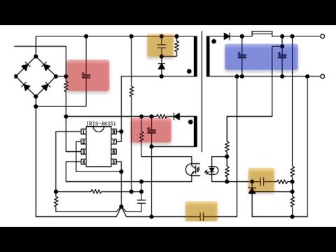

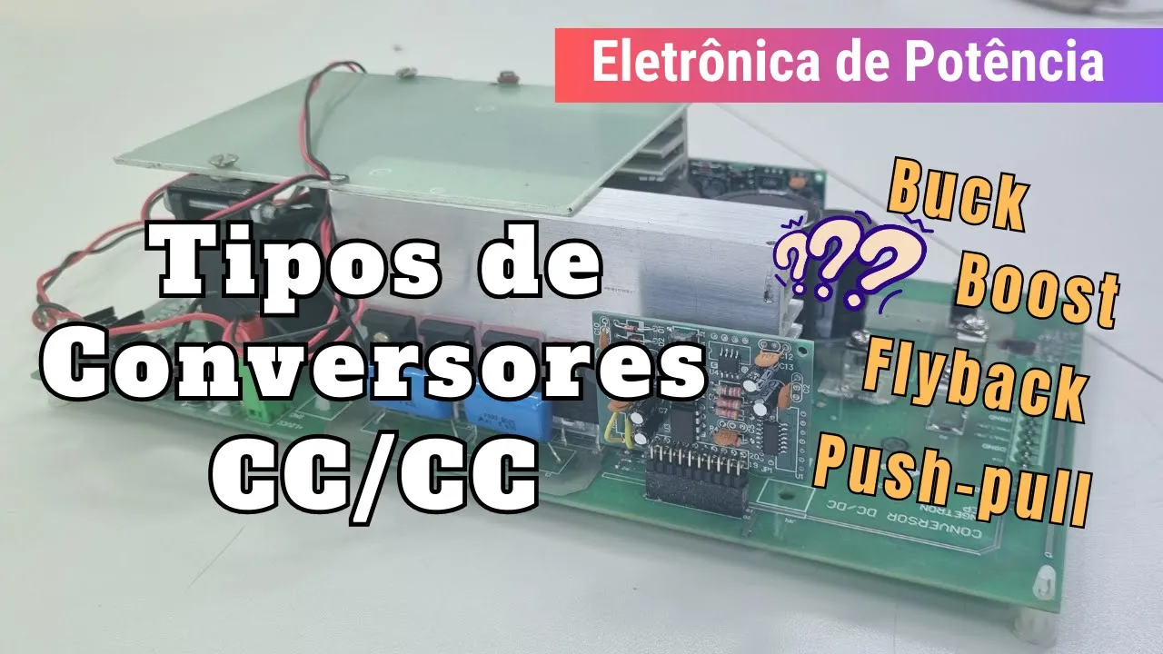




![[#4 EMC webinar] 10 błędów w projektach elektroniki pod kątem EMC #AkademiaEMConline](https://i.ytimg.com/vi/MBwwD3BkI_M/maxresdefault.jpg)
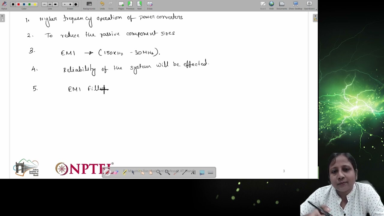
![EMI filter design [Technical Webinar]](https://i.ytimg.com/vi_webp/w_UBNx12_n4/maxresdefault.webp)

DC-DC converters use switching technology to efficiently convert DC voltage levels by storing energy in an inductor and transferring it between input and output through three fundamental topologies: the buck converter (which steps down voltage by connecting the inductor to the output during switching), the boost converter (which steps up voltage by connecting the inductor to the input during switching), and the buck-boost converter (which can both step up and step down voltage but inverts the polarity); these topologies differ in how they connect the inductor's fixed terminal and whether they use MOSFETs or diodes for switching, with continuous current flow enabling simpler designs and higher power density.
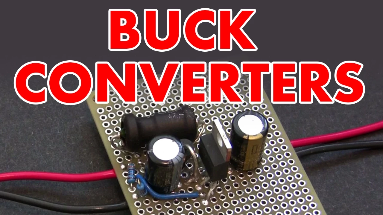
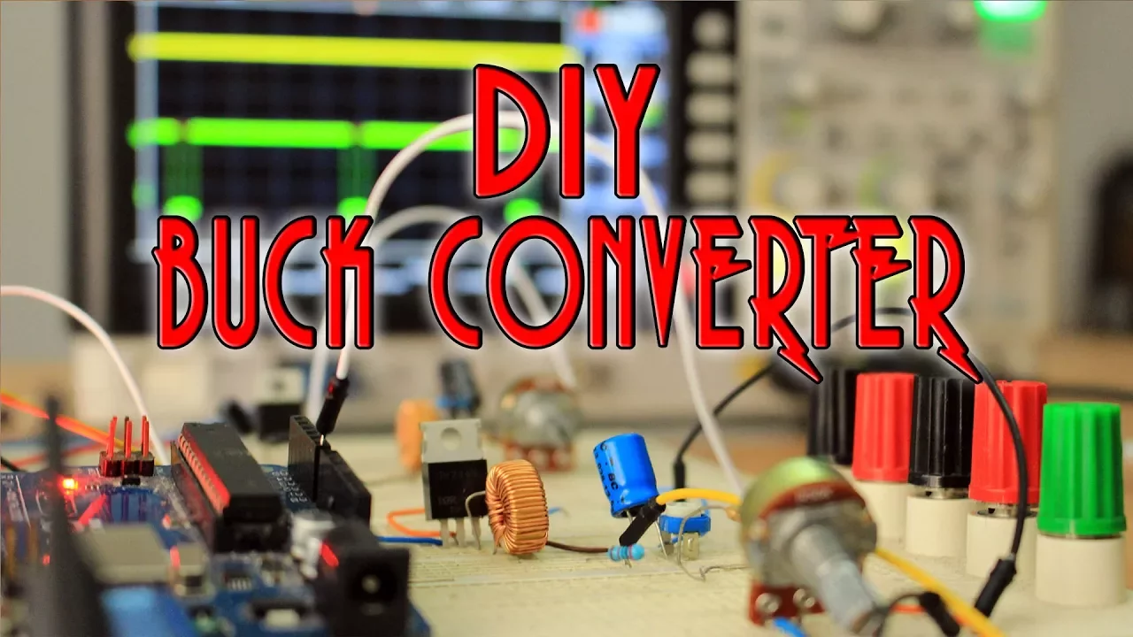
Buck, Boost, and Buck-Boost Converters Explained
Added:Basic DC circuit analysis including Kirchhoff's Voltage Law (KVL) and Kirchhoff's Current Law (KCL).
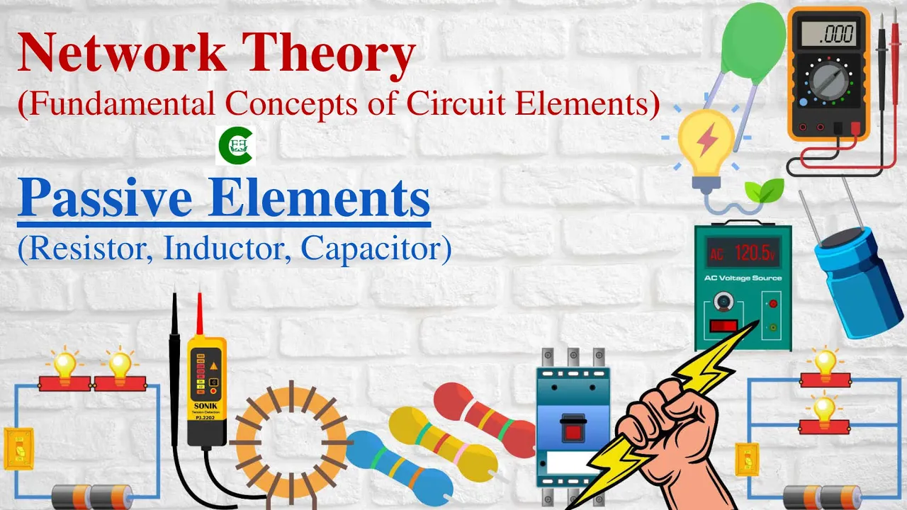
The transient behavior and energy-storage characteristics of passive components, specifically inductors and capacitors.
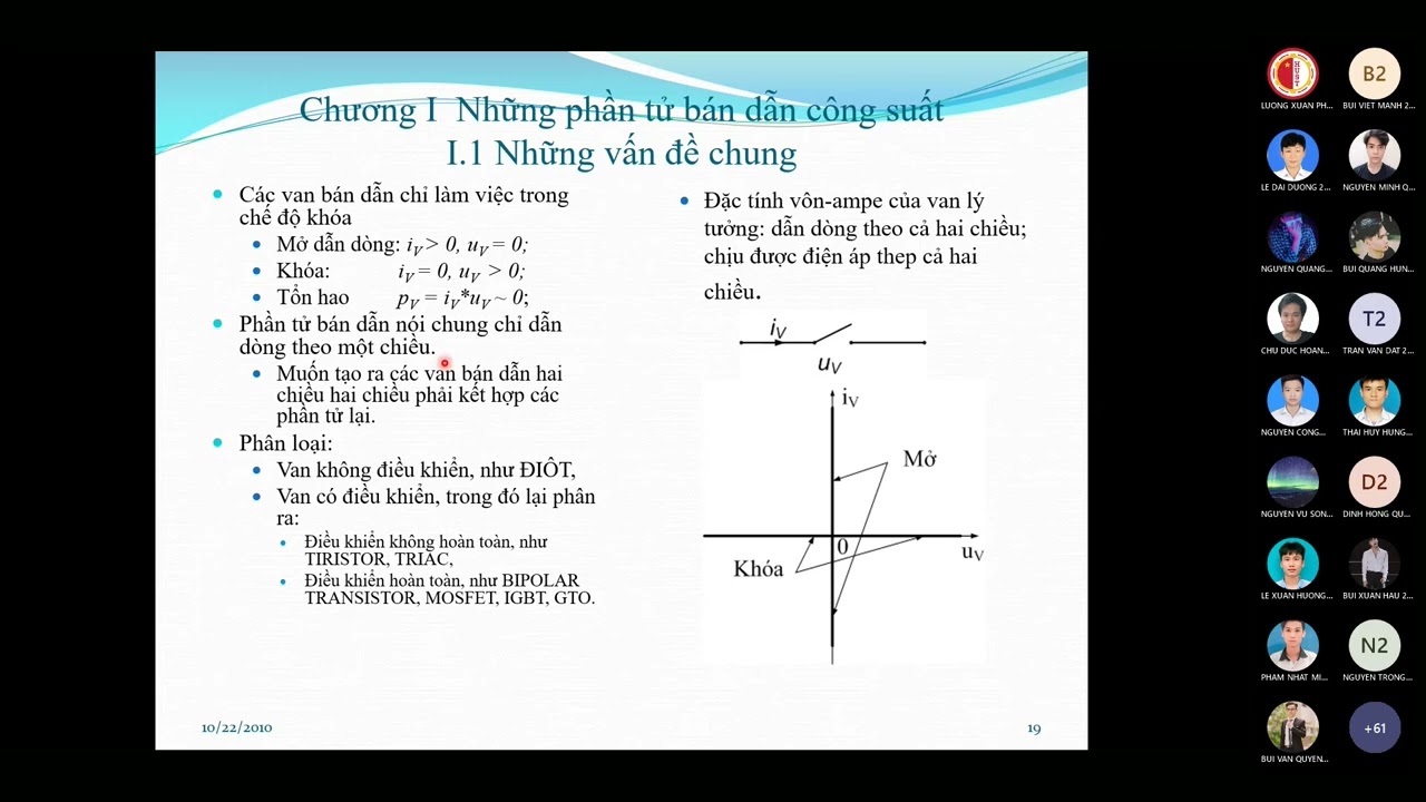
The fundamentals of semiconductor switches, including the operational principles of diodes and MOSFETs in switching states.
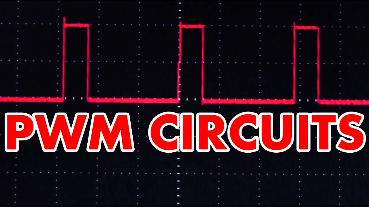
The concept of Pulse Width Modulation (PWM) and how duty cycle controls average voltage.
Closed-loop control systems (such as PID control) and feedback mechanisms for maintaining stable output voltage under varying load conditions.
Analysis of parasitic losses, power efficiency calculations, and thermal management strategies in switched-mode power supplies (SMPS).
Advanced converter topologies, including isolated DC-DC converters like Flyback, Forward, and Push-Pull converters.
Electromagnetic Interference (EMI) challenges and the design of input/output filters to comply with electromagnetic compatibility standards.
236.9K views10Klikes16:49Original Release: 2024-11-18
a par electronic converter takes one form of electrical supply and converts it to a different one for example a rectifier takes AC to DC an inverter takes DC to AC and a DC to DC converter does exactly what its name suggests whilst changing the voltage and sometimes providing isolation too today we're going to be taking a look at the latter DC todc converters in the old days if you had a DC Supply say from a battery and you wanted to increase or decrease the voltage in a somewhat efficient manner you'd likely be looking at using one of these a rotary Transformer these are essentially multiple DC motors mechanically joined together so powering one spin is a shared shaft that spins any others which act as generators wound to produce whatever voltage is required there are many problems with these such as mechanical wear and significant losses which is why we moved on to using switching converters as soon as clever scientists were able to make us reliable semiconductor switching devices the fundamental idea of modern switching power Electronics is that in an ideal switch there is no current flow when it is open and no voltage drop when it's closed as power is voltage times current this means that there is never any loss in the switch because we don't have both at once excellent this is in contrast to older linear converters that for the example of reducing a voltage essentially just add a controlled resistance in series with the load to introduce the required voltage drop that's voltage and current together so there is significant power loss hence why we have moved on from such circuits in most applications by simply controlling how much time we have the switch open and en closed we can control the output voltage of our converter there are many ways this can be implemented but the most common by far is to adjust the ratio between time spent on and off whilst keeping the overall time the period constant this is known as pulsewidth modulation or pwm now if this video inspires you to make your own dcdc converter and hopefully it does make sure to head over to jlcpcb with prices for two layer boards starting at less than 2 quid you'll definitely have plenty of cash left over for some nice components I got quite a few boards made for this series of videos on DC todc converters and they all look marvelous especially with the enig goldplated Finish which I highly recommend if not for the superior quality than at the very least for the bling factor to get your boards from jlcpcb all you need to do is drag and drop your Gerber files onto their website select any options you need hopefully a bit of bling and then select your shipping option from a great range of speed and affordability and now back to DC todc converters efficient power conversion requires storage of energy this is because the onoff nature of the switching needs to be smoothed out before we send the power to our load there are two components we can use for this capacitors and inductors capacitors are used to smooth voltage they'll do whatever they can to maintain the voltage across them this means they'll Source a very high current if you try to discharge them quickly and also sink a very high current if you try to charge them up quickly we can use this to produce brief High current Pulses from a constant lower current input for example in a buck converter in contrast inductors are used to smooth currents again they'll do whatever they can to maintain the current going through them they're this time using voltage rather than current as their weapon of choice this means if you try to quickly change the current flowing through an inductor it'll counter with a voltage and can produce dangerously high voltages if disconnected while current is Flowing as with the capacitor we can use this effect to our advantage this time to produce brief high voltage Pulses from a low voltage input flyback converters using special high voltage coupled inductors like this one use this effect as you can see inductors and capacitors are perfectly opposite components so if you understand one you understand both just swap voltage for current short circuit for open and electric fields for magnetic fields the converters we're looking at today are like all my ST power converters supplied by a voltage source this means our primary energy storage element the one that switches between input and output needs to be an inductor this is because as we've seen we can't just connect a capacitor across a voltage source without big current flow which would bring significant losses and likely break other components in the converter we can however connect an inductor directly across a voltage source as I'm now going to demonstrate using this massive inductor the reason for using such a big inductor is that essentially we can slow down time the bigger the inductance the slower all of the effects we're looking at are going to happen so it'll make them a bit easier to see now here we have the oscilloscope showing current through our inductor which at the moment is at zero and what I'm going to do now is connect a voltage source across the inductor and there you can see a nice G Dental ramp as the current slowly increases the rate of which is limited by our inductance so connecting an inductor across a voltage source lets us carefully decide how much energy we want to put in we can either leave it connected for quite a while and fill it up completely with energy or we can disconnect it partway through the ramp like this so that we can control how much energy we've put into the inductor really cool so now that we know we need an inductor let's have a think about how we can connect it in our circuit we have a DC input and a DC output and as these converters are not isolated I'm going to join the negative connections of the two together so now we can clearly see that there are three possible points or nodes to which the two terminals of our inductor could be connected in order to convert energy we must move our inductor between two of these possible locations with the first being to put energy in and the second to release that energy this means there are three possible pairs of locations for our inductor and judging by this video's title there's also three fundamental converter topologies coincidence I think not we're going to start by looking at the weirdest of the three as once we understand that the other tool will seem relatively simple when we keep one terminal of the inductor on the negative rail at all times and switch the other between input and output we end up with a buck boost converter now in our simple diagram here we have positive above negative for our input so that means that while the inductor is connected in the first step it's getting charged up with a current that's increasing like shown earlier and this current is going to be flowing down from top to bottom the main reason why I call buck boost weird becomes apparent when we take a look at our output when we pivot over our inductor the current is going to continue flowing in the same direction but as the inductor is now acting as our source providing energy to the output it's going to be pulling charge in through the top terminal and out through its bottom because it's pushing charge out of its bottom that's actually going to be the positive terminal of our output which essentially just means our output voltage will be negative in relation to the input this really limits applications for the standard buck boost converter as most systems want all voltage rails to be positive with respect to a common negative which is not the case here while outside the scope of this video I'd like to quickly mention that the isolated buck boost converter known as the flyback is almost certainly the most commonly used isolated topology because they're extremely simple and once isolated don't suffer from the inverted output problem because you can simply flip the windings around I've gone into more detail on flyback converters in my switch mode power supply video linked above next I think we should take a look at Boost converters because the first of the two steps is the same as the buck boost we place our inductor across the supply to charge it up the difference comes when we want to take the energy back out of our inductor as now instead of our fixed point being on the negative rail we're going to fix the inductor at the positive input this means during the second step we not only get the energy from the inductor at the output but this is added to energy coming from the input to boost it hence the name boost converter this means a boost converter is output voltage cannot be less than the input as we're always adding to the supply voltage a nice effect of this boosting action is that unlike the buck boost converter we don't need to store all the energy that passes through the converter in our inductor only the additional energy required for the boosting sadly there's no such thing as an isolated boost converter because the Boost converter adds to the input and on the secondary side of any isolation there won't be an input to add to finally we have the buck converter which places the fixed terminal of the inductor on the output in the first step the inductor is charged up by the difference in voltage between input and output this means the input voltage must be larger than the output or current will try to flow in the wrong direction once the inductor is charged up we pivot it so that it stored energy is passed onto the output now there's a fairly popular and well-used analogy for buck converters which as you can probably tell involves bicycles so let's take a look at that in this case the wheel is our inductor and how fast it's spinning is how much current is flowing through the brakes which which I've adjusted to rub a little bit is like our output constantly trying to take energy out of our inductor and reduce the current or slow down our wheel and the pedals are like our input when I turn the pedals I'm going to be applying more Force than it takes to keep the wheel spinning so it's actually going to speed up and then when I stop pedaling it'll slow down again so let's give it a go here I am putting energy in and then when I stop pedaling the inductor current is going to come back down current up current down current up current down and at the moment this is a bit like discontinuous current the wheel is stopping which means the current is reaching zero but if I pedal harder which is the same as running our converter harder putting more power through it our inductor current won't reach zero it'll just bounce between two different points which you can see here and right now I'm running at about 50% duty cycle so that would be a bit like a bck converter running with a 10vt input and a 5vt output let's say when I'm pedaling we're connecting the input so the inductor is seeing 10 volts from our input minus 5 volts from our output so it's got a positive 5vt total which is why the current's increasing or our Wheels accelerating then when I'm not pedaling the input voltage connected to the inductor is zero because we're not connected to the input anymore but the inductor is still connected across our output so we've now got minus 5 Vols which is making the current juice or the wheel slow down it's quite a good workout this another way to think about Buck converters is just as a filtered halfbridge which is an idea I explored in my video about multiphase Buck Converters on PC motherboards linked above as with Boost converters Buck converters don't have to store all the energy that passes through them in the inductor this means they'll both typically have a higher power rating than a buck boost converter of equivalent size as this does have to store all of the energy Buck converters also form the basis for several common isolated topologies such as the forward converter though unlike the flyback converter these Buck derived isolated topologies are significantly more complicated than their non-isolated counterpart now something quite nice happens at the point at which the inductor is always connected because inductors like to keep the current flowing through them as constant as possible this Point's going to see nice smooth current with no sudden changes known as continuous current this means the Boost conver has continuous current at its input because the inductor is always connected there the buck converter has continuous output current for the same reason sadly the buck boost converter doesn't have continuous current anywhere because the fixed point of the inductor is on the shared negative Rail and its smooth current swaps between input and output during charging and discharging steps making both input and output discontinuous now continuous current is particularly useful for any applications requiring a controlled current for example an LED driver for a buck converter or an active power factor correction circuit for a boost converter the latter of which we'll be taking a look at in an upcoming video so get subscribed so you don't miss it anywhere that has continuous current also requires much less capacitance to provide a smooth voltage which is useful for both packaging and cost this is one reason why buck boost converters have lower power density than boost or buck converters because they require large capacitors on both input and output because of the discontinuous current whereas as you can see boost and buck converters can get away with a small capacitor on input and output respectively so now that we have a basic understanding of all three converters and know where the inductor needs to be connected let's take a look at how we're actually going to switch it over from one node to the other using buck boost as our example the first step is to fix our inductor and add in some switches now unfortunately there's no single electronic switch that can go between two positions like what we need so what we're going to have to do is use two onoff switches and Alternate which one is on like this the vast majority of power electronic converters currently produced use mosfets their switching devices so this is what we'll be using other potential switching devices include igbts hmts and if you're feeling adventurous bjts now due to something called the body diode mosfets can only block current flow in One Direction when they're off so that will determine which way round we put them in our circuit you can see the body diod and the symbol for the mosfets and you can also see that they're always facing towards the higher potential otherwise current would just flow through them all the time and the converter would do nothing before we go any further we can actually simplify this circuit significantly by replacing one of the mosfets with a diode because a diode is an electrical one-way valve it will block current flow to the output in the first step when it's reversed by us then during the second step our mosfet turns off and the inductor needs another path to send its current through and its only option is to pull current from the output through our diode so for all three of these converters we're able to replace whichever switch would be on in the second step with a diode which makes controlling them a lot simpler there are actually a few reasons why one may op to use two mosfets instead of a moset and a diode for any of these converters the first being that the inductor current will never stop flowing and become discontinous even at very low load because there's no diode to become reverse biased and block the current flow it'll simply start flowing in the other direction a really nice side effect of this is that with two mosfets all the converters become bidirectional so they can actually transfer power in both directions you may have noticed that buck and boost converters are simply mirror images of each other meaning a buck converter in vers is a boost converter and vice versa the buck boost converter is of course symmetrical on its own another reason mosfets are preferred over diodes is that they have much less conduction loss especially at high currents meaning the converter will be more efficient finally and as a bit of a preview for the next video let's take a look at each of the three converters running and see if they do what we expect them to do starting with the buck converter I'm going to run all of these converters with a 50% duty cycle and a 10vt input so let's see what we get out of our buck converter wow exactly 5 volts so that is what we expect for the buck converter we're putting in 10 volts and getting less than 10 volts out if you remember the buck converter output must be less than the input for it to work and now let's have a go with the Boost converter let's see how this behaves with a 50% duty cycle ah well it's certainly boosting we're getting nearly 20 volts out from our 10vt input so once again the Boost converter seems to to be doing as we'd expect and now finally let's take a look at the buck boost so let's turn on the input to this and see how it goes wow we've got pretty much minus 10 volts again exactly what we expect our output voltage is inverted relative to the input and at 50% duty cycle we've got pretty much identical input and output voltage increasing or decreasing the duty cycle will increase or decrease the output voltage respectively which shows that the buck boost is the only of the three topologies capable of both increasing and decreasing the output voltage relative to the input though of course it flips it over so it's only so useful now you've probably guessed based on the output voltages we've been getting that there's some kind of relationship between output voltage input voltage and duty cycle and indeed all three of these converters have quite simple equations that dictate the output voltage for a given input and duty cycle this is particularly nice at 50% juicy cycle like we're at at the moment where the buck converter will half the input voltage boost converter will double the input voltage and the buck boost converter will keep the magnitude the same but invert it lovely verifying that these equations for output voltage hold true over the full range of Duty Cycles is the first thing we're going to look at in the next video all about how to design these three converters and on that note thank you very much for watching bye [Music]
Up Next
40:54
H-Bridge Motor Driver Tutorial: PCB Design, PXBX Ordering & Arduino Test
@robojax
5.9K views•2024-11-21

30:32
Ultrasonic Transducers: Resonant Frequency Measurement and Horn Design
@imajeenyus42
229.9K views•2017-02-22
33:58
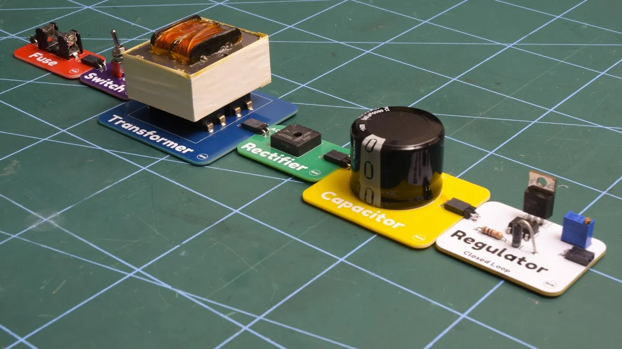
Linear Power Supply Components Explained: A Full Build Guide
@electrarc240
641K views•2024-10-16

33:39
How a Student's Question Saved a NYC Skyscraper from Collapse
@veritasium
22.8M views•2025-04-26
Related Study Plans & Knowledge Roadmaps
Structured learning paths in Engineering
engineering
Building Acoustic Levitators: Physics & Arduino
01The Physics of Sound and Standing Waves
02Piezoelectric Transducers and H-Bridge Drivers
03Arduino Programming: Generating 40 kHz Signals
+ 2 more learning modules
14h5 modules
Explore Roadmap
engineering
Building Peltier Cloud Chambers: Particle Tracks
01Cosmic Rays & Cloud Chamber Physics
02Thermoelectric Cooling (TEC) Fundamentals
03Custom Liquid-Cooling Loop Design
+ 2 more learning modules
18h5 modules
Explore Roadmap
engineering
Yagi-Uda Antennas: Modeling, Build & VNA Test
01Introduction to RF and Antenna Fundamentals
02Yagi-Uda Antenna Design Principles
03Antenna Modeling and Simulation in 4NEC2
+ 2 more learning modules
18h5 modules
Explore Roadmap
engineering
ECG Monitor Design: Op-Amps, Filters & Noise
01Electronics & Breadboard Basics
02Op-Amps and Instrumentation Amplifiers
03Bioelectricity and ECG Fundamentals
+ 2 more learning modules
18h5 modules
Explore Roadmap