
![Silniki DC | cz.2 - Mostek H | #64 [Podstawy]](https://i.ytimg.com/vi/YMECxKCmrfw/maxresdefault.jpg)
![🥇 Te enseño cómo funcionan los mosfet [PASO A PASO] 🥇](https://i.ytimg.com/vi/a6Ua6xrrrKM/maxresdefault.jpg)








![CAP #10►➰Bucles FOR y led en modo PWM 😱 - [Curso Arduino Español desde cero]](https://i.ytimg.com/vi_webp/9ilDctkuLXk/maxresdefault.webp)










![Building an Autonomous Robot From Scratch – Perceptron 🤖| Motor Driver [Ep.04]](https://i.ytimg.com/vi/fgswH4akRd0/maxresdefault.jpg)



An H-bridge motor driver uses four MOSFETs (two high-side and two low-side) controlled by a gate driver (IR2101) to enable bidirectional motor rotation and speed control; the gate driver requires a boosted voltage (20V) to properly saturate the MOSFETs, allowing the microcontroller to amplify its low-current signal into sufficient power for motor operation, with braking achieved by applying full PWM to both motor terminals simultaneously.
H-Bridge Motor Driver Tutorial: PCB Design, PXBX Ordering & Arduino Test
Added:Fundamental operation of DC motors and the basic concept of an H-bridge circuit for controlling rotation direction.
Working principles of MOSFETs (specifically N-channel), including gate threshold voltage and their operation as electronic switches.
Basic schematic capture and PCB layout design concepts in EDA software (such as KiCad, EasyEDA, or Altium).
Elementary Arduino programming, particularly configuring digital I/O pins and generating Pulse Width Modulation (PWM) signals.
Implementation of 'dead-time' in microcontroller firmware or hardware to prevent shoot-through current in the H-bridge.
Thermal management techniques in power electronics, including calculating MOSFET power dissipation and designing thermal vias or heatsinks.
Advanced PCB layout strategies for high-current paths, EMI mitigation, and proper placement of decoupling capacitors.
Integration of closed-loop feedback systems, such as PID control using motor encoders, to regulate speed and position.
Transitioning from single-phase H-bridges to three-phase inverter designs for driving brushless DC (BLDC) motors.
5.9K views169likes40:54Original Release: 2024-11-21
Hi, welcome to video tutorial from robotics. My name is Ahmad Shamshiri. In this video we are going to design a MOSFET based full bridge motor driver with HIGH side and LOW side with gate driver. I am going to use the IR2101 gate driver. This will have full speed control and direction of rotation on. And also I have implemented stop and braking feature in the code.
I am going to explain how the HIGH side and LOW side is being driven. Then I'm going to explain the schematic, and I'm going to show you the wiring diagram for the breadboard. So we can implement the project on the breadboard and test and place order online. And then I'm going to show you the wiring of the PCB and test our project.
First we some thought that was 50% and brake now. So most of this one of the best solution is to build an edge bridge. And but you need to use an UNP channel MOSFET and drive them properly so they work. A one way to do it is using gate driver. I use this IR2101and used all n channel must set.
This is IRFZ44N which are all n channel and that makes the design much easier. And also the design that I've implemented here is that you can run even three volts motor or maybe five volts up to 24V. So in order to make this gate driver work with all voltages I have use had a boost converter that gets 3.3V or five volts and converts it to 20V because gate source voltage is plus -20V.
So it's very safe to supply up to 20V through the gate. And this way it's fully saturated and it acts as a base switch. And also this muscle has a 17.5 million orders on when, drain source is turned on the resistor. The resistance is very LOW, relatively LOW of design. Everything in PCB. I've drawn the circuit, then produced the PCB.
I've made some connection later. on the actual PCB on the Gerber file.
But then I place order using PCB ICS servers, and I place order for five, and they shipped it to me and the product is perfectly working. It was my mistake to forgot. This was my mistake to forget one of these chips, to be connected to the ground.
So I put this wire. I didn't need to reorder. Initially, I designed it with, of the couplers to isolate isolated from Arduino. But there was some design defect.
because I made some mistake with the design, so I just eliminate it and use it without any, of the coupler. This space was empty. I incorporated, a rotary encoder.
Which I have not used that. In this video, I will provide you the Gerber file and also the schematic if you want to produce it. and get the deal from PCB, the link will be beLOW this video in the description.
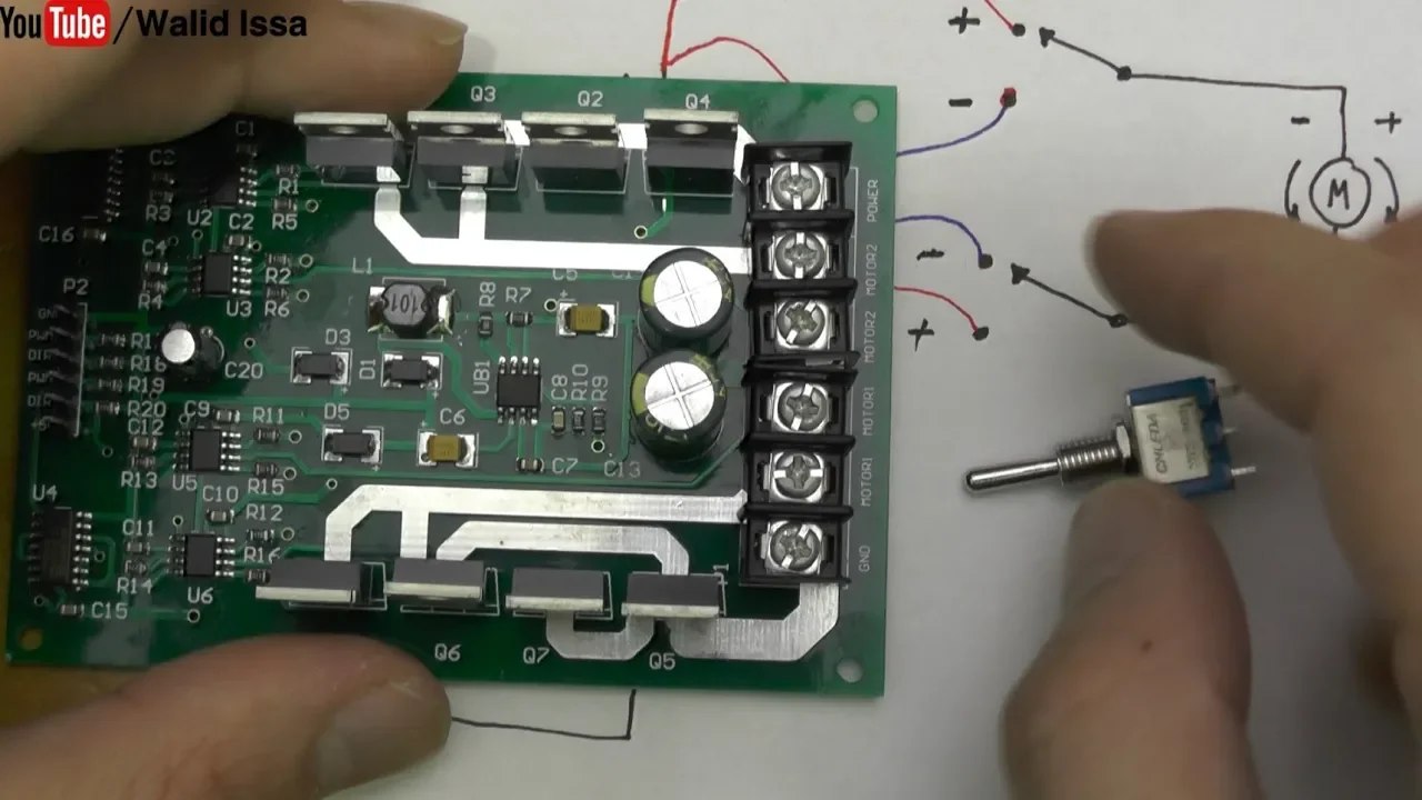
Now let's understand how the DC motor is controlled. This is our DC motor and this is our battery. We just connect a switch in between the motor and the battery, either at the positive wire or at the negative one. But most, most of the time preferred. And here, the positive. So we can turn it on and off.
Now, this, terminal is connected to the positive. The left side is connected to the negative.
And in this case, if it is connected, in this configuration, let's say the motor is rotating at CCW or counterclockwise. if we switch the positive which was before connected in here, now we bring it the, this seminal and the negative which was in here.
Move us to the other terminal. The motor will rotate in the clockwise direction before it was counterclockwise. Now it changes the direction of rotation. So we learned that if we change the polarity of the power to the motor, the direction of rotation changes and have. For this motor, I am connecting the negative to this terminal and positive to this terminal.
Pay attention. As you can see it goes counterclockwise. Now if I switch it connect it to this terminal. The negative is now here the positive is switched.
As you can see it's going clockwise. Now the question is why can't we just connect the motor directly to Arduino. Is P32 or Raspberry Pi? Whatever is it that you are using?
The answer is that the vector controller cannot supply enough power to the motor. because this motor, even if it's five volts and the output is five volt, this will not be able to run it because the amount of current, which is the unit, the unit is ampere is not enough.
This will supply, for example, ten milliamp hour or 15 or maximum 20 milliamp hour. But this will need 1200 milliamp are connected directly. And we need something called driver which gets the signal and amplifies it many, many times. And so we can control the motor.
Let us see how, each bridge works. This is our motor. The positive is connected to.
This is here. This is our power supply, battery or whatever. So if you have and this side is connected to the ground, this is a symbol for the ground or negative terminal.
Now if we in this case let us say this motor is rotating in the CCW direction or CW clockwise direction. The positive of the motor is connected to v6.
Now if we change it now the positive of the motor is now at the bottom. A negative is at the top which is connected to the positive. So in this case no the motor will rotate in the counter clockwise direction which we just explained. This is a bipolar junction transistor which has collector emitter and base. It has three terminals.
This is NPN but doesn't matter. I am just giving an example. So this transistor can be used as a switch. And I am just creating a similarity between these. So one side of switch is collector. The other side is emitter and base is where you push the switch. So you can on both turn it off like that. Click the create a configuration like this with four switches.
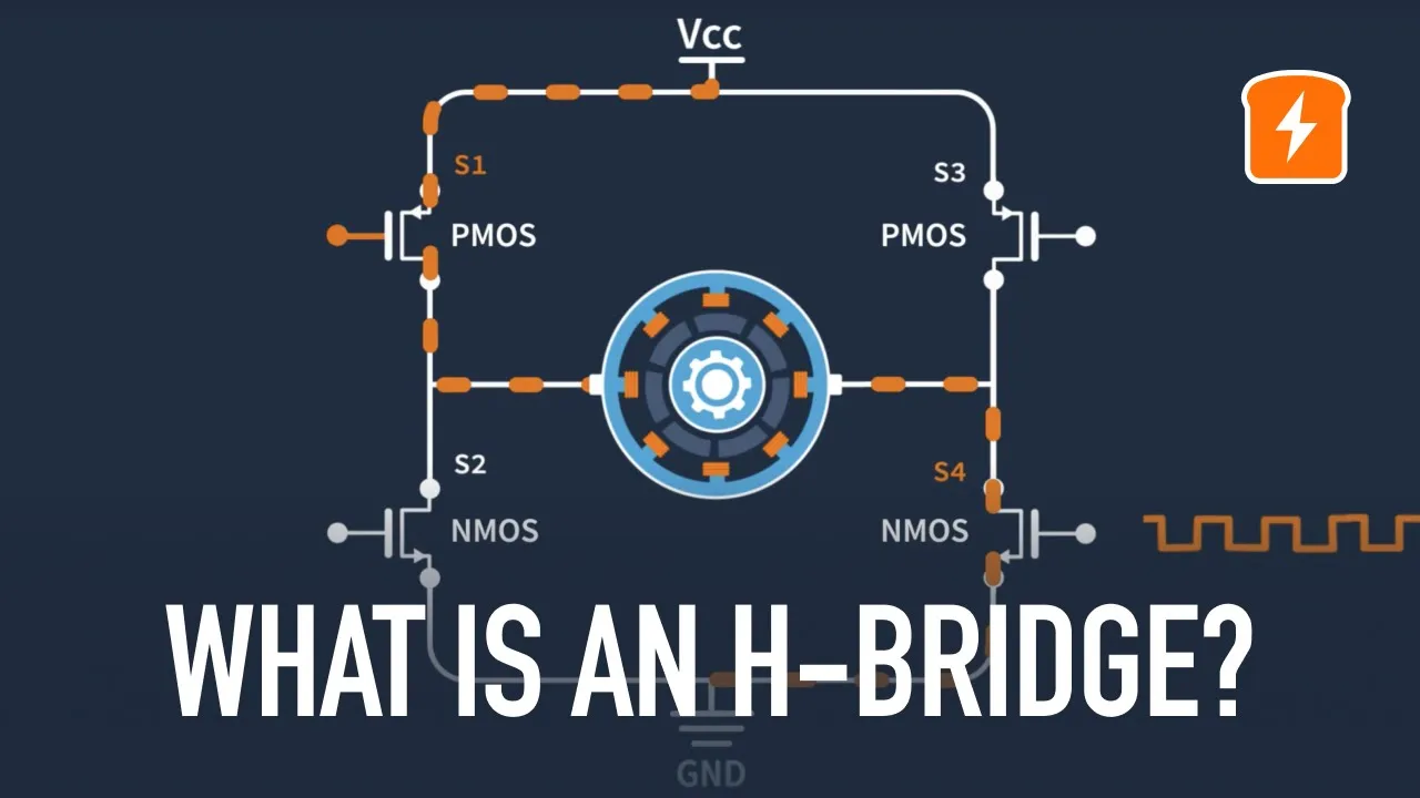
You see this w one switch 1234 connected to the motor like this. This is called H bridge because it looks like H. So and if we turn this switch on and this switch on, switch one and switch four, you will see that the current cannot go here because this is not connected. So the current will pass through, through which one passes through the motor goes to the switch four which is completed to the ground.
And the other result this motor will rotate, for example in a clockwise direction. But if we turn this switch one off, switch for off and turn on switch three and two at the same time. These two switches, then the current which before was coming to here, you see the VCC positive was connected to the negative. Now positive is connected through this because this is of through this to the positive.
This is now not connected. So it goes through the motor and exists from the negative terminal and connects to the negative as a result this will now rotate and counterclockwise before it was rotating clockwise. But now it goes counterclockwise. So using four switches we can control a motor easily.
And as I mentioned for instead of switch we can use the transistor as a switch.
So we can quickly turn it on and off and control the motor. This configuration also can be used for a brake or quick stop, where switch four and two is turned on and off when, because the motor was rotating, it generates energy and it itself, this sLOWs itself faster.
Or you can do it like this. So three and two is on because this positive just goes and circulates.
There is nothing connected to the ground or in this case nothing is connected to the VCC.
So there is no harm, but it can stop the motor quickly. Now the problem occurs if you connect or if you turn on S3 or S4. You see the positive doesn't go here. It passes through these two and there is a short circuit and oops.
So the fuse will bLOW up. Or maybe the wire there will be fire or something. And the same thing if you do turn on earth which one and two at the same time, the same thing will happin and there will be fires. Or if there is a fuse, the fuse will bLOW up. So this is how h approach works.
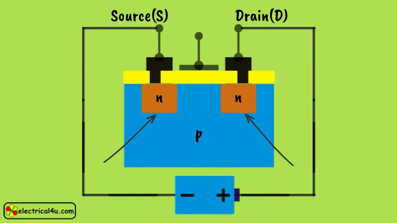
Oh, now when we use a MOSFET as a switch, this is a drain and source.
And we have to turn the gate HIGH to connect it. When gate is LOW, the switch is off, and when the gate is HIGH the switch is connected. Drain and source is connected.
So this will act like a switch. Now we can use the most of here.
This is just an example of third volts and this side is called HIGH side. This is called LOW side. The reason for the LOW side is that this is when this turns on. This is like a switch. So this is connected to the LOW side or the ground. And when this gate is HIGH this will turn on. This line will be short circuited.
This has very LOW internal resistance or drain source. Turn on resistance is called or this is on. This is located on this side connected to the power supply. This is called HIGH side. And the current will pass through and the motor will rotate. This adjusts in one direction. And we will have the same MOSFET in here and here.
When we go in the other direction. Because I just explained that we are going to show you only this one. Now the motor will rotate, let's say in counterclockwise direction. In order to turn on a MOSFET. This particular MOSFET needs 2 to 4V between source and gate. The gate source voltage, which means gate must be 2 to 4V.
Let's take it. Average three volts higher than source. So. And also this one, also three volts. This gate must be three volts higher than this ground. So when we say higher than ground then the three volt will work fine here and this will turn on. But the problem is this motor needs 12 volt. When the MOSFET is turned on, the 12 volt is coming here.
So we have here 12V. So the so the 12 volt is on the motor and this side is now 12 volt. Now if this is true or false then from ground the gate should be the voltage of the motor plus three volts meaning this is 12V. And the gate voltage is let's say four volts. So four plus two.
This must be 16V.
If it is three then it will be 12 plus three 15V. So this is 12V. Where do we get 15V. That is where gate driver come in and it will supply. So we need 15V to turn this MOSFET on. And here this is I r IR2101connected to this MOSFET. I'm just showing you here and we have HIGH and LOW end signal.
When HIGH end is HIGH then HIGH out will be HIGH. And this switch will turn on the LOW. And this can be connected to the other MOSFET which I've not shown it. So and the input voltage comes there is a capacitor. And this side is connected to one side of the motor. And this will drive the gate for us.
And that's what we do in this video.
Ahead of the schematic on the left side we have a boost converter that receives five volts. This can work even 3.3V and it will convert it to 20V. So this is MT 3608 with this inductor and then Schottky that we have a potentiometer that we can set the output voltage output voltage of here 20V. So we will connect a jumper here to turn it on and off for some test purpose.
And then.
This is the power supply input that comes to this drain of this MOSFET. We have four MOSFETs I, rf z 44 and two are HIGH side Q1 and Q3. And then Q2 and Q4 are the LOW side. All the fans are being driven using this. I r IR2101chip. 20V that we generated here is coming to this chip.
And then we have another chip. The chip has HIGH and LOW end which is connected via one kilo processor to Arduino. In this case. And the output.
HIGH out and load HIGH out is connected using ten ohm resistor to the gate of HIGH side and from the other end as well the HIGH out is connected to the HIGH side and the LOW is LOW, disconnected from one side to the other one to Q4, and from this side it is connected to Q3 to Q2. Q2 the motor is connected between these two points, between the source and drain of the southwestern source and drain of Q1 and Q2 and Q3 and Q4.
Then both have five terminals, two for one HIGH and LOW input and two for the other one and one ground. This project that you are watching is produced using high quality products from PCB.
PCB, ECS can produce your PCBs or they can do full assembly PCB movement for each new user. They offer ten PCBs for a dollar, or you can do full assembly of ten PCBs for free.
The process is very simple. You click on PCB code, upload your Gerber files.
Review your product.
Select the options and terms of quality of material, number of layers, thickness and tons of other option and place your order. You can draw your schematic by selecting the components. Then decided that we wanted preview it.
As a 3D model.
Once you are satisfied, you can click Place Order either Place Order PCB or Place Order for PCB of full assembly. If you select PCB, for example, you don't need to upload the Gerber file or anything. All the information that comes directly from, the EDA. You will see all the layers of your Gerber file. You can also view it in 2D, and also you can preview the 3D of the PCB, add it to the cart, and place your order.
If you wish to place order for high quality, fully assembled project, click on Order and Order PCB. A. The same as a Frisbee. You will have options.
You have the option to preview it. Preview the Gerber file. Preview the 2D. Preview 3D of your project. Select the component based on the type and quality and request for the code. They will contact you about the cost, or you can use the free assembly of ten PCB option here. The link is beLOW the video. You can click and place order.
Now let me explain the code we have defined here Pin nine, eight, three and two for Pulse Width modulation (PWM). This is the HIIN1 pin the 9. The LIN1. So this was HIN1 and LIN1. That is for one chip 8 and 9. Pin nine must be the pulse width modulation PWM. Enable pin and then pin two and three.
Or for HIN2 and LIN2 pin three. Must be this pin high two must be PWM pin. And these are the pin that labels on the, actual breadboard.
So the label that we have here will match the code that you see.
So PWM1. And this is PWM1. EN1. PWM2, EN2. These are on the breadboard on the PCB. Do not change this. We are defining clockwise and counterclockwise as zero and one. And these are the prototypes of the functions that are at the bottom of the code.
Inside the setup we initialize the serial monitor and PM1, EN1, PW2, EN2 using pinMode we define them as output. And then inside the loop. This is how we call if we want more to run at clockwise and 100%, we just say Motor(CW, 100) And this is the amount of time that we want a delay or some other action.
So the motor will run unless you have a delay it will not run. So this delay is keeping it running for five seconds and then brake. If you want to brake just say brake(). So calling this function will brake. And here it says brake for three seconds. And then we say run the motor and clockwise at 100% for five second.
And then a stop brake is to bring the motor quickly to stop. And stop is just coasting, turning the power of and the motor runs until it will stop. And then this is saying that run the motor 50% and counter clockwise and then brake. This is just a loop for learning purpose. We initialize I from zero up to 100.
So this I changes. Here we say motor clockwise II0 1 to 3. It goes up to 100%. And every time we have 100 seconds delay. So this is incrementing because it's plus plus this is decrementing. It. This starts at. 100%. And it goes up to zero and then brake. So now the stop() stop is just turning LOW LOW LOW and then HIGH.
As you can see here, this also could be but brake is very important for the brake. As I explained it. We have to have this PWM1and PWM2 both of these HIGH and the other two should be LOW. This will cause the motor to brake. And this is printing by the way, if you don’t need it because it uses some resource.
just comment this out and it will not be displayed. And then this is the motor() function that we call this is the direction and that's the speed. And then we and using this map we convert the speed which is from 0 to 100. We map it to be value from 0 to 255 which is used by Arduino here.
And then this is just printing the text and we check if the direction is C w. Then we turn on the motor like this. So PW1, EN1 is HIGH and with a speed and the other is LOW. This is a second chip. But if it is CCW then the top is LOW, the bottom is HIGH and speed.
This was the top. HIGH speed and LOW was zero. This was the full explanation of the code.
And here is the wiring for breadboard. I've used two breadboards because, it will be too cluttered. Still. I have five volts here from the left side. The five volts is coming to this point where it goes through this module to convert it to 20V.
this module, I'll provide you the link if you want to purchase it.
And because I did not use the ground because ground is used this way here to the breadboard and then all the inputs pin eight, nine, two and three, they all come through one kilo ohm resistor and then gets connected. The most important part is to remember is this black wire.
Because if you do all the wiring, if you don't do this black wire, the motor will not run.
Then the battery, the battery can be even five volts, three volts up to 24V. Because, the operating voltage for this, Because the capacitor that I use is, less than 24V. So if you want to use higher voltage for the power supply, that's fine. Even higher voltage will work fine. And then.
These diodes or this is I r IR2101and then, these are ten ohm resistance one two and three. And I believe there is one more. Yeah. It's be LOW this. After this blue there is one more resistor I've cover that. I'm going to fix it that I uploaded. So you can do the wiring from this as shown here.
I will provide you with this wiring in the resource page for this video.
That is, setup and wiring. Everything is ready. I have the power supply that is connected, which is our supply. If I measure the voltage around nine volts, 9.2V, and then it goes to this boost converter.
Which is I is just push this converter. This side is the input. And this is output that receives maybe two three volts and a voltage of five volts. And we are getting 20V. I have covered that through a tape so it doesn't make short circuit here because it was already exposed on the breadboard. You can see this is my 20V.
It is five volts. So now the code is running. If I open the serial monitor.
We see that this is now running clockwise and counterclockwise.
The motor is not connected. So I am going to connect the motor.
And.
Now this is brake. And then let's see how.
That was brake, which was quick and.
This will stop now. Brake!
So, it works perfectly on the breadboard, and, currently, the amount of current and.
000.
Oh, oh. The current is 1.24A for this at nine volts.
Now, let's say your order is completed. You can just click order PCB as just a PCB. PCB a means assembly. So let's click this.
And here we will see our order. All the. Information is here port number information.
As you can see for five pieces. Lead time eight. This part cost $27. PCB costs $5. Global shipping $8. And here are the other settings. The type of, PCB number of layers, a thickness board type. And the rest of the soldered mask, whichever way, whichever color you want, you can select it.
I am going to go with green. So this is the 2D view of what we see. And here the 3D.
And it doesn't show the.
Buttons.
So now check out. So after placing order the package has arrived.
Whoa! Multiple layers of protection.
So each packages protect it, making sure that these capacitors do not bend the PCB on this side. We have a terminal for. It can work even with the 3.3V or five volts. So this there is an input with five volts. And then we have the power supply. This is the same power as your motor.
So if your motor is 12V connect 12V.
If it's 24V can I 24V. If the motor is even five volts. Connect five volts here and the motor will be connected. this side then we have the data input on this side where this will be connected to your, pulses modulation and signal control, like Arduino Esp32 or Raspberry Pi, if you wish. And then we have four motors.
This this connector. This is a potentiometer where we can set the voltage. The five volts is coming using this boost converter. It converts to 20V. And the method pin is the output. And this is this. This is a placeholder for the rotary encoder in case if you want to control the speed of motor or whatever, using the rotary encoder and with the required resistors already included, I try to put some information here for the voltage.
And current.
These are the gate drivers I r 20 101. And then we have four MOSFETs. These are the I r of Z 44 N. All of them. These are some one side HIGH side LOW side. And this is for the other side. This is the HIGH side and LOW side because the HIGH side is getting hotter. So I put them on the side.
if needed we can include larger heatsink. But here also we have some room for smaller heatsink. This rotary encoder I've chosen for this motor driver.
Let's just see if it sits.
Let's put this knob here.
And I've connected my multimeter at the input. If I connect this, we see five volts. This is a wire for the multimeter. And I'm going to connect it to the metal terminal here. This is the output voltage from this boost converter.
Now this is increasing.
So I set it to 20V. So the output is set to 20V.
Now because we are not going to use the rotary encoder. And in order not to confuse you I am simply covering this. So this will not be used. Now I'm going to connect this terminal and this terminal the middle to this side. So we can have 20V supplied to the gate.
Now has been connected.
And here for the wiring I have connected five volts to this part. Five volts is connected to Arduino. This is getting five volts and converting it to 20V.
And then these two metal wires, these are connected to my power supply. The last two wires are connected to my motor. I'm going to connect this little.
For the Arduino I've. We don't need this ground because already I have a ground that I already connected it. So the first one is connected to the ground or just connected the pin two yellow is connected to pin three, green to pin eight and blue to pin nine.
And here is a demonstration. The motor. Everything is ready. As you can see, Arduino also shows the code. Currently it goes from 0 to 100% and from 100 back to zero. And as soon as they connected, I am going to explain it. So let's connect the motor. Oh, I, I'm going to reset it so it goes.
So first it goes with high speed clockwise and then brakes to stop it very quickly. Let me connected reset. Now it goes.
It was brake. And.
It changed direction. And also it stopped. It just went slowly.
And now it will go with the slower speed. Let me do it again. And.
So the brake and then counterclockwise.
Now it will speed up slowly 50%. So that was 30%. Then brake. And now slowly increases.
And that's percent. And now decreasing.
And brake. Oh. So this was a demonstration. amount of current was one point. let me check it again. How much was it? Oh.
100%. And this something is.
An.
The voltage is 12V.
And so, at 100% perfect modulation, it was 1.7A. And these transistors are very cool. They do not need even heatsink for 1 or 2 amperes.
Here, as you can see, this can go up to 49 amperes. This is huge. Of course it needs huge heatsink. More than two amperes. More than two amperes. You need to put some small heatsink. But if you want to go 5 or 10 ampere you need proper cooling. Thank you for watching. This was a full bridge using, Moss Further and Gate River.
The PCB have been produced in PCBx. The excellent deals at the moment. The link is below this video. If you want to place order, make sure to thumbs up the video and also subscribe to my channel. I appreciate it.
Up Next

8:14
Regenerative Braking Efficiency in Electric Bikes: A Quantitative Analysis
@TomStantonEngineering
147.7K views•2017-11-30

30:32
Ultrasonic Transducers: Resonant Frequency Measurement and Horn Design
@imajeenyus42
229.9K views•2017-02-22

54:16
Polymer Environmental Degradation: Mechanisms & Stabilization
@iit
1.8K views•2012-07-10

33:39
How a Student's Question Saved a NYC Skyscraper from Collapse
@veritasium
22.8M views•2025-04-26
Related Study Plans & Knowledge Roadmaps
Structured learning paths in Engineering
engineering
Building Acoustic Levitators: Physics & Arduino
01The Physics of Sound and Standing Waves
02Piezoelectric Transducers and H-Bridge Drivers
03Arduino Programming: Generating 40 kHz Signals
+ 2 more learning modules
14h5 modules
Explore Roadmap
engineering
Building Peltier Cloud Chambers: Particle Tracks
01Cosmic Rays & Cloud Chamber Physics
02Thermoelectric Cooling (TEC) Fundamentals
03Custom Liquid-Cooling Loop Design
+ 2 more learning modules
18h5 modules
Explore Roadmap
engineering
Yagi-Uda Antennas: Modeling, Build & VNA Test
01Introduction to RF and Antenna Fundamentals
02Yagi-Uda Antenna Design Principles
03Antenna Modeling and Simulation in 4NEC2
+ 2 more learning modules
18h5 modules
Explore Roadmap
engineering
ECG Monitor Design: Op-Amps, Filters & Noise
01Electronics & Breadboard Basics
02Op-Amps and Instrumentation Amplifiers
03Bioelectricity and ECG Fundamentals
+ 2 more learning modules
18h5 modules
Explore Roadmap