This video tutorial demonstrates how to create a functional wind turbine model using cardboard materials, suitable for school science projects; the model uses a standing fan to simulate wind and generate rotational movement, illustrating basic principles of renewable energy conversion through hands-on construction.
Wind Turbine Model from Cardboard: DIY School Science Project
Added:Deep Dive
Basic understanding of kinetic energy and how wind is formed by atmospheric pressure differences.

2025 MEB AGS/KPSS COĞRAFYA GENEL TEKRAR İKLİM BİLGİSİ 2
86.1K
Wind is formed due to pressure differences in the atmosphere. The pressure unit is millibars. When there is a pressure difference between two areas, air moves from high pressure to low pressure to balance the difference. The greater the pressure difference, the faster the wind speed. When pressure equalizes (e.g., both areas at 105 millibars), wind ceases.
Click to watch →
![[중③ 2단원] 6-1강. 바람이 부는 원리│해풍 & 육풍│계절풍│고기압 & 저기압🌤](https://i.ytimg.com/vi/3DAqKF3CAOk/maxresdefault.jpg)
[중③ 2단원] 6-1강. 바람이 부는 원리│해풍 & 육풍│계절풍│고기압 & 저기압🌤
296.5K
Wind is formed by differences in atmospheric pressure. When two regions have different temperatures, the heated region causes air to expand and rise, reducing air pressure near the surface. The cooled region causes air to contract and sink, increasing air pressure near the surface. Air naturally moves from areas of high pressure to areas of low pressure to equalize the distribution. This movement of air near the Earth's surface is called wind.
Click to watch →

Атмосферное давление Ветер
721
Wind is the horizontal movement of air from areas of higher atmospheric pressure to areas of lower atmospheric pressure. The greater the pressure difference, the stronger the wind. Temperature differences cause pressure differences: warm air has lower pressure (expands and rises), while cold air has higher pressure (contracts and sinks). Sun angle causes temperature variations: the equator receives the most direct sunlight and heat, while polar regions receive less. This creates pressure gradients that drive wind circulation.
Click to watch →

طبقات الغلاف الجوي - الدرس الأول وحدة تانية - علوم تانية اعدادي ترم أول 2025 (جزء أول)
29.4K
Wind (الرياح) forms due to differences in atmospheric pressure between different locations. Air moves from areas of high pressure (marked with 'H') to areas of low pressure (marked with 'L'). This movement of air from high to low pressure creates wind.
Click to watch →

حل اختبار 1 اختبارات عامه على المنهج علوم متكامله كتاب الامتحان الترم الاول 2025
37.9K
Wind is generated by differences in atmospheric pressure between two regions. Air moves from areas of high pressure to areas of low pressure. The greater the pressure difference between regions, the faster the wind speed. When pressure is equal between regions, no wind forms.
Click to watch →
Deep Dive
The Law of Conservation of Energy, specifically how mechanical energy can be transformed into electrical energy.

المراجعة المركزة | فيزياء السادس العلمي | جميع شرحيات الفصل الثاني في محاضرة واحدة
111.2K
When a conductor moves through a magnetic field to generate electricity, mechanical work is done to move the conductor. This mechanical energy is converted into electrical energy, which is then dissipated as heat in the circuit. This demonstrates the law of conservation of energy: energy is neither created nor destroyed but transformed from one form to another. The mechanical work done equals the electrical energy generated.
Click to watch →

Mechanics Part 6
11.1K
The law of conservation of energy states that energy cannot be created or destroyed, only transformed from one form to another. The total energy of an isolated system remains constant. Energy transformations include: chemical to electrical (batteries), electrical to light (light bulbs), electrical to mechanical (motors), mechanical to electrical (generators), and light to electrical (solar cells). These transformations demonstrate that energy changes form but the total amount remains constant.
Click to watch →

مراجعه الفصل الاول -الشغل والطاقه -فيزياء تانيه ثانوي ٢٠٢٦ الترم التاني |متبقاش جهاز
230.7K
Mechanical energy is the sum of kinetic and potential energy: ME = KE + PE. The law of conservation of mechanical energy states that ME remains constant in an isolated system. Energy can transform between forms: potential to kinetic (falling object), chemical to mechanical (car engine), electrical to light and heat (bulb). At maximum height, PE is maximum and KE is zero. At impact, PE is zero and KE is maximum. At midpoint, PE equals KE.
Click to watch →

Plus Two | Physics പരീക്ഷയ്ക്ക് പോകുന്നതിന് മുൻപ് പഠിക്കേണ്ട 55 IMPORTANT QUESTIONS
66.5K
According to the conservation of energy principle, mechanical energy can be converted into electric energy. This fundamental law states that energy cannot be created or destroyed, only transformed from one form to another. In the context of electrical systems, mechanical work can be converted to electrical energy through various mechanisms such as generators and motors.
Click to watch →

ETT Cadre Science 2026 | Work & Energy One Shot | Target 40/40 MCQs | Punjab ETT Exam By Brar Sir
952
The Law of Conservation of Energy states that energy cannot be created or destroyed, only transformed from one form to another. The total energy in an isolated system remains constant. Energy transformations include: solar cells converting light to electrical energy, batteries converting chemical to electrical energy, candles converting chemical to light and heat energy, and generators converting mechanical to electrical energy. Mechanical energy is the sum of kinetic and potential energy: ME = KE + PE.
Click to watch →
Deep Dive
An introduction to simple electrical circuits, including concepts of voltage, current, and basic components like LEDs.

Basic Electronics Series - Session 1 | Understand the concept of Battery and LED | Basic Electronics
401
In basic electronics, voltage represents electrical potential (like water pressure in a tank), current represents the flow of electrical charge (like water flowing through a pipe), and a circuit is a closed path connecting a power source (battery) to a load (LED). To design a simple circuit, connect the positive battery terminal to the LED's anode (longer leg) and the negative terminal to the cathode (shorter leg), ensuring proper polarity for the LED to function correctly.
Click to watch →

Eletrônica Descomplicada. Introdução aos Circuitos para Iniciantes
718
Electrical circuits are governed by three fundamental quantities: voltage (tensão), current (corrente), and resistance (resistência). The water analogy helps visualize these concepts: voltage is like a pump pushing water, current is the water flowing through pipes, and resistance is obstacles impeding flow. A circuit is a closed path where electricity flows from a power source, through components, and back to the source. The Arduino board provides power through specific pins: GND (Ground) represents the negative terminal, while 5V and 3.3V pins provide positive voltage. When building circuits on a protoboard, wires connect different points through horizontal and vertical lines. Wire color coding helps identify polarity: red typically represents positive, black represents negative. LEDs are polarized components requiring correct orientation: the anode (larger leg) connects to positive, and the cathode (smaller leg) connects to negative. When connecting LEDs to 5V sources, a resistor must be placed in series to limit current and prevent burning out. A common value is 330 ohms.
Click to watch →

Mạch Điện - Điện Tử Cơ Bản - Tập 1 | Học Nghề Kỹ Sư Điện & Điện Tử
79K
An electrical circuit is a closed path allowing current to flow. Circuits can be closed (complete) or open (broken). Basic circuits require a power source (battery), a load (like a light bulb), and conductive wires. Batteries have positive and negative terminals providing voltage. Components like switches control circuit continuity. LEDs require correct polarity to function, unlike incandescent bulbs which are less sensitive to voltage variations.
Click to watch →

Kips Cyber Quest,DAY-7 | 20Mins Challenge-Tinkercad for Grade 7 Computer
268
An electrical circuit is a closed path connecting power source terminals through wires and devices. Common power sources include 9V batteries, 3V coin batteries, and 1.5V cells. Components like LEDs require proper polarity connection (anode to positive, cathode to negative). LEDs have two terminals: anode (positive) and cathode (negative). The circuit must be complete for current to flow and devices to function.
Click to watch →
Basic Electronics Circuit Topics for Beginners Learning
542
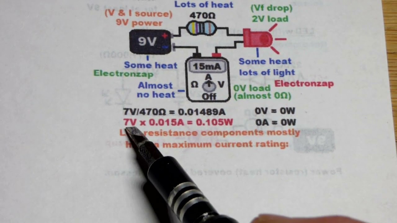
A basic electronic circuit consists of four essential components: a power supply providing voltage, a load (such as an LED) consuming power, a resistor controlling current flow, and optionally a switch for activation. Red LEDs require approximately 15mA for optimal brightness and have a forward voltage drop of about 2V. Using Ohm's Law (I = V/R), current through an LED circuit equals the voltage across the resistor divided by its resistance. For a 9V battery with a 470Ω resistor, this yields approximately 15mA of current flowing through the LED.
Click to watch →
Deep Dive
Fundamental mechanical concepts such as rotation, axles, and how physical shapes interact with moving fluids (air).

12TH PHYSICS MOST IMPORTANT QUESTIONS FOR 1 & 2 MARKS | BOARD EXAM 2025 | JR COLLEGE |
124.4K
This comprehensive section covers fundamental physics concepts: (1) Rotational Dynamics - centripetal/centrifugal forces, moment of inertia (I = ½MR² for disk, 2/5MR² for sphere), Parallel Axis Theorem (I = I₀ + md²), Conservation of Angular Momentum, and moment of inertia formulas for various shapes. (2) Fluid Mechanics - pressure due to liquid column (P = ρgh), gauge vs total pressure, Pascal's Law with hydraulic lift applications, surface tension (N/m), surface energy, Laplace's Law for bubbles/drops (P-P₀ = 2T/r or 4T/r), capillarity, critical velocity (v_c = η/ρr), Reynolds number (Re = ρvd/η) determining laminar/turbulent flow, viscosity (F = -ηA(dv/dx)), Stokes' Law (F = 6πηrv), and Bernoulli's Principle based on energy conservation.
Click to watch →

MHTCET FULL PHYSICS IMPORTANCE & STRATEGY (Detailed) TIPS TRICKS for MHTCET PHYSICS 2021 #rglectures
9.2K
Rotational Dynamics covers: (1) Moment of inertia - resistance to rotational acceleration; (2) Angular momentum - rotational equivalent of linear momentum; (3) Conservation of angular momentum; (4) Moment of inertia for various shapes (solid sphere, hollow sphere, rod, disc). Any object moving in a circular path requires centripetal force directed toward the center. The source of this force depends on the situation: gravitational force for planets, tension for stones on strings, friction for cars turning, and normal force for particles on tables. Mechanical Properties of Fluids covers: (1) Surface tension - force per unit length at liquid surface; (2) Viscosity - resistance to fluid flow; (3) Reynolds number - determines laminar or turbulent flow; (4) Terminal velocity - maximum velocity of falling object.
Click to watch →

🚧 Fluid Mechanics Fluid Properties New Updated 2025-26 | Up Polytechnic 3rd Semester Chapter-1 Lec-1
4.1K
Fluid Mechanics (तरल यांत्रिकी) is a branch of mechanics studying forces acting on fluids and their effects. It is essential for Mechanical, Civil, and Chemical Engineering students. Matter is anything with mass that occupies space. In our atmosphere, there are only three states of matter: Solid, Liquid, and Gas. Fluid is a term for both liquids and gases. Solids have definite shape while fluids take the shape of their container. There are two types of axes in mechanics: Longitudinal Axis (अनुदैध्य अक्ष) taken along the longest dimension of a body, and Transverse Axis (अनुप्रस्थ अक्ष) taken along the shortest dimension. These axes are imaginary lines used to describe the orientation and dimensions of objects.
Click to watch →

Physics 30+ Fix | Part 1 | Sahyadri Tutorials | Mahesh Sir #jeemains #jeemains2026
11.2K
This section covers fundamental concepts in mechanics and fluid dynamics. Key topics include Moment of Inertia (algebraic sum of mass times distance squared from rotation axis), Centripetal vs Centrifugal Force (real vs apparent forces), Law of Conservation of Angular Momentum, Capillarity (liquid rise/fall in narrow tubes), Surface Tension and Surface Energy, Viscosity and Viscosity Gradient, Streamline vs Turbulent Flow, Newton's Law of Viscosity, Pascal's Law, and Stokes' Law. The section emphasizes understanding definitions, distinguishing between similar concepts, and applying laws to solve problems.
Click to watch →
Supera los ✅ TEST DE APTITUD MECÁNICA. Con soluciones razonadas. (Parte 2) 40 preguntas
41.9K
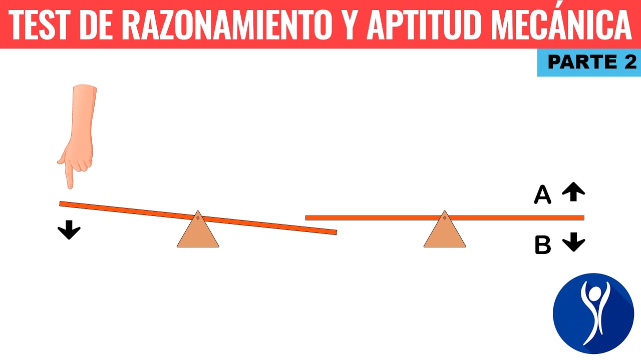
This section covers fluid dynamics and aerodynamic principles including Bernoulli's principle (faster air creates lower pressure, causing objects to attract), fluid velocity and exit height relationship (greater height above opening increases velocity), and shadow formation (shadow size depends on light source distance). The section also covers gear and rack mechanisms for cutting, and how mass distribution in wheels affects rolling distance (outer mass provides more rotational energy for longer travel). These principles demonstrate how fluid behavior and mass distribution affect mechanical systems.
Click to watch →
Prerequisite Knowledge
- Concept 01Basic understanding of kinetic energy and how wind is formed by atmospheric pressure differences.
- Concept 02The Law of Conservation of Energy, specifically how mechanical energy can be transformed into electrical energy.
- Concept 03An introduction to simple electrical circuits, including concepts of voltage, current, and basic components like LEDs.
- Concept 04Fundamental mechanical concepts such as rotation, axles, and how physical shapes interact with moving fluids (air).
Subsequent Learning
- Step 01The physics of blade design, exploring how blade pitch, surface area, and aerodynamic lift affect turbine efficiency.
- Step 02Faraday's Law of Induction to understand the internal workings of electric generators and motors.
- Step 03Challenges of renewable energy integration, such as grid stability, energy storage systems (batteries), and power transmission.
- Step 04Environmental and economic impacts of large-scale wind farms, including wildlife considerations and lifecycle assessments.
Opening Applause
Main Music
Music Peak
New Segment
Rhythm Shift
Audience Cheer
Melodic Bridge
Final Build
Closing Crescendo
Opening Applause
0:14Playing Section
- 1
Audience claps as event begins.
- 2
Momentum builds with rhythmic clapping.
- 3
Atmosphere shifts from quiet to engaged.
The Limitations of Cardboard Modeling vs. Digital Simulation in STEM
While building cardboard wind turbines offers a tactile, hands-on experience, critics in STEM education argue that such simplistic models can foster misconceptions about engineering and physics. Cardboard lacks the structural integrity to withstand realistic aerodynamic forces, and these DIY projects rarely generate measurable electricity, failing to demonstrate actual energy conversion. An alternative approach advocates for digital simulation software (such as Computational Fluid Dynamics tools). Digital simulations allow students to test real-world variables—like blade pitch, wind velocity, and lift-to-drag ratios—with mathematical accuracy. Proponents of this view argue that computer-aided design teaches modern engineering skills and provides a more scientifically rigorous understanding of renewable energy than crude physical crafts.
Deep Dive
The physics of blade design, exploring how blade pitch, surface area, and aerodynamic lift affect turbine efficiency.
W5L1_Turbine Basics
255
Turbine blades transfer energy between rotor and fluid (gas, liquid, or steam) through aerodynamic forces. Blade components include hub (central connection), blade (rotating element), tip (outer edge), leading edge (fluid entry point), trailing edge (fluid exit), suction surface (upper curved surface), and pressure surface (lower curved surface). Blades are designed using airfoil shapes with thicker leading edges and thinner trailing edges, created by connecting multiple airfoil sections from hub to tip. When fluid flows over airfoil-shaped blades, lift force acts perpendicular to flow direction while drag force acts parallel, opposing motion. The lift-to-drag ratio determines blade efficiency.
Click to watch →

WHAT AIRFOIL FOR WIND A TURBINE BLADE PART 1
961
This extended section explores the physics governing airfoil performance and blade optimization. It covers zero lift angles, lift-to-drag ratios, and Reynolds number effects on efficiency. The video explains how asymmetric airfoils generate lift at negative angles, enabling negative pitch configurations that reduce rotational resistance. Critical concepts include the 25% chord rotation axis point, where lift vectors provide forward components that minimize induced drag. The section demonstrates how blade orientation determines energy transfer direction—horizontal axis turbines curve downward to extract energy while fan blades curve upward to push air. These principles show that strategic blade design exploits aerodynamic forces to maximize efficiency, with optimal configurations minimizing unnecessary work while maximizing useful output.
Click to watch →
Lec 34 : Turbine terms, types and theories: Part I
11.7K
Wind turbine blades utilize airfoil sections with specific geometric parameters: chord length (leading to trailing edge distance), thickness (upper-lower surface distance), camber line (midpoints of thickness measurements), and camber (distance between camber line and chord). High thickness-to-chord ratios maximize lift force. Lift is generated through two principles: Bernoulli's principle states that faster-moving air over the longer upper surface creates lower pressure, producing upward force; Newton's third law explains that air deflected downward by blade surfaces creates equal and opposite upward reaction force. The angle of attack—the angle between relative wind and chord line—controls lift magnitude, with higher angles producing greater downward air deflection and thus more lift. Horizontal axis turbines feature multi-blade systems (12-20 blades, 2-5m diameter) for water pumping and propeller-type systems (2-3 blades, 30-115m diameter) for electricity generation.
Click to watch →

Gerador com motor de maquina as pás eu n tenho um deste 6
12K
Wind turbine blade designs significantly impact efficiency. The Black Bird design has a closed shape with good exit area but poor attack area. The turbine blade design is simpler with a large attack area and good drag. The turbo fan blade is straight and optimized for high speeds. The Dragonfly design uses stepped surfaces to capture more wind. Blade count affects performance: more blades increase wind resistance but may create vacuum at high speeds. For speeds below 600 RPM, 3-4 blades provide better stability. The turbine must function from any wind direction due to its vertical axis design.
Click to watch →

Energia do Vento e Turbinas Eólicas
8.7K
Wind turbine blades experience two primary aerodynamic forces: drag force (acting in wind direction) and lift force (acting perpendicular to wind flow). Lift force is the primary mechanism for energy extraction in efficient turbines, similar to airplane wings. The angle of attack (α) is the angle between blade surface and incoming wind. Low angles of attack maximize lift and efficiency, while high angles increase drag and reduce efficiency. Beyond critical angles, flow separation causes turbulence and further losses. The pitch angle (β) is complementary to angle of attack (β = 90° - α) and is adjusted to optimize performance under different wind conditions.
Click to watch →
Deep Dive
Faraday's Law of Induction to understand the internal workings of electric generators and motors.
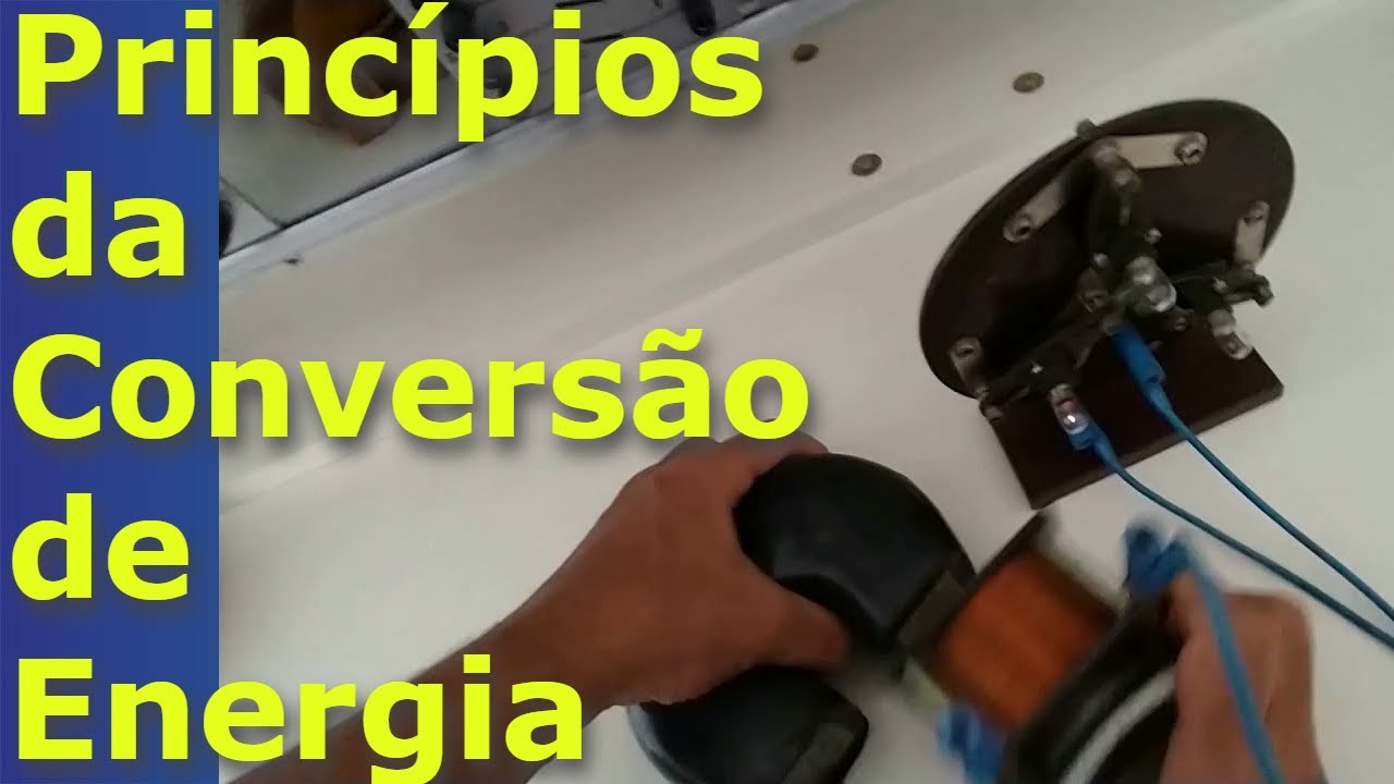
Fundamentos de MÁQUINAS ELÉTRICAS | Como funcionam os geradores ou motores elétricos? #01a
47.5K
Faraday's Law states that a changing magnetic flux through a conductor induces an electromotive force (voltage). When a permanent magnet moves relative to a coil, the changing flux induces voltage measurable with a voltmeter. Stationary magnet produces no voltage; relative motion is essential. This principle forms the basis of generators, where mechanical motion of conductors through magnetic fields produces electrical energy. The induced voltage depends on magnetic field strength and conductor speed.
Click to watch →

LIVE🔴 | 10TH SCIENCE 1 LMR REVISION | CHAPTER - 1 & 4 | BOARD EXAM 2024 | JR TUTORIALS |
54.7K
This section covers electromagnetic devices: An electric motor converts electrical energy to mechanical energy using a permanent magnet, coil, split ring commutator, and carbon brushes. Forces on opposite coil sides cause rotation. A galvanometer detects small currents by measuring coil deflection. Electromagnetic induction (Faraday's Law) states that changing magnetic flux through a coil induces an electric current. Fleming's Right-Hand Rule determines induced current direction: thumb (motion), index finger (magnetic field), middle finger (induced current). An electric generator converts mechanical energy to electrical energy by rotating a coil in a magnetic field, producing alternating current.
Click to watch →

Class 12 Physics Derivations One Shot | All Important Derivations Of Physics Class 12 | UP Board RWA
435.2K
Faraday's Law states that induced EMF equals the negative rate of change of magnetic flux: ε = -dΦ/dt. The negative sign (Lenz's Law) indicates the induced EMF opposes the change in flux. For a coil with N turns, ε = -N(dΦ/dt). This principle forms the basis for electric generators and transformers.
Click to watch →
جميع كلاميات الفصل الثاني /الدور الثاني + دخول شامل
38.6K
Electromagnetic induction is the phenomenon where a changing magnetic flux through a closed circuit induces an electromotive force (EMF), described by Faraday's Law: ε = -N(dΦ/dt), where the negative sign indicates the induced EMF opposes the change in flux (Lenz's Law). This principle enables the conversion of mechanical energy to electrical energy in generators and motors, and is fundamental to understanding transformers, induction cookers, and electric guitar pickups.
Click to watch →

legge di FARADAY NEUMANN, legge di LENZ, corrente indotta, correnti indotte
299.2K
Faraday's Law states that an electromotive force (EMF) is induced in a circuit whenever there is a change in magnetic flux through the circuit. Mathematically, EMF = ΔΦ/Δt, meaning the induced voltage equals the rate of change of magnetic flux. The induced current then follows from Ohm's Law: I = EMF/R. This law explains how generators work and forms the basis for all electromagnetic devices that convert mechanical energy into electrical energy.
Click to watch →
Deep Dive
Challenges of renewable energy integration, such as grid stability, energy storage systems (batteries), and power transmission.
An Introduction to Battery Energy Storage Systems and Their Power System Support
24.7K
High renewable energy penetration creates three major power system challenges: (1) Output fluctuations due to environmental dependency (solar on cloudy days, wind variability); (2) Reduced system inertia from replacing synchronous generators with power electronics; (3) Generation visibility issues from distributed rooftop PV systems. Conventional power plants provided stable, controllable output and inherent inertia through rotating generator masses. Modern renewables lack these characteristics, requiring energy storage as the primary solution across all challenges. Storage systems can smooth generation fluctuations, emulate synchronous generator inertia, and provide centralized monitoring capabilities for distributed generation.
Click to watch →

How Renewable Energy Changes Transmission Grids | ENERGY HORIZONS on SOPBS
261
Integrating renewable energy into the grid requires significant expansion of transmission infrastructure to move power from remote generation sites to population centers, and increased investment in energy storage systems (including chemical batteries and hydroelectric pumps) to address the intermittency of solar and wind power, which lack the inertia of traditional rotating generators and cannot provide consistent base-load power like conventional fossil fuel plants.
Click to watch →

FlexTalk: ETH Prof. Dr. Dörfler erklärt, worauf es jetzt im Energiesystem ankommt
572
Modern power grids, designed in the 1880s-1890s for the technological requirements of that era, face fundamental challenges when integrating renewable energy. Unlike traditional synchronous generators that use rotating magnets to induce voltage, renewable sources connect through power electronics—switches that turn on and off in microseconds. These electronic systems lack the inherent stability and robustness of rotating machinery, relying entirely on programming. Following the liberalization of energy markets in the 1990s, new market products were created to address grid stability, but this patchwork approach has led to situations where countries now have 20 market products operating on second-by-second timescales. Stationary battery storage systems serve as the primary buffer for energy storage, smoothing fluctuations and stabilizing the power grid. Lithium-ion batteries have significant limitations for grid storage including limited cycle life and safety concerns. Redox flow batteries offer an alternative with non-flammable and non-explosive operation, providing virtually unlimited scalability. The Stern von Lauferburg project demonstrates the practical scale of redox flow battery technology, achieving over 1 gigawatt-hour of capacity—comparable to major power plants.
Click to watch →

Ulrich Gräber: Kernenergie, neue Reaktoren in Europa, EPR, SMR | Eduard Heindl Energiegespräch #113
5.8K
High renewable penetration creates fundamental grid stability challenges. Wind and solar lack the rotating mass of conventional plants, disconnecting during minor frequency deviations. The Spanish blackout of 2006 resulted in 11 deaths, demonstrating human consequences of grid instability. Pumped hydro storage provides balancing but remains limited—the largest German facility supplies only 16 seconds of national demand. The N-1 criterion requires surviving single component failures, becoming harder to meet with increasing renewables. Current battery storage costs grow from 11 to over 18 billion euros annually, borne by taxpayers. Nuclear power provides baseload while renewables remain intermittent. These technical constraints challenge the feasibility of high-renewable energy systems and raise questions about grid resilience.
Click to watch →

What are redox flow batteries and why are they important?
41.9K
Solar and wind energy sources face three main challenges for grid integration: (1) Inflexibility - it's difficult to increase power supply on demand, (2) Intermittency - supply varies with weather conditions and often doesn't align with electricity demand patterns, and (3) Curtailment - excess electricity generation when the grid cannot handle it leads to wasted energy. These challenges motivate the deployment of energy storage systems alongside renewable generation to balance supply and demand.
Click to watch →
Deep Dive
Environmental and economic impacts of large-scale wind farms, including wildlife considerations and lifecycle assessments.

Wie grün ist Windkraft WIRKLICH?
8.5K
This segment reveals the complete lifecycle impacts of wind energy. Wildlife mortality includes billions of insects daily and at least 100,000 birds annually, including protected species. Wind turbines operate for 20-30 years, creating decommissioning challenges. Rotor blades made from glass fiber reinforced plastic become unusable waste, with Germany producing 10,000 tons annually. CO2 neutrality calculations after 7.4 months exclude forest clearing, transportation, and operational impacts. Germany has the highest electricity costs among G20 nations, with 70% of wind turbines not cost-covering. Most turbines decommission after 20 years despite 30-year potential lifespans. Investors achieve 10% returns through subsidies and feed-in tariffs, not market prices. Price brakes distort markets, preventing natural selection of efficient energy sources.
Click to watch →

“We moeten gewoon stoppen met het bouwen van windmolens” | Bert Weteringe
6.4K
Wind turbines have a maximum lifespan of 20 years with many materials being non-recyclable. Rotor blades contain 30-40% BPA (bisphenol A), an endocrine disruptor that persists in the environment for decades. Since 2016, beached whales along the American East Coast have tripled due to sonar noise causing disorientation. Underwater pile driving generates 150 decibels, affecting marine life over vast distances. Bird and bat populations suffer significant mortality, with current impact assessments underestimating deaths by factors of seven or more. Humans near turbines report health issues from infrasound (low-frequency sound that cannot be heard but can be felt), causing sleep disturbances and psychological effects. Shadow flicker effects create constant flashing that can last for months.
Click to watch →
Ekonomen: Vindkraft är en ekonomisk katastrof – mycket pengar för lite el
36.6K
Wind power development creates significant environmental and social consequences that extend beyond initial assessments. Large-scale installations disrupt local ecosystems through multiple mechanisms: artificial lighting creates persistent light pollution visible for miles, avian mortality from blade collisions affects raptor populations including hawks, eagles, and falcons, and low-frequency sound emissions penetrate buildings and travel long distances, affecting both wildlife and human residents. Studies show declining wildlife populations including deer, elk, moose, and various bird species near wind installations, creating ecological dead zones. Offshore wind development presents additional uncertainties, as underwater sound propagation differs from terrestrial conditions and long-term marine ecological effects remain largely unexplored due to limited research and operational experience.
Click to watch →

Dunkelflaute und Klimadämmerung - Frank Hennig bei Cafe Plus
12.7K
Wind turbines significantly impact wildlife, particularly large raptors like buzzards, black storks, and red kites. Industry arguments that birds die from windows, cats, and cars are factually incorrect because small birds don't fly at turbine heights and large birds aren't preyed upon by cats. The industry's attempt to minimize this impact through comparative statistics is criticized as inadequate. Wind turbines kill enormous numbers of insects—several thousand tons annually according to German Aerospace Center studies—disrupting food chains. Bats are affected through pressure differences that rupture their artificial lungs. Even ground-dwelling animals like deer show altered behavior, avoiding areas within one kilometer of turbines. The economic benefits are unevenly distributed: landowners receive 70,000-80,000 euros per turbine, while some municipalities participating in wind projects actually incur losses.
Click to watch →

#6 なぜ「クリーンエネルギー」が生態系を壊すのか? 野生動物や家畜を襲う「異変」の正体
6K
Scientific surveys reveal consistent wildlife population declines near wind farms globally. At Nagoya Kogen, wildlife density dropped to 0 within 300m, 1/2 at 500m, and 1/12 at 1km. In Aomori Prefecture, bear populations disappeared within 3km. Even small wind farms (800kW or less) cause significant impacts. These findings are consistent across multiple locations worldwide, demonstrating that wind farm construction creates measurable habitat fragmentation and wildlife displacement effects.
Click to watch →
Opening Applause
Main Music
Music Peak
New Segment
Rhythm Shift
Audience Cheer
Melodic Bridge
Final Build
Closing Crescendo
Opening Applause
0:14- 1
Audience claps as event begins.
- 2
Momentum builds with rhythmic clapping.
- 3
Atmosphere shifts from quiet to engaged.
The Limitations of Cardboard Modeling vs. Digital Simulation in STEM
While building cardboard wind turbines offers a tactile, hands-on experience, critics in STEM education argue that such simplistic models can foster misconceptions about engineering and physics. Cardboard lacks the structural integrity to withstand realistic aerodynamic forces, and these DIY projects rarely generate measurable electricity, failing to demonstrate actual energy conversion. An alternative approach advocates for digital simulation software (such as Computational Fluid Dynamics tools). Digital simulations allow students to test real-world variables—like blade pitch, wind velocity, and lift-to-drag ratios—with mathematical accuracy. Proponents of this view argue that computer-aided design teaches modern engineering skills and provides a more scientifically rigorous understanding of renewable energy than crude physical crafts.
Basic understanding of kinetic energy and how wind is formed by atmospheric pressure differences.
The Law of Conservation of Energy, specifically how mechanical energy can be transformed into electrical energy.
An introduction to simple electrical circuits, including concepts of voltage, current, and basic components like LEDs.
Fundamental mechanical concepts such as rotation, axles, and how physical shapes interact with moving fluids (air).
The physics of blade design, exploring how blade pitch, surface area, and aerodynamic lift affect turbine efficiency.
Faraday's Law of Induction to understand the internal workings of electric generators and motors.
Challenges of renewable energy integration, such as grid stability, energy storage systems (batteries), and power transmission.
Environmental and economic impacts of large-scale wind farms, including wildlife considerations and lifecycle assessments.
35.4M views308.6Klikes5:45@AntiquePencilOriginal Release: 2018-09-23
[Music] [Applause] [Music] [Applause] [Music] [Music] [Applause] [Music] [Applause] [Music] [Music] [Music] [Music] [Music] [Applause] [Music] [Applause] [Music] [Applause] [Music] [Music] [Music] [Music] [Applause] [Music] [Music] [Applause]
Up Next

26:48
SolidWorks Wind Turbine Blade Design Tutorial: Airfoil Lofting
@DanAbbott-SMCC
116.5K views•2014-12-01

12:54
Triumph of Orthodoxy Icon: Byzantine Art & History Explained
@BenCallan
2.1K views•2024-08-06

9:49
FastAPI vs Flask vs Django: Choosing the Right Python Web Framework
@TechWithTim
302.5K views•2024-05-26

1:42
Game of Thrones Opening Credits: A Cinematic Analysis
@gameofthrones
46.3M views•2011-04-18
Related Study Plans & Knowledge Roadmaps
Structured learning paths in General & Interdisciplinary Studies
general-studies
Elevator Engineering: History, Physics & Cities
01From Hoists to Safety Brakes: The Dawn of Vertical Lift
02Hydraulic vs. Traction: The Engineering Physics of Elevators
03Modern Speed, Safety, and Algorithms
+ 2 more learning modules
12h5 modules
Explore Roadmap
general-studies
Rubber: Material Science, History & Geopolitics
01Origins of Natural Rubber & Mesoamerican History
02The Chemistry of Natural Rubber & Vulcanization
03The Geopolitics of the Rubber Boom & Colonization
+ 2 more learning modules
12h5 modules
Explore Roadmap
general-studies
Containerization: Evolution, Logistics & Trade
01Ancient Trade & Bulk Cargo: Amphorae to Barrels
02The Industrial Revolution & Cardboard Packaging
03The Containerization Revolution: Malcom McLean
+ 2 more learning modules
12h5 modules
Explore Roadmap
general-studies
Textile Tech: Evolution, Labor & Global Impact
01Pre-Industrial Textiles: Handloom & Cottage Industry
02Mechanization: The Spinning Jenny to the Power Loom
03The Factory System & Global Labor Transformation
+ 2 more learning modules
10h5 modules
Explore Roadmap