





![Extrinsic Camera Matrix [E8]](https://i.ytimg.com/vi/2_VOhjRsC3o/maxresdefault.jpg)




![[2022 라이다센서] 6차 라이다센서 데이터 정제(실습)](https://i.ytimg.com/vi/pXRLV69DZCs/maxresdefault.jpg)










Stereo vision uses two synchronized cameras to estimate depth by calculating disparity—the horizontal difference in image positions of corresponding points between the two views—through epipolar geometry, enabling 3D reconstruction of scenes and distance estimation to objects; this is achieved by first calibrating both cameras to obtain intrinsic and extrinsic parameters, then computing disparity maps via block matching along epipolar lines, and finally converting disparity to depth using the formula depth = (focal_length × baseline) / disparity.
Stereo Vision and Depth Estimation Using OpenCV (C++ & Python)
Added:Basic proficiency in C++ or Python programming, including familiarity with OpenCV library basics.
Understanding of the pinhole camera model, including concepts like focal length, principal point, and lens distortion.
Fundamental camera calibration concepts, specifically intrinsic and extrinsic camera matrices.
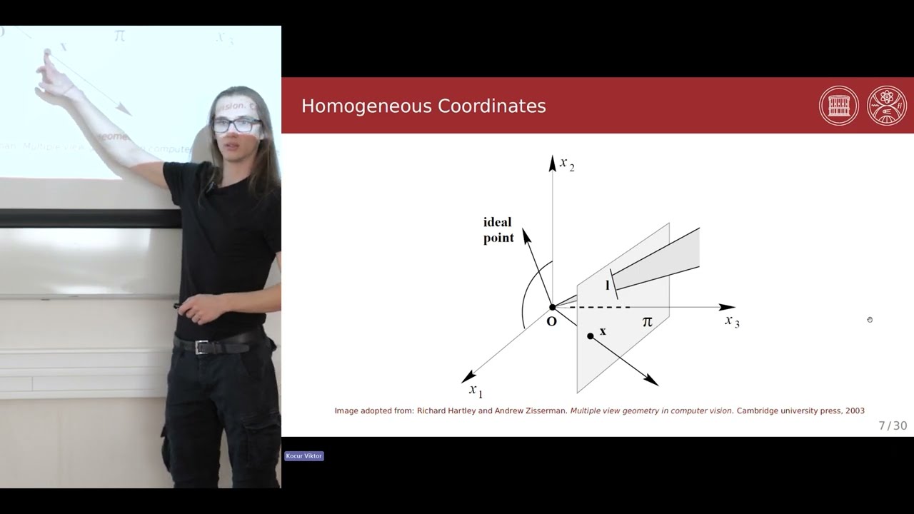
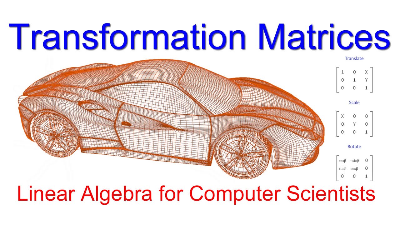
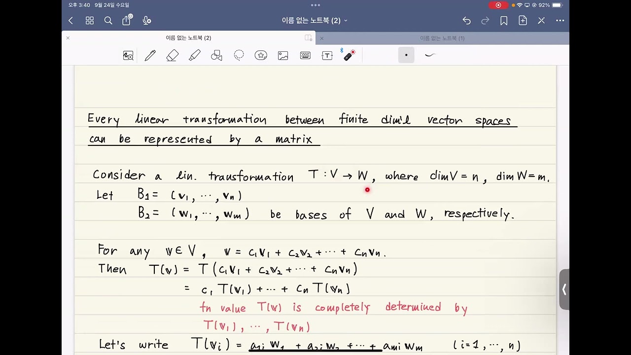
Basic linear algebra, including matrix multiplication, coordinate transformations, and homogeneous coordinates.
Advanced stereo matching algorithms, such as Semi-Global Matching (SGM) and deep-learning-based disparity estimation.
Point cloud generation and post-processing using libraries like Open3D or Point Cloud Library (PCL).
Visual SLAM (Simultaneous Localization and Mapping) using stereo camera setups for real-time robot localization.
Integration of depth maps with LiDAR or IMU data (Sensor Fusion) for autonomous vehicle navigation.
86.1K views1.6Klikes23:05Original Release: 2020-11-03
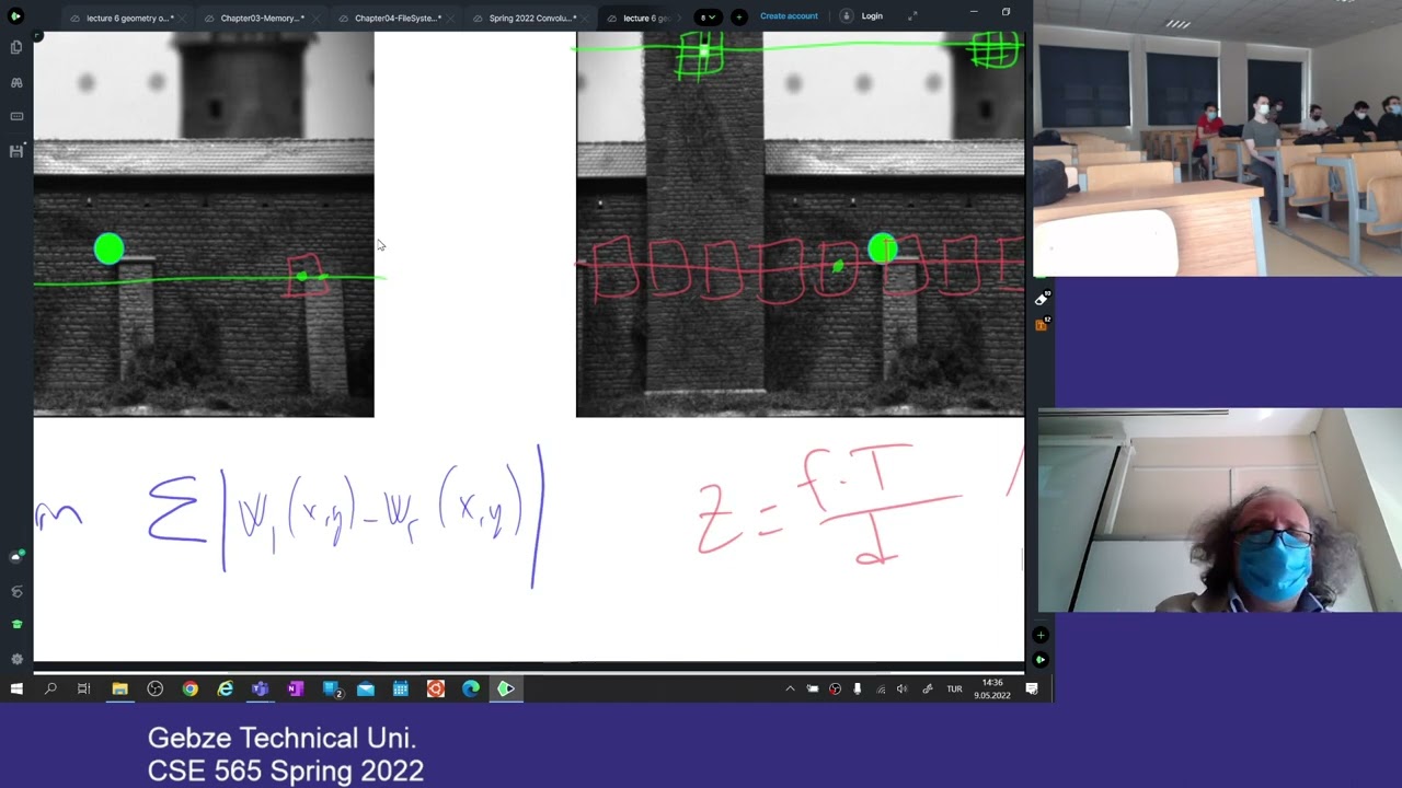
hey guys i want some new video in this computer vision tutorial in this video we're going to talk about multi-view geometry and stereo vision uh beforehand we only have one camera and but in stereo vision we have two cameras so we don't have two two dimensions anymore like we can try to estimate the depth or like distances to objects when we're using stabilization so in termination we just have two cameras that is looking at the same in the same direction or like at the same point and then we can try to estimate the depth um for those two images so let's first talk about or and get a an overview or what stable vision is so when we're using stereo vision we're reconstructing uh the 3d geometry based on camera images for uh from two or more viewpoints so we can compare this derivation to the human vision where we have uh we have two eyes that um that are looking in front of us and then if we close one of the eyes like we're having a more difficult time trying to estimate uh the depth of of the objects or like trying to estimate the distances to to an object that we see so stereo vision is like the the human vision where we have these uh two eyes or like two cameras that is that is seeing the same things and then we can use the two um individual viewpoints to try to estimate the depth or distances to objects so down here we can see the different kind of examples is where we have uh some cameras that is taking that's that that takes like images from multiple uh viewpoints and then we can have like a depth map as we can see here to the right like we have this image here and then we're trying to estimate the depth in this image here for uh from two camera images or like multiple viewpoints and then we have and then we can calculate like the disparity uh and like the disparity uh after two images and then we can get like a depth map so we're reconstructing 3d geometry and we have then have it like a three-dimensional image compared to if we only use one camera we only have two dimensions which is the x y or like the point and where the object is in the image so how how can we estimate the distance using a stereo vision so first of all as we talked about in one of the previous videos we we first of all we need to calibrate the cameras so we're going to get the intrinsic and instructing parameters from the camera calibration and i've made a video about that if you want to go more into about how to to calibrate a camera and also i showed you and i showed you a practical example of how we can actually like calibrate the cameras and get these intrinsic and extrinsic parameters for for our camera so first of all we're going to calibrate the camera so so we remove as much distortion as possible and then we can create an epipolar scheme using apollo geometry and which we're going to talk about in this video and how how we can use those to like build a disparity map and then from a disparity map how can we how can we convert that to a depth map and then we can actually like get the depth or like the distance to each point in in our image so the demand will be combined with an optical detection algorithm and like in if we're for example here down here we have a monocle our vision which is only one camera so if we're running an obstacle detection algorithm on it like we can only detect that there's a person person at this point here in the image or like an at this yeah at this point in the image but if we're using stereo vision with two cameras then we can actually like run at an obstacle detection algorithm together with our depth map and then we can actually like estimate the distance or the depth to um to a point or like in this case up to the person here in the image and then we get this the three-dimensional reconstruction of off what the camera sees instead of just like the molecular vision here where we can only like see where the person is but not like the distance to a person so severe vision can be used for a lot of practical uh different kind of examples and it's it's often used in for example like autonomous cars and and all of the different kind of stuff of dove of practical setups so another like um another example of like how we can calculate or like estimate depth and with only like one camera it could be like we could have a time-of-flight camera and the time-of-flight camera has like as an infrared and an infrared emitter that sends out infrared light and then it hits an object and then it can detect that that the camera can detect that infrared light that is and it has like emitted so it is estimated the distance by measuring the time of flight of a light signal between the camera and the subject for each point in the image so it will send out a signal here from the infrared and infrared emitter here and then and when it hits an optic it will it will be reflected back again here to the camera sensor and then by like by calculating or like because then we know like the disparity here of the of the waves or like the signals that comes back um so it will be like the difference between those signals and then we also have like the the we because we know the the the speed of light and like the frequency of the signal we're sending out and then we can actually like calculate or like estimate the depth by using this infrared light together with the camera so we don't need two cameras and if we were not on to that or if it wasn't possible to use two cameras then we would also do it but um with this time-of-flight camera here this is just another example where here we could have an image here which is like the depth estimation of an image and then we could use that for some other calculations or estimating the depth and during optic detections as well so another approach here and one of the more used ones in in like a real world practical example is actually like a microsoft uh connect connect to so this is like the sensor that is used for um for the xbox which has this infrared projector that we just talked about and then it just has um has a normal rgb camera and then the infrared camera here as i just showed you on on the previous slide so the microsoft connect here it sends out this infrared light here to try to like estimate the depth of the obstacles or like the points in the image and then it also just has this normal camera here that can be combined with the with the time of flight camera here so over here to the right we can see that we actually like have the camera and then we have the infrared projector um or like the infrared lights that get emitted out in the room and then the infrared camera it detects all those lights that that's get reflected back and then when you combine like the normal camera here and the infrared camera then we can actually like have this uh 3d construction here where we have like some some person here in the foreground and some furniture in the background here and then we can then we actually like have the depth in our image with only like a microsoft connect and we don't need uh two cameras so this is a really like a very like used loose use center in in like the in the practical world as well because it's both like relatively cheap and it does it does its purpose and we don't need like for example two two expensive cameras so we have this tags on me of uh like how we can optical like 3d acquisition method like how we can actually like reconstruct a 3d um 3d three-dimensional um view of our image so we can have this divided into passive and active where we're going to mostly focus on the passive one here with the stereo vision like how we can use two cameras to to use uh to have this frequency 3d acquisition method and the other which was like an active one with the time of flight camera and one shot structure light and also like some other multi-pattern structure light so you can think of the active acquisition method where like we have to do something active to get the information where in the passive here we just have two cameras sitting and observation observating observating what what happens what happens in like the frame or in the image where the active one we actually like have to send out infrared light and then detect it so so this will be like an active sensor where over here we have the passive sensor which we're going to to to mostly focus on in this video so just to like recap shortly which we're also going to use a bit in this video with with the camera geometry of the pinhole model so with the pinhole model we have this we have this pinhole here where all the lights from like the real world get reflected through and then like it it's all it gets here in the pinhole here so and then it will like be reflected here in the image plane inside of our camera so this will be like a pinhole of the camera and this will be the image plane that our our actual lights get reflected too and then we have this focal length here which is the length from the pinhole to the image plane which are like image or like the points from the real world get protected to our image plane so then we can set up like this pinhole um model matrix here where we have the focal length here um for the x and y direction often they're just equal to each other and then we have this vector here which is the u v which is uh which is the point on the image plane and then we can like project the world coordinates here so this in this case here this will be the tree here so the xyz coordinates here will be the tree in the image here and then we can project that until our image plane again with this matrix here and multiply that with our volt coordinates so we're going to use this um [Music] later on in the video and then we have this camera calibration here as i talked about in one of the previous videos where first of all we're converting a 3d point in the world to a 2d pixel so we have this conversion from 3d world to our our camera and then we're going to use that for our camera calibration and then we use these multiple images here to do the actual calibration and we need to do with a known object and we need to rotate around with different positions and tilt and translate it around and then we after that when we're done all that we compute the camera matrix and the distortion parameters and then we can remove the distortion and then our camera is calibrated i'm going way more in depth with all these steps and how we can actually do it and i'm i'm showing you an an example of in opencv like how we can actually do camel calibration in um in one of the previous videos so you can go check that out if you want to or or else i'll just continue in this one so in this example here when we have an exterior vision we need to calibrate both of our cameras and these are just like the different kind of distortion parameters like we could have some barrel distortion or confusion distortion tangential distortion and then when we do a camera calibration we have for example battery distortion and then we do our camera calibration and then we can translate our our original image or like a camera to to an undistorted image or like a calibrated camera and then these curved lines here will actually like be straight lines and it's easier to apply our our algorithms on the undistorted image here so when we're doing camera calibration we're going from real world coordinates to camera coordinates first so we're getting these intrinsic parameters where we're rotating like we have a rotation matrix and a translation matrix and we have to apply those to get from from like the the world coordinates to the camera coordinates which we talked about in in the pinhole model and then when we have the camera coordinates we can we can go from the actual like camera coordinates to the pixel corners that we want to get in our image and these are the intrinsic parameters here where we have the intrinsic matrix where we need the focal length and the optical center as we talked about in the printhole and model as well so here we have like the actual like matrices set up here so this will be the world coordinates here and then we apply the intrinsic parameters here and an extrinsic parameters here and then we can have like some projection match matrix here that can actually like get here we have the pixel coordinates uh q subscript uh sub sub i and then we just apply all of these uh like we convert from wall corners to camera coordinates and then from camera camera current is the pixel coordinates and then we have this projection matrix here where we can project uh real uh points in in in the real world to uh to image points or like pixel coordinates in in our in our image so when we're talking about stereo vision we have this multiview geometry so we have a camera here to the left and one camera here to the right and the need to be aligned on the same x and y axis so it is like so so we can so we able to use this derivation so the only like the only difference of the two cameras is is the c which is the depth um or we just like the depth or like the z and that is used for estimating the depth and so we have this left and right camera here where they are aligned to each other and we just try to estimate the depth um with the z-axis so if we take a look from the part of this example here like if we look from above like we can use some of the geometry for for the stereo vision and here we look at top here and then we have like some point here we see in the image for both cameras so the left camera here will be this triangle and will be this triangle here and then we can set up some some formulas try trying to like estimate um the c here or like the disparity here from the optical center of our camera here to the line that goes um through like to the point here we see in the image and then we can do the same here for the right camera um which has the optical center here and then we can calculate like this this uh like this distance here from the optical sender um to the line that goes to the point here we see in the camera frame and then first of all we can just set up some some equations here where we can see like this xl here so the distance from the obstacle center to the line here can be calculated by newton by knowing this x here so this is like um the like the x here and then we have have the c which is the distance from the camera to like the point we see and then we have the f here which is the focal length and then we can set up the same formula here for the x um x subscript r and then we have these two formulas here and we can actually like calculate this disparity of of um of like the the gamma through here so this disparity in this case here will be x subscript l minus x subscript r so it will be this distance here minus this distance here and then we can like have this disparity map instead of a disparity map and then when we have a disparity map we can actually like convert that to a depth map so when we have like the disparity in dead maps here like the disparity is the difference in the image location of the same 3d point from two different camera angles so this is what i just showed you here like we have these disparities here um which is like the difference in the image location so it will be this this distance here and then we can like um if we have it like a pair of images then you can actually like measure the apparent motion and pixels for every point and make an intensity image from the measurement so when we have this image here and we get multiple views from it um we can calculate the disparity and then afterwards we can actually like calculate the depth map so here we have this disparity here as we as we calculated on the previous slide with one of the formulas and these x and y here will just be like the points in the image here so we also already know that and then we have this b here which you also knew from one of the formulas from the previous slide and also the focal length of our camera and then we can actually like calculate the c value here which is the depth or like our estimation of the depth in the image and then from that formula here we can actually like set up this image here to the right where we can see the depth of the images so we can see the lamp here is is more wide than like the the more the more back in the background like the optics are like the more dark or like great they get because they're getting further away from the camera so we have this um when we have this that map and the disparity map we can actually like use something called applicable archaeometry and what this means is that we're given a point in one of the cameras and then the corresponding point in the other camera lies on the ever poly line so we can see here that we that we like uh have a point here in the camera uh image here or in the left camera and then the corresponding point in the other camera it lies on every parallel line so this red line here will be the ever pilar line for the right camera here and then these points here that we can see from this image like from this camera here are these points here and they can be projected down to this april line here on the right on the right camera frame here or like image frame and then we have a seven degree freedom fundamental matrix that we can then set up and then we can find over here to the right we can see that we have some points here in one of the images and then we have these every out lines here um which is corresponding to the point here from the from one of the cameras and then we can actually like um use that to estimate the depth of the cameras and by only on by only having one point in one camera and then we can just search for all the points in on the apple our point uh or on the ebola line in the other image so we have this stereo corresponds problem and like how can we solve it and compute the disparity so to solve it and and and like try to estimate uh the the disparity is that we first take a pixel in the left image as i talked about and then we have the left image here and then we search on the epipolar line for that pixel in the right image so it will be the red line here so this will be only a one dimensional search because the point we know that the point is located on the epipolar line and then we just need to search and search through that line for the point and then we can like as i feel like estimate where that point is in the right image frame and that but we have one constraint here and it is that the cameras need to be aligned along the same axis um because then you only have this one dimension and we can just search and it will align where this point is in the image so every search and images if we're going to like uh trying to implement it then we need to take each pixel on the line in the left image so we have like for example and a line here and then we say each pixel of those lines here and then we compare the left image pixels to the right in those pixels on the same on the same impulse line so this line here will be the every pro line on the right image and we just compare all these pixels to each other and then we take the pixel with the minimum cost which will be which will be around here and then we can compute the disparity of the image here which will be around here um with the blue here where we have an error pointing here so this will be the disparity here when we're doing april search on this image and everybody search on this line here in this image so and a practical example of like how we can use stereo vision and as we've been over like how we can detect objects in in an image and try to estimate the adapter so first we calibrate the cameras and one like the images that we're going to um to try to estimate the depth on and then we have the image image parameters for both images or like the cameras that we can then um apply it together with some of the other steps that we've talked about in this video and then we have the example down here we have a lift image or like a left camera that sees uh this image here and the right camera that sees this image here and then we can see like the person here is a bit further in front and compared to the to the left image here it also makes sense and then we just need to like calculate the disparity from these two maps here and then we can convert that disparity map to a dipmap and then we have the depth compare combined with it and an obstacle the taking algorithm and then we have this three dimensional so when we need to compute the disparity maps here we first we need to determine the disparity between the two images and then after that we can decompose the projection into the camera matrix both for the intrinsic and extrinsic parameters so like to decompose um the projection into a camera matrix we can just use the built-in function in opencv to do that and then after that we can estimate the depth by using the information from the last steps so left down here we have this disparity map here and on the right we have the disparity map for the right image here and then we can use these two disparity maps here and and try to estimate a depth map from those so to create a depth map we use this projection matrix as i just talked about for each of the cameras and then we we can either like just apply that in in a function in opencv and then we can take take the focal length out of the camera matrix and then we also like can compute the baseline using corresponding values from the translation vectors and so the more of the intrinsic parameters but we can also like have the baseline if we knew how far um the cameras were placed from each other and then we can compute the depth map of the images from the disparity maps with with these foam layers that i showed you down here before so the most interesting one is to see here um so we have this focal length here that we got from our camera matrix that calibrated and then we have the b parameter here and the disparity as we calculated on the last map so then we're using this sparing map or like the disparity for each pixels in the two um two immature images here and then we can actually like apply this formula here and then we will get a depth map for each of the images so the left here we have the depth map of the left image and here we have the depth map of the right image and then we can use those to to just take a point um in the depth mat here and then we will get the actual like distance or depth to an object in or like an object or a pixel in the frame so the result of this um that definition here is that we can either like run an obstacle detection algorithm and use it together with a dead map so in this case here we're detecting a car and a car around here and then we try to estimate the distance or the depth to that car so right now we have the dead knife here like we know the distance to every single point in the image from the devnet and then we can just take the closest point of the detected obstacle so we're running some optical detection algorithm and then it will um make this boundary box around it and then we can just take like the closest point of that obstacle um because we know all the distances from every single point and then we can combine that and we will get like the x x and y um and x and y positions in the image from our obstacle detection algorithm and then from our depth map or like our depth estimation we will get the distance to it so we'll actually like have a an x and y and a c coordinate so we have this 3d reconstruction of an image by using stereo reason compared to only a monocle our vision where we only have um we only have one camera and we can only have this two-dimensional um view of the of the world because we can only have the x and y where when using stereo vision we can calculate or estimate the depth in the image as well so we have this freaking 3d image so thank you guys for watching this video and remember to subscribe button and notification on the video and also like this video if you like the content and you want more of in the future i'm calling out during an algorithmic data structures tool and an artificial intelligence tutorial in simples plus um where we're talking about reinforcement learning and stuff like that so if you're interested in one of those i'll link to one of them up here or else i'll just see in the next video guys bye for now [Music]
Up Next
27:30
Depth Estimation with Stereo Vision in Python and OpenCV
@NicolaiAI
45.2K views•2021-02-04

87:26
Introduction to Secure Multiparty Computation with Yehuda Lindell
@fhe_org
7.7K views•2021-02-04
28:48
Camera Calibration with OpenCV Python | Computer Vision Tutorial
@NicolaiAI
110.2K views•2021-03-28
19:25
Enigma Machine Mechanics: WWII Encryption Explained
@JaredOwen
13.2M views•2021-12-11
Related Study Plans & Knowledge Roadmaps
Structured learning paths in Computer Science
computer-science
Container Runtimes: Namespaces, Cgroups & Go
01Linux Systems & Go Programming Foundations
02The Core of Isolation: Chroot and Filesystems
03Linux Namespaces: Process Isolation
+ 3 more learning modules
32h6 modules
Explore Roadmap
computer-science
Building a CHIP-8 Emulator: Rust & CPU Basics
01Computer Architecture Foundations (Bits & Bytes)
02Rust Programming for Systems Development
03CHIP-8 Virtual Hardware Specifications
+ 2 more learning modules
32h5 modules
Explore Roadmap
computer-science
Building BitTorrent: Go, P2P & Concurrency
01Go Fundamentals & Concurrency
02Networking Foundations & P2P Architecture
03Bencode Parsing & Torrent Metadata
+ 3 more learning modules
26h6 modules
Explore Roadmap
computer-science
Actor Models (C++ Concurrency & Lock-Free)
01C++ Multi-Threading Foundations
02Thread Pools and Task Scheduling
03Atomics and Lock-Free Queue Design
+ 3 more learning modules
45h6 modules
Explore Roadmap