Brushless motors are superior to traditional DC motors for underwater applications because they lack exposed brushes that can short circuit when exposed to water, allowing them to operate indefinitely underwater without electrical failure.
Brushless vs Brushed RC Motors: Key Differences Explained
Added:Deep Dive
Basic principles of electromagnetism, including how electric currents generate magnetic fields to produce mechanical motion.

VIDEO AULA 8 - MAGNETISMO E ELETROMAGNETISMO - Curso Eletricidade Básica
41.4K
Electric current flowing through a conductor generates a magnetic field around it, establishing the fundamental principle of electromagnetism. The field strength increases proportionally with current and number of coil turns. An electromagnet is created by wrapping wire around a ferromagnetic core and passing current through it. When current flows, the core becomes magnetized and attracts ferromagnetic objects; when current stops, magnetism disappears. This principle underlies all electromagnetic devices from small relays to large industrial equipment.
Click to watch →

ncert||science||std10||chap13||વિદ્યુતપ્રવાહની ચુંબકીય અસર ||part2
109
This comprehensive section covers the complete principles of electromagnetism. Electric current flowing through conductors generates magnetic fields forming concentric circles around the wire. The right-hand rule determines field direction: thumb points with current, fingers curl in field direction. When current-carrying conductors are placed in external magnetic fields, they experience forces perpendicular to both current and field directions. Fleming's Left-Hand Rule determines force direction: thumb (force), forefinger (magnetic field), middle finger (current) must be mutually perpendicular. Electric motors convert electrical energy to mechanical motion using these principles, with commutators reversing current every half-turn for continuous rotation. Electromagnets consist of coils wrapped around soft iron cores, producing magnetic fields only when current flows. Field strength increases with more coil turns, higher current, or stronger core materials. These principles power household appliances like washing machines and mixers.
Click to watch →

Warum dreht sich ein Elektromotor WIRKLICH Was hinter jeder Bewegung steckt Feynman erklärt
253
Electric current and magnetism are unified phenomena, not separate forces. Hans Christian Oersted discovered in 1820 that current-carrying wires deflect compass needles, proving electricity produces magnetism. Michael Faraday later showed changing magnetic fields induce electric current. James Clerk Maxwell synthesized these discoveries into four equations, revealing electricity and magnetism as aspects of a single electromagnetic field. When current flows through a conductor in a magnetic field, the Lorentz force pushes the conductor perpendicular to both current and field directions. This fundamental principle underlies all electric motors.
Click to watch →
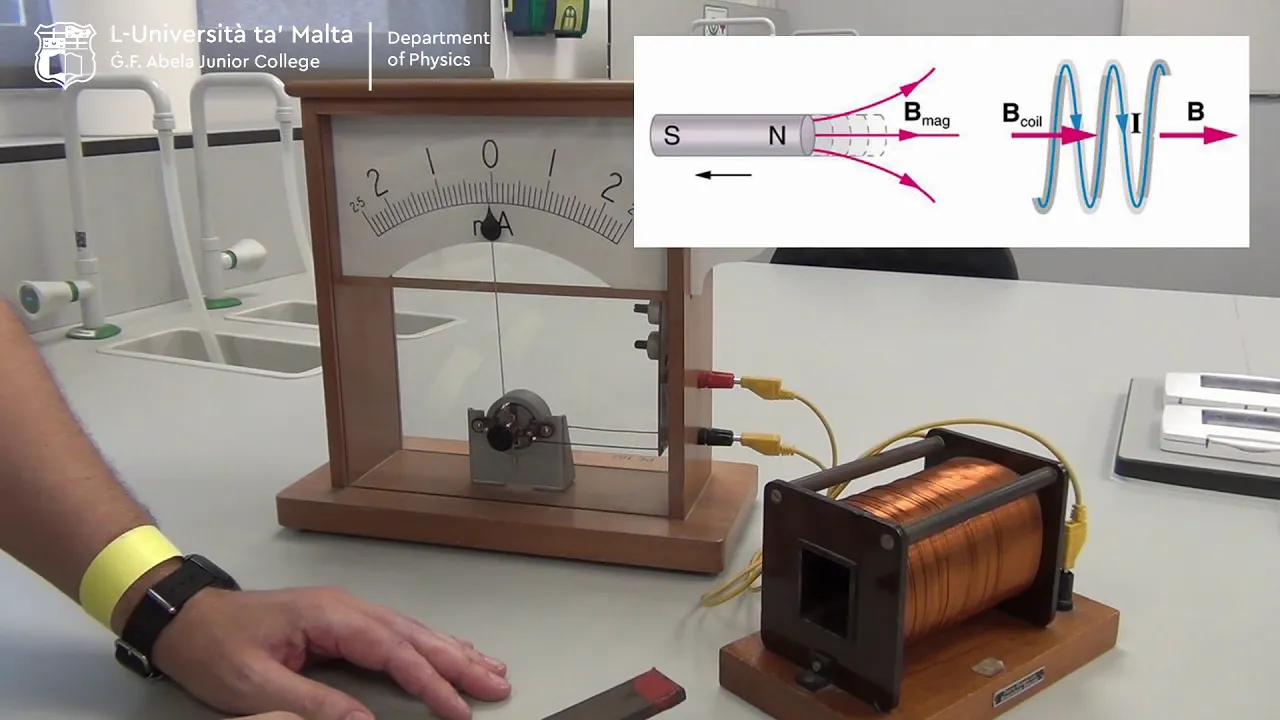
Electromagnetism, Magnetism and Static Electricity
924
This segment covers three interconnected electromagnetic principles. First, electric current generates magnetic fields, demonstrated by compass needles deflecting when placed near a current-carrying wire. Second, coiled wires produce organized magnetic field patterns visible through iron filings alignment. Third, current-carrying loops in magnetic fields experience rotational forces, forming the basis of DC motors. These experiments establish that electricity and magnetism are fundamentally linked phenomena, where moving charges create magnetic effects that can produce mechanical motion.
Click to watch →

Hora da Verdade EAM: Física com Prof. Fulconi
2.6K
This section covers electromagnetism principles: Oersted's discovery that current produces magnetic fields, Ampere's study of forces between current-carrying wires, and the behavior of electromagnets. Students learn that like poles repel and opposite poles attract, understand how magnetic field lines form closed loops, and learn how electric motors use electromagnets to create mechanical motion.
Click to watch →
Deep Dive
Fundamental electrical concepts such as voltage, direct current (DC), resistance, and power (Watts).
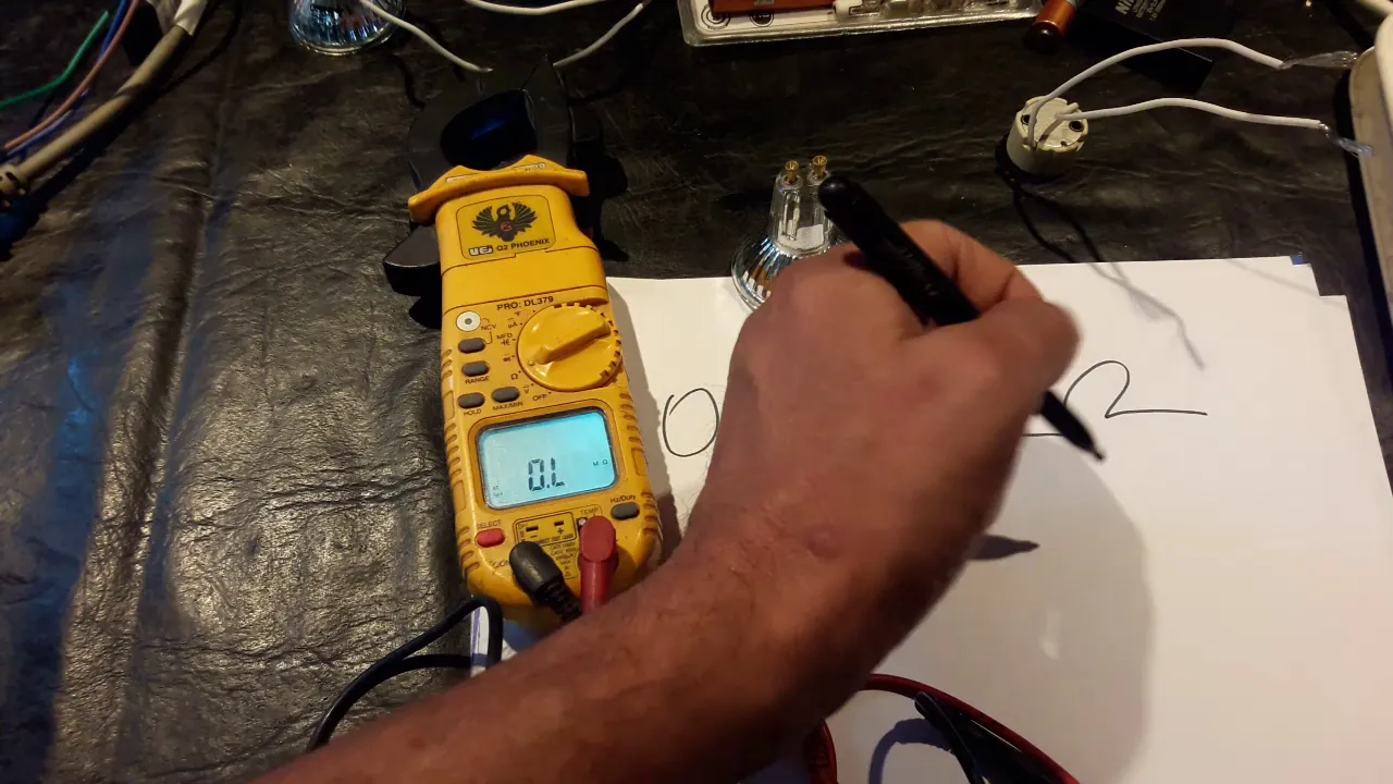
Electricidad, conceptos basicos
2K
The four fundamental electrical concepts are: (1) Tension/Voltage measured in volts, (2) Current measured in amperes, (3) Electrical Resistance measured in ohms, and (4) Power measured in watts. There are two types of voltage: Continuous Voltage (DC) found in batteries with positive and negative terminals, and Alternating Voltage (AC) found in household outlets that reverses direction periodically. Standard household voltage is typically 220V, though actual values may vary between 200-230V. Electrical resistance is the opposition to current flow, measured in ohms. Components with higher power ratings have lower resistance, while components with lower power ratings have higher resistance. For example, a 50W lamp has approximately 76 ohms of resistance, while a 300W lamp has approximately 9 ohms. This inverse relationship exists because higher power devices need to allow more current to flow through them to produce more energy output.
Click to watch →

masterclass todo en electronica en una sola clase
69.4K
Voltage is the electrical force that pushes electrons through a conductor, measured in volts. Current is the flow of electrons through a conductor, measured in amperes. Resistance is the opposition to electron flow offered by a material, measured in ohms. Power is the rate at which electrical energy is consumed or dissipated, measured in watts. These four concepts form the foundation of all electrical and electronic circuits.
Click to watch →

MÓDULO 1 : Principios de la electricidad
147
This comprehensive section covers the four basic electrical concepts: voltage, current, resistance, and power. Voltage is defined as the difference of potential between two points, measured in volts (V) with kilovolts (kV) for higher values. DC voltage has constant value and fixed polarity, while AC voltage varies sinusoidally with changing polarity. The RMS value (e.g., 220V) represents equivalent DC heating effect, with actual peak voltage higher (311V for 220V RMS). Current is the flow of electrical charges, measured in amperes (A), with DC flowing in one direction and AC varying periodically. Resistance opposes current flow, measured in ohms (Ω), depending on material, cross-sectional area, and length. Power is calculated as P = V × I, measured in watts (W) with kilowatts (kW) for higher values. Electrical energy consumption is E = P × t, measured in kilowatt-hours (kWh) on electricity bills. Ohm's Law establishes the relationship between voltage, current, and resistance: V = I × R, which can be rearranged to solve for any variable.
Click to watch →

Voltage, Current, Resistance and Power Explain!
175
Electronics is the study of controlling electrons, which power everything from toys to spaceships. Atoms contain electrons, and electricity is the flow of these electrons between atoms. Voltage is the pressure that pushes electrons through a circuit, measured in volts (AA battery: 1.5V, wall outlet: 120V). Current is the flow of electrons, measured in amps (light bulb: milliamps, oven: several amps). Resistance is opposition to current flow, measured in ohms (copper: low resistance, rubber: high resistance). Power is the rate of energy consumption, measured in watts (100W bulb uses more energy than 60W). These four concepts are related by Ohm's Law: current is directly proportional to voltage and inversely proportional to resistance.
Click to watch →

D'Amore Engineering University Series: Video 1 Basic DC Electricity
11.8K
Direct Current (DC) is the most basic form of electricity. Voltage (V) is the electrical push or force measured in volts, named after Alessandro Volta. Current (I or A) is the flow of electrons measured in amps, named after André Ampère. Resistance (Ω) is the opposition to electron flow measured in ohms, named after Georg Ohm. Power (W) is the rate of energy transfer measured in watts, named after James Watt. These four quantities form the foundation of DC circuit analysis.
Click to watch →
Deep Dive
An introductory understanding of basic DC motor components, specifically the roles of a stator, rotor, and electrical contacts.

MOTOR DC
15.6K
A DC motor consists of three main components: the stator (stationary part with permanent magnets), the rotor (rotating part with coils and commutator), and brushes (stationary contacts). The stator includes an outer casing, two permanent magnets with opposite polarities facing each other, and serves as the structural support. The rotor contains an axle, coils wound around a ferromagnetic core, and commutator segments (delgas) that are electrically isolated from each other. Brushes maintain electrical contact with the rotating commutator. The stator frame is constructed from plywood pieces, wooden dowels, and permanent magnets placed at marked positions with opposite polarities facing each other.
Click to watch →
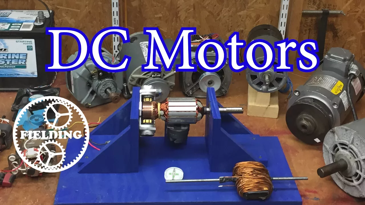
How Motors Work For Beginners (Episode 1): The DC Motor: 032
2.6M
A permanent magnet DC motor consists of two main components: the stator and the rotor. The stator is the stationary part containing permanent magnets that create the magnetic field. The rotor is the rotating component that contains coils of wire wound around laminated iron plates. In some motor designs, the permanent magnets can be mounted on the rotor while the windings are on the stator, which is the configuration used in brushless DC motors.
Click to watch →

Wir BAUEN das PUZZLE zusammen! (Schrauben mit Patrick)
55.6K
A DC motor consists of a stator (stationary part) and a rotor (rotating part). The stator contains the magnetic poles (north and south) that create the magnetic field. The rotor, also called the armature, contains the windings that carry the electrical current. When current flows through the rotor windings, it interacts with the magnetic field from the stator, creating a force that causes rotation.
Click to watch →

How does an Electric Motor work? DC Motor explained
1.3M
A DC motor converts electrical energy into mechanical energy. The main components include: (1) Stator - the metal protective casing containing permanent magnets that form north and south poles; (2) Shaft - a central rod used to transfer mechanical energy; (3) Rotor - made from laminated iron disks with T-shaped arms where coils are wound; (4) Commutator - a segmented copper ring mounted on the shaft with electrically isolated plates; (5) Brushes - conductive materials that rub against commutator segments to complete the circuit; (6) Terminals - connection points for the power supply. The rotor coils and commutator rotate while other components remain stationary.
Click to watch →

महा मैराथन Energy Conservation (EC) 4th Semester बस इतना पढ़ लो हो जाओगे 100% पास | JE CLASSES Meerut
45.3K
A DC motor consists of: Yoke/Frame (mechanical support), Stator (stationary part with field windings), Rotor/Armature (rotating part with armature windings), Commutator (converts AC to DC), and Brushes (collect current from commutator). The motor works on Fleming's Left Hand Rule. Stator components include pole shoes with field windings, counter-shank screws for stability, and uniform air gap for consistent flux. Rotor components include armature core (silicon steel), armature windings, shaft, and commutator segments with mica insulation. The commutator converts AC to DC and is made of hardened copper. Brushes are sliding contacts that collect current from the rotating commutator.
Click to watch →
Deep Dive
A general familiarity with RC (Radio Control) power systems, including the basic relationship between the battery, speed controller, and motor.

🤖Beginners Guide to Making Radio Control Vehicles and Robots, with James Bruton!
37.1K
RC power systems require understanding three interconnected components: batteries, electronic speed controllers (ESCs), and motors. Batteries use 'S' (series) and 'P' (parallel) designations to indicate internal cell configuration - a 6S battery provides approximately 22-25 volts. The milliamp hour (mAh) rating indicates capacity, while the C rating specifies maximum continuous current draw as a multiple of capacity. ESCs manage high-current power delivery, with two main types: speed controllers maintaining target speed by drawing whatever current is needed, and current controllers limiting maximum current regardless of load. Brushless motors are categorized into outrunner (high torque, external magnets) and inrunner (rotating magnets inside coils) designs, with KV ratings indicating RPM per volt applied. Proper component matching ensures safe and efficient RC vehicle operation.
Click to watch →
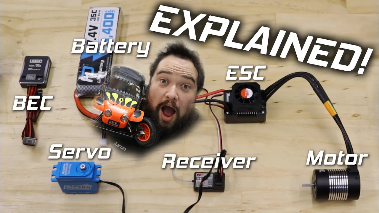
How does an RC car work? Hobby Electronics Explained for Beginners!
722.8K
RC car power systems consist of interconnected components: batteries provide stored electrical energy, ESCs regulate power distribution, and motors convert electricity into mechanical motion. Batteries are characterized by voltage (determining speed) and capacity (determining runtime). ESCs control motor speed by regulating power transfer and may include programmable features. Brushless motors use KV ratings (RPM per volt), while brushed motors use turn counts. Motor direction can be reversed by swapping wires. This integrated system enables precise vehicle control through electronic management of electrical power.
Click to watch →

How Do I Properly Wire An RC ESC, Motor, And Battery? - RC Toy Central
104
An RC vehicle's power system consists of three main components: the battery (which supplies power), the electronic speed controller (ESC) (which manages the motor's speed), and the motor (which moves the vehicle). The ESC acts as the link between the battery and the motor, translating signals from the remote control into movement.
Click to watch →

Introduction to Fixed Wing electric power systems for newbies.
9.2K
This section covers the three core electrical concepts essential for RC power systems. Voltage (volts) represents electrical potential or pressure, analogous to water pressure in a pipe, with LiPo batteries providing 3.5-4.2 volts per cell in series configurations (3s ≈12V, 4s ≈16V). Amperage (amps) measures current flow through circuits, calculated from battery capacity (mAh) and C-rating (e.g., 1000mAh @ 10C = 10 amps). Wattage equals voltage multiplied by current, representing total power available. Understanding these relationships enables proper component matching for safe and efficient RC operation.
Click to watch →

This RC Car Gets The Adrenaline Going! Losi Hammer Rey U4 Trophy Jeep | RC Driver
53.3K
RC vehicle electronics systems include a 3150 KV 4-pole motor, a 614S metal gear waterproof high-torque servo, and a Smart 130 amp speed controller capable of handling 2S to 4S battery packs. The speed controller includes programming features for punch and brake settings. The 6200A AVC receiver provides multiple auxiliary ports. The battery compartment uses IC5 connectors and accepts standard 2S or 3S LiPo packs. A large heat sink helps dissipate motor heat in enclosed bodies. The system requires matching components from the same ecosystem for optimal performance.
Click to watch →
Prerequisite Knowledge
- Concept 01Basic principles of electromagnetism, including how electric currents generate magnetic fields to produce mechanical motion.
- Concept 02Fundamental electrical concepts such as voltage, direct current (DC), resistance, and power (Watts).
- Concept 03An introductory understanding of basic DC motor components, specifically the roles of a stator, rotor, and electrical contacts.
- Concept 04A general familiarity with RC (Radio Control) power systems, including the basic relationship between the battery, speed controller, and motor.
Subsequent Learning
- Step 01In-depth functionality of Electronic Speed Controllers (ESCs), comparing brushed ESCs to complex three-phase brushless ESCs (sensored vs. sensorless).
- Step 02Understanding motor specifications such as KV ratings, turn counts, torque curves, and how to select the right motor for specific RC applications.
- Step 03Advanced power management, including the relationship between LiPo battery C-ratings, voltage, and motor current draw.
- Step 04Thermal management, gear ratio optimization, and preventative maintenance techniques to maximize motor longevity and efficiency.
Upgrades
Motor Test
Solution
Design
Testing
Upgrades
0:00Playing Section
- 1
Incorporating viewer feedback for RC boat enhancement.
- 2
Focusing on propeller size and motor placement.
The Continued Relevance and Advantages of Brushed Motors in Specific RC Applications
While brushless motors are often framed as the ultimate upgrade due to their superior speed, efficiency, and longevity, brushed motors remain highly relevant and are often superior for specific RC disciplines. In rock crawling and trail driving, brushed motors deliver unmatched ultra-low-speed control and smoother start-up torque without the 'cogging' or stuttering common in budget-friendly sensorless brushless systems. Furthermore, brushed setups are significantly cheaper, simpler to wire, and easier to waterproof. For beginners, budget-conscious hobbyists, and specialized crawlers, brushed motors offer practical and performance advantages that high-cost brushless systems cannot easily replicate.
Deep Dive
In-depth functionality of Electronic Speed Controllers (ESCs), comparing brushed ESCs to complex three-phase brushless ESCs (sensored vs. sensorless).

Mini Z MR-04 EVO2 - Detailed look and test drive
69.8K
The MR04EVO2 features a sensored brushless ESC (Electronic Speed Controller) compared to the older EVO1's sensorless version. Sensored ESCs use Hall effect sensors to detect motor position, enabling significantly smoother throttle control and more precise power delivery. This technology allows for better throttle modulation and reduced wheel spin during acceleration, making the car more predictable and easier to control.
Click to watch →

Sensored Vs Sensorless Brushless Motors - The Difference In Action
60.3K
Sensored brushless motors use hall effect sensors to provide the ESC with precise rotor position information, enabling smooth low-speed operation and controlled acceleration; in contrast, sensorless motors rely on the ESC guessing rotor position through back EMF detection, resulting in jerky startup behavior until sufficient speed generates detectable back EMF for phase synchronization.
Click to watch →
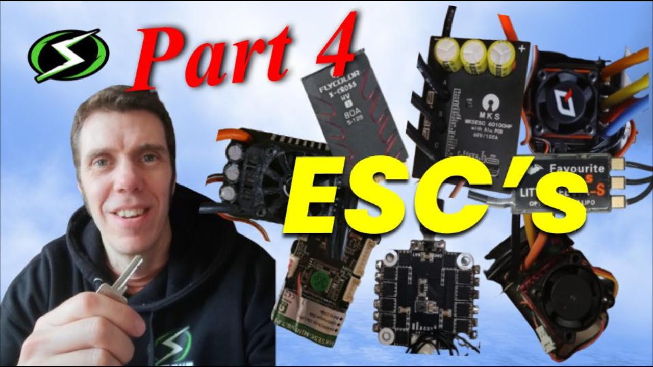
Part 4: Unlocking The Magic of ESC's!
1.2K
There are two ways for an ESC to know when to switch voltages in sync with motor rotation. In sensored configurations, a position sensor on the rotor tells the ESC its position at any time, making it easier to apply switching at the correct time but requiring additional equipment. In sensorless configurations, the ESC measures the back EMF voltage from the phase that is always not energized, and uses the point when it crosses 0 volts to trigger when to energize that phase. The sensorless method requires the motor to be turning to work.
Click to watch →

Brushed Is DEAD In 2026... Right?
9.2K
Brushless systems can be sensored or sensorless. Sensored brushless motors use three Hall effect sensors to precisely determine rotor position, allowing the ESC to deliver power to the correct coils at exactly the right moment. This provides smooth startups and precise control. Sensorless brushless systems use back EMF (electromotive force) detection to infer rotor position without physical sensors. While sensorless systems are cheaper and work adequately for most bashing situations, they have slightly worse startup performance compared to sensored systems.
Click to watch →

Brushed & Brushless ESC's differences and recommendations
1.2K
Electronic Speed Controllers (ESCs) are the most critical component for both brushed and brushless motors. ESCs control motor speed through pulse-width modulation, sending electrical pulses to electromagnets where pulse length determines speed. Higher frequency ESCs (like the Hobby Wing 1080 at 16,000 Hz vs. Traxxas XL5 at 1,700 Hz) provide finer control resolution and faster motor response. Advanced ESCs use feedback from motors to implement adaptive drag braking, sensing motor stall conditions and allowing slight overrun for smoother braking. Field Oriented Control (FOC) technology measures magnetic fields to maintain constant target RPM, automatically adjusting torque to overcome obstacles and maintain consistent speed regardless of terrain changes.
Click to watch →
Deep Dive
Understanding motor specifications such as KV ratings, turn counts, torque curves, and how to select the right motor for specific RC applications.

Understanding KV Rating in Brushless RC Motors: RPM Per Volt Explained
604.5K
Brushless motors require an Electronic Speed Controller (ESC) to convert DC battery power to AC motor power and control speed via throttle input. KV rating defines motor speed characteristics: a 1400 KV motor produces 1400 RPM per volt applied. Low KV motors (larger diameter) generate high torque for slow-speed applications, while high KV motors (smaller, thinner) achieve high RPMs for speed-focused use. Understanding KV is essential for matching motors to appropriate propellers and flight models.
Click to watch →

Relação entre Motores Brushless e Hélices para aeromodelos elétricos
38.3K
Motor KV rating indicates how many RPM the motor will produce per volt applied. For example, a 1100 KV motor will produce approximately 11,000 RPM when connected to 12 volts. Higher KV motors spin faster but produce less torque, while lower KV motors produce more torque but spin more slowly. Motor KV selection depends on aircraft weight and desired performance: high KV for speed, low KV for thrust. Using mismatched combinations (high KV with large helicopter) causes overheating and damage. Motor KV rating is fundamental to selecting appropriate motors for different RC aircraft applications.
Click to watch →
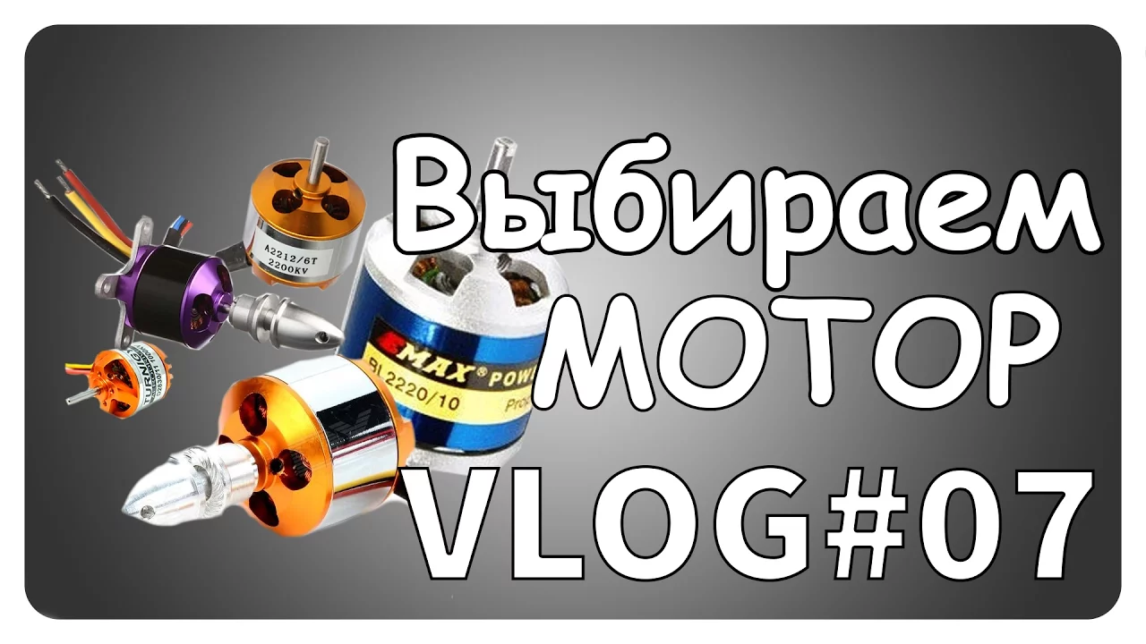
Как выбрать бесколлекторный мотор VLOG#07
77.4K
Brushless motors are more reliable than brushed motors due to the absence of carbon brushes. They contain magnets on the outer casing and internal coils activated sequentially for rotation. KV rating (RPM per volt) determines motor speed characteristics—higher KV means faster maximum speed but less torque and power. KV selection requires matching motor to application: higher KV suits racing with small propellers for quick acceleration, while lower KV provides more torque for larger propellers and load capacity. KV affects battery efficiency—excessive KV causes coil heating and wasted energy. For RC aircraft, 1400 KV motors suit models up to 500 grams, while 1000 KV enables larger 11-inch propellers. The 10T marking indicates coil type, with lower T values producing more RPM but less power.
Click to watch →

KV Comparison of Cheap & Popular A2212 Brushless Motors. Which KV For your Airplane.
172.5K
The video introduces the concept of KV ratings in brushless motors, explaining that KV represents the RPM per volt of electrical input. Higher KV motors spin faster at the same voltage but produce less torque, while lower KV motors spin slower but generate more torque. This fundamental relationship between KV rating and motor performance is essential for selecting appropriate motors for different RC aircraft applications.
Click to watch →

I Put a CRAZY Motor in this Mario Kart RC Car!
383.8K
Brushless motor KV rating indicates the motor's speed in RPM per volt. A 7,200 KV motor will spin at 7,200 RPM when powered by 1 volt. Higher KV motors spin faster but produce less torque, while lower KV motors produce more torque but spin slower. The KV rating helps match the motor to the application's speed and power requirements.
Click to watch →
Deep Dive
Advanced power management, including the relationship between LiPo battery C-ratings, voltage, and motor current draw.

LE COIN DU DEBUTANT LiPo : Les C, mAh, taux de décharge, chauffe moteur, vario ce qu'il faut savoir
19.4K
In RC systems, the motor is the primary consumer that determines current requirements, and the battery's C-rating must match or exceed the motor's continuous current draw to prevent overheating and damage to the battery, variator, and motor; the variator regulates current flow from battery to motor but does not force current into the system.
Click to watch →
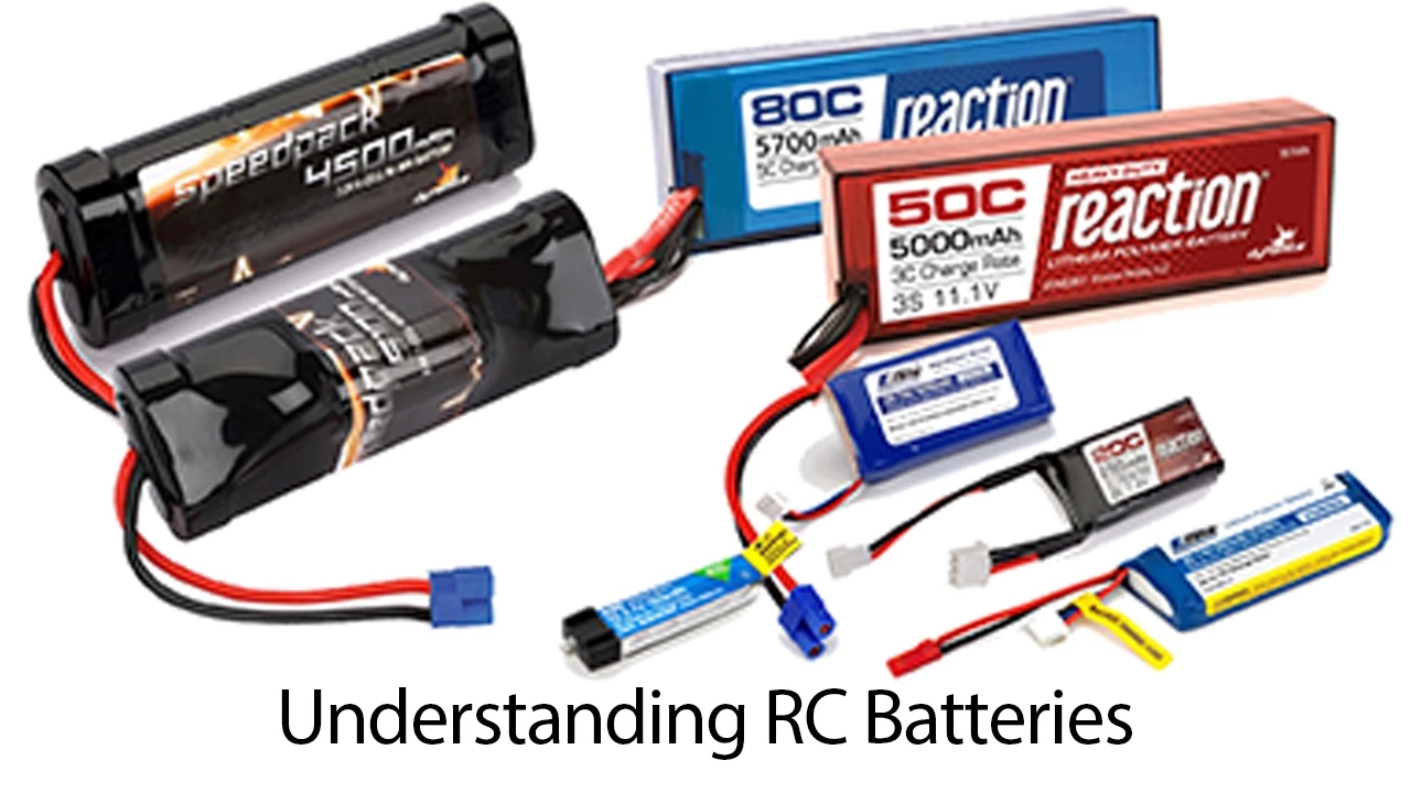
Understanding RC Batteries By Horizon Hobby
808K
C rating measures maximum continuous current a battery can safely deliver or accept, critical for LiPo batteries. Higher C ratings enable larger props, motors, and gearing without damage. Charge rate C ratings allow faster charging—3C enables 15A for 5,000mAh batteries versus standard 5A. Always use LiPo safety bags and never leave charging unattended. Follow manufacturer ratings strictly—never undershoot recommended C ratings. Higher charge rates slightly reduce lifespan but accelerate hobbyist enjoyment. The water pipe analogy illustrates current flow: higher C ratings allow more current through like wider pipes. Proper battery management balances performance, safety, and longevity in RC applications.
Click to watch →

LiPo | 3 choses essentielles à connaître
5.3K
LiPo batteries consist of cells connected in series, where 'S' indicates cell count (2S=2 cells, 3S=3 cells). Each cell has a nominal voltage of 3.7V, reaching 4.2V when fully charged. Total voltage equals the sum of individual cell voltages (3S nominal=11.1V, full charge=12.6V). Critical safety limits: never exceed 4.2V per cell (explosion risk) or drop below 3V per cell (unrechargeable). mAh indicates capacity—higher mAh means longer runtime at the same current draw. C-rating measures current delivery capability: a 50C battery can deliver 50 times its capacity (1000mAh at 50C=50A). Higher C-ratings allow more current flow, similar to larger tube diameters. System reliability depends on the weakest component (ESC, motor, receiver, battery).
Click to watch →
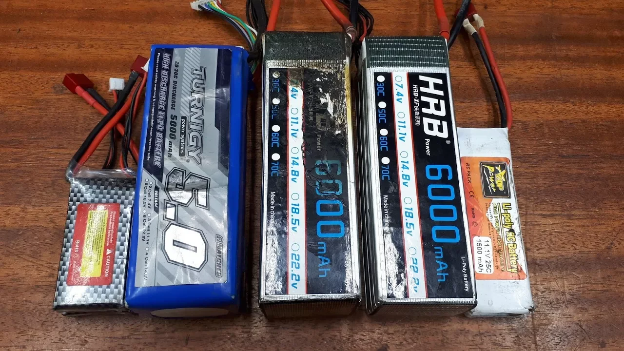
Почему вздуваются LiPo аккумуляторы - мой опыт иногда плачевный
246K
LiPo batteries differ fundamentally from Li-ion batteries in their discharge capabilities. LiPo batteries can deliver extremely high currents, discharging in 3-5 minutes compared to the 1+ hour required for Li-ion batteries. A 1500mAh battery can deliver 18 amps for 5 minutes. The C-rate indicates peak current capability relative to capacity (e.g., 25C means 37.5 amps). Battery voltage depends on cell count: 2-cell = 8.4V, 3-cell = 12.6V, 6-cell = 25.2V. Each cell has critical voltage limits: maximum 4.2V for charging, minimum 3.0V for discharge. Exceeding these limits causes swelling in 90% of cases.
Click to watch →

Here's why you NEED to Buy the HIGHEST C Rating Battery - LiPo
20.5K
The C rating of a lithium polymer battery determines its maximum continuous discharge current capacity. Calculated by multiplying the C rating by battery capacity in amp hours, higher C ratings enable greater current delivery. While motors only draw what they need, higher C ratings provide three key benefits: improved voltage stability under load for marginal power gains during acceleration, reduced operating temperatures enabling longer performance duration, and enhanced battery lifespan through decreased thermal stress. These advantages make appropriate C rating selection critical for optimal RC vehicle performance and component longevity.
Click to watch →
Deep Dive
Thermal management, gear ratio optimization, and preventative maintenance techniques to maximize motor longevity and efficiency.

alors ce Traxxas stampede ?
589
RC car maintenance focuses on preventing component failure through proper thermal management and mechanical optimization. Motor overheating triggers thermal protection systems that cut power, even at moderate ambient temperatures. Solutions include installing cooling fans and reducing gear ratios to decrease motor load. Gear ratio adjustment involves changing pinion teeth (e.g., from 14 to 13) by removing alignment inserts and manually repositioning gears. This reduces heat generation and extends motor life. The video demonstrates practical maintenance including thermal monitoring, cooling system installation, and gear ratio modification techniques.
Click to watch →

Evolution et peinture HONG NOR X3 GTSe (12/07/24)
590
RC car gear ratio optimization involves balancing speed, battery life, and motor heat. The presenter explains that gear ratio is calculated by dividing spur gear teeth by pinion teeth (44/21 = 2.09). Increasing spur gear size (to 46 or 48 teeth) while keeping the pinion constant reduces the ratio, decreasing speed but reducing motor effort and heat. Higher ratios cause motors to work harder, generating more heat, which reduces battery efficiency. The presenter demonstrates this by showing how a 6S battery with a 21-tooth pinion and 44-tooth spur gear only lasted about 10 minutes with half the battery consumed. Motor cooling solutions include adding fans and cooling cages.
Click to watch →

Mat Armstrong Just EXPOSED Bugatti’s $20,000 Service Secret — And Owners Are Furious!
2K
Engineers understand that duty cycle becomes critically important during development. Duty cycle describes how frequently systems operate and under what conditions they perform. A component functioning briefly once daily experiences very different aging patterns compared to one cycling continuously throughout operation. Heat becomes especially important when evaluating durability. Electric motors generate heat naturally during operation, and repeated activation increases thermal exposure. Components must manage temperature while maintaining performance expectations across years of ownership. Materials matter enormously—insulation materials protecting electrical systems must survive repeated thermal cycling, and plastics must tolerate operating temperatures without hardening excessively over time. Manufacturers routinely schedule preventive maintenance around known aging behaviors. Fluids degrade, rubber components age, and filters accumulate contamination. Certain replacement intervals exist not because immediate failure occurs at precise mileage numbers, but because manufacturers understand long-term durability trends.
Click to watch →

Mid Drive Motor Gearing Tips (BBSHD/CYC X1/Bosch/Shimano) How not to wreck your motor!
14.4K
Proper gear ratio selection is critical for mid-drive motor longevity, as using a large front gear with an excessively small rear sprocket causes excessive heat buildup and mechanical stress that can destroy nylon gears and stators; optimal gear ratios allow the motor to spin efficiently and convert electrical energy to kinetic energy rather than heat, similar to how cyclists shift gears to maintain sustainable cadence and prevent fatigue.
Click to watch →
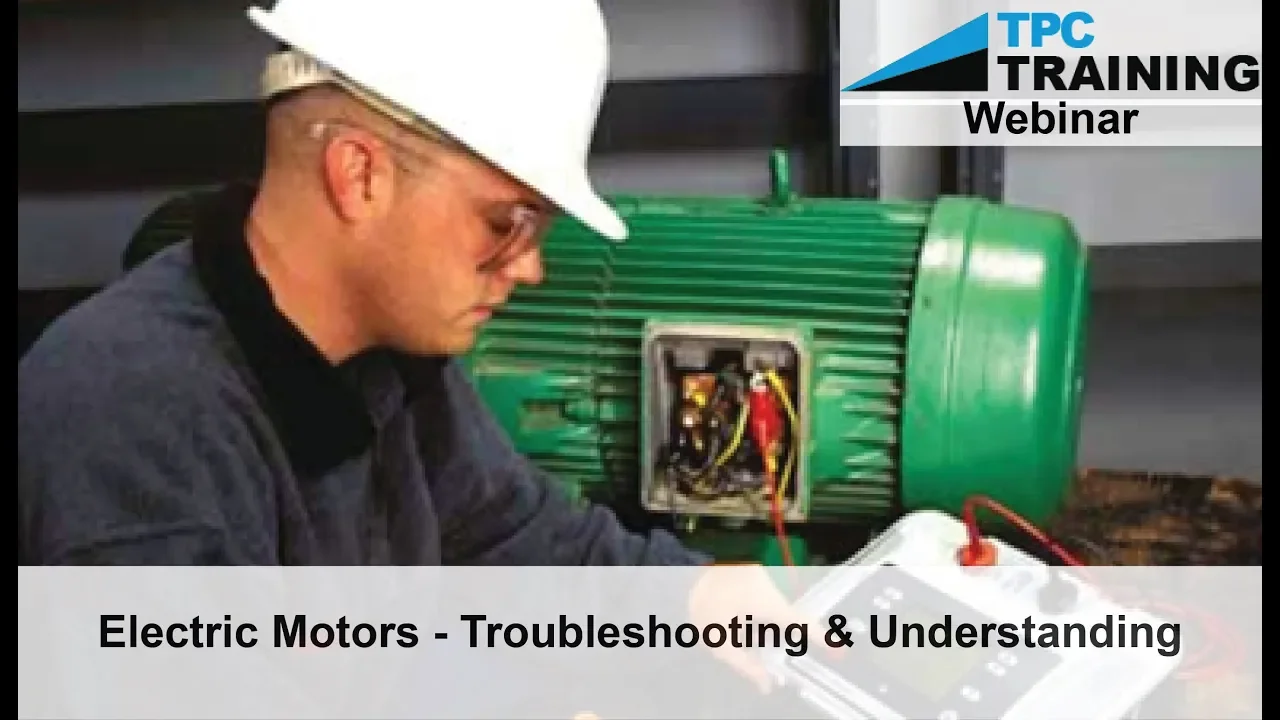
Electric Motors Troubleshooting and Maintenance Techniques (Webinar) | TPC Training
999.4K
Heat is the primary enemy of motor insulation, causing gradual deterioration. Common failure causes include overload, contaminants, phase loss, bearing failure, misalignment, and natural aging. Preventive maintenance extends motor life: keep motors clean, lubricate bearings per manufacturer specs, monitor alignment, and perform regular inspections. Thermal imaging detects overheating before damage occurs. Semi-annual or annual megohmmeter testing predicts insulation failure.
Click to watch →
Upgrades
Motor Test
Solution
Design
Testing
Upgrades
0:00- 1
Incorporating viewer feedback for RC boat enhancement.
- 2
Focusing on propeller size and motor placement.
The Continued Relevance and Advantages of Brushed Motors in Specific RC Applications
While brushless motors are often framed as the ultimate upgrade due to their superior speed, efficiency, and longevity, brushed motors remain highly relevant and are often superior for specific RC disciplines. In rock crawling and trail driving, brushed motors deliver unmatched ultra-low-speed control and smoother start-up torque without the 'cogging' or stuttering common in budget-friendly sensorless brushless systems. Furthermore, brushed setups are significantly cheaper, simpler to wire, and easier to waterproof. For beginners, budget-conscious hobbyists, and specialized crawlers, brushed motors offer practical and performance advantages that high-cost brushless systems cannot easily replicate.
Basic principles of electromagnetism, including how electric currents generate magnetic fields to produce mechanical motion.
Fundamental electrical concepts such as voltage, direct current (DC), resistance, and power (Watts).
An introductory understanding of basic DC motor components, specifically the roles of a stator, rotor, and electrical contacts.
A general familiarity with RC (Radio Control) power systems, including the basic relationship between the battery, speed controller, and motor.
In-depth functionality of Electronic Speed Controllers (ESCs), comparing brushed ESCs to complex three-phase brushless ESCs (sensored vs. sensorless).
Understanding motor specifications such as KV ratings, turn counts, torque curves, and how to select the right motor for specific RC applications.
Advanced power management, including the relationship between LiPo battery C-ratings, voltage, and motor current draw.
Thermal management, gear ratio optimization, and preventative maintenance techniques to maximize motor longevity and efficiency.
3.3M views170.6Klikes0:46@makermandanOriginal Release: 2023-09-03
I am upgrading my RC boat using your comments your most common suggestions were to use bigger propellers and to put the motor underwater normally placing a DC motor underwater is a bad idea as you can see in this experiment it stops spinning after a few seconds if we take it apart we can see why this motor has exposed brushes that conduct electricity and water causes them to short circuit but I'm using a brushless motor so there's nothing to Short Circuit it can run underwater forever I think this design will be a lot more efficient than the previous one and I also made three different propellers because you guys said that a bigger propeller will make the boat faster when it stops raining or test the boat in the water so stay tuned
Up Next

86:36
Build an Underwater ROV at Home: A DIY Guide
@SmithsonianSMS
49.7K views•2020-07-29

12:54
Triumph of Orthodoxy Icon: Byzantine Art & History Explained
@BenCallan
2.1K views•2024-08-06

9:49
FastAPI vs Flask vs Django: Choosing the Right Python Web Framework
@TechWithTim
302.5K views•2024-05-26

1:42
Game of Thrones Opening Credits: A Cinematic Analysis
@gameofthrones
46.3M views•2011-04-18
Related Study Plans & Knowledge Roadmaps
Structured learning paths in General & Interdisciplinary Studies
general-studies
Elevator Engineering: History, Physics & Cities
01From Hoists to Safety Brakes: The Dawn of Vertical Lift
02Hydraulic vs. Traction: The Engineering Physics of Elevators
03Modern Speed, Safety, and Algorithms
+ 2 more learning modules
12h5 modules
Explore Roadmap
general-studies
Rubber: Material Science, History & Geopolitics
01Origins of Natural Rubber & Mesoamerican History
02The Chemistry of Natural Rubber & Vulcanization
03The Geopolitics of the Rubber Boom & Colonization
+ 2 more learning modules
12h5 modules
Explore Roadmap
general-studies
Containerization: Evolution, Logistics & Trade
01Ancient Trade & Bulk Cargo: Amphorae to Barrels
02The Industrial Revolution & Cardboard Packaging
03The Containerization Revolution: Malcom McLean
+ 2 more learning modules
12h5 modules
Explore Roadmap
general-studies
Textile Tech: Evolution, Labor & Global Impact
01Pre-Industrial Textiles: Handloom & Cottage Industry
02Mechanization: The Spinning Jenny to the Power Loom
03The Factory System & Global Labor Transformation
+ 2 more learning modules
10h5 modules
Explore Roadmap