








![[TRL Cal: 1-1] Cal Kit setup & Calibration procedure (TRL校正の手順)](https://i.ytimg.com/vi/6Hn4pZ-soUU/maxresdefault.jpg)


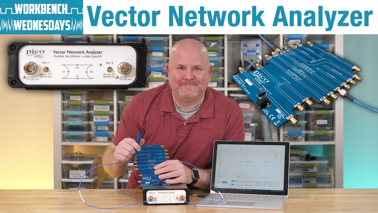







Vector Network Analyzers (VNA) require calibration for three primary reasons: correcting circuit imperfections in the instrument itself, compensating for attenuation in cables and connections, and accounting for phase delays in cables when making impedance measurements. Calibration is necessary when the reference plane changes (such as adding connector savers or cables), when measuring devices far from the VNA requiring long cables, or when using Smith charts for impedance measurements where phase delays can cause significant errors. The calibration process involves presenting known reference standards (short, open, and load) to establish a baseline correction for the measurement system.
Master VNA Calibration: When, Why, and How | RF Measurement Guide
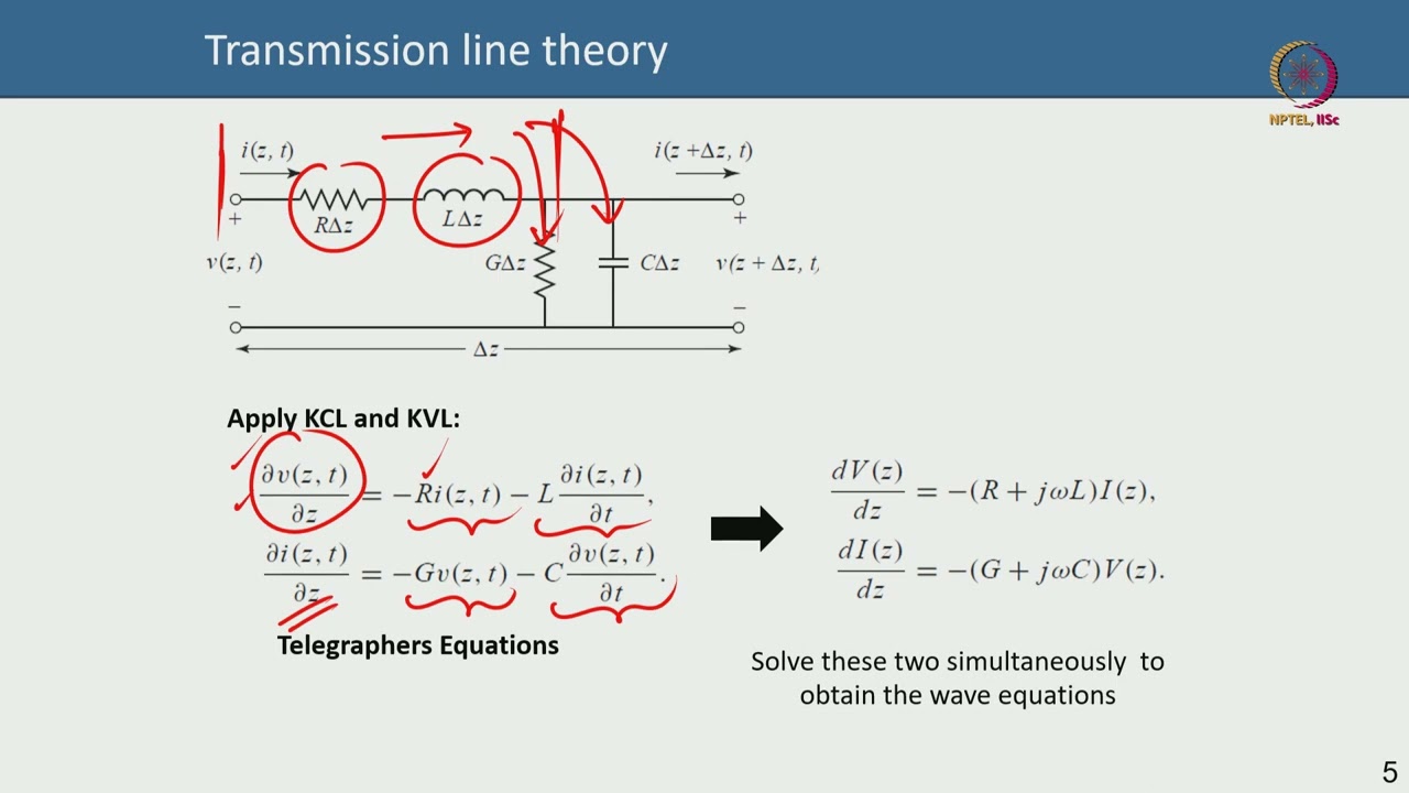
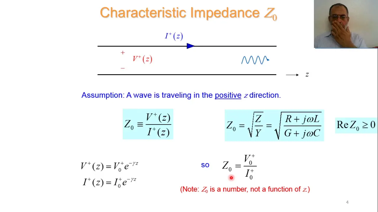
Added:Fundamental concepts of RF (Radio Frequency) and microwave transmission lines, including characteristic impedance and wave propagation.
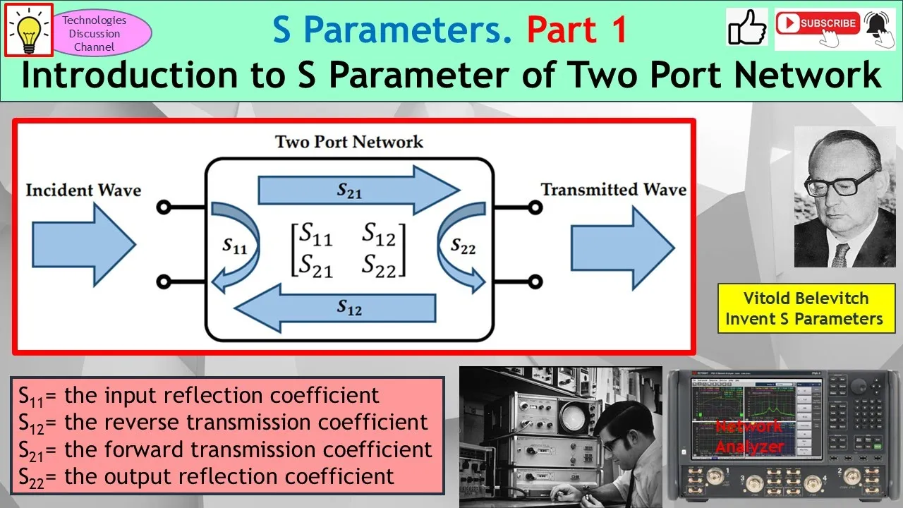
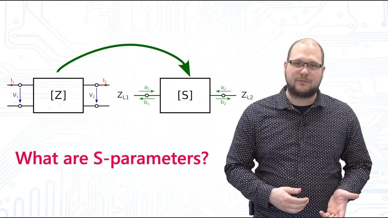
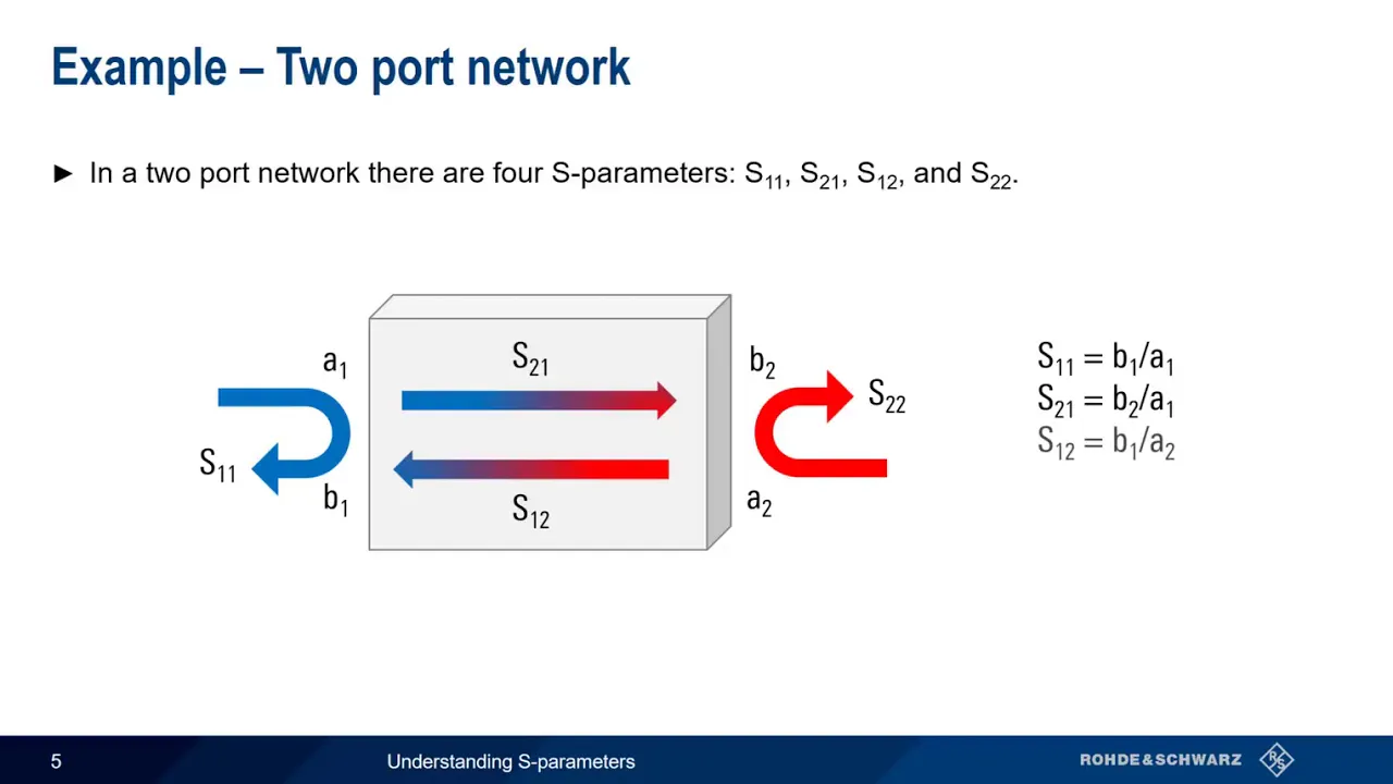
Basic understanding of Scattering Parameters (S-parameters), specifically what S11 (input reflection coefficient) and S21 (forward transmission coefficient) represent.
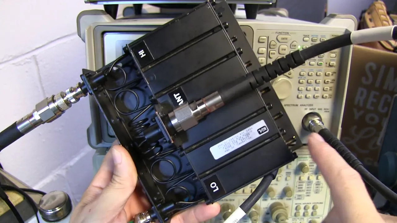
The core operational difference between a Vector Network Analyzer (VNA) and a Spectrum Analyzer.
An awareness of measurement error sources in high-frequency setups, including systematic, random, and drift errors.
Advanced calibration methodologies such as TRL (Thru-Reflect-Line) and electronic calibration (ECal) modules.
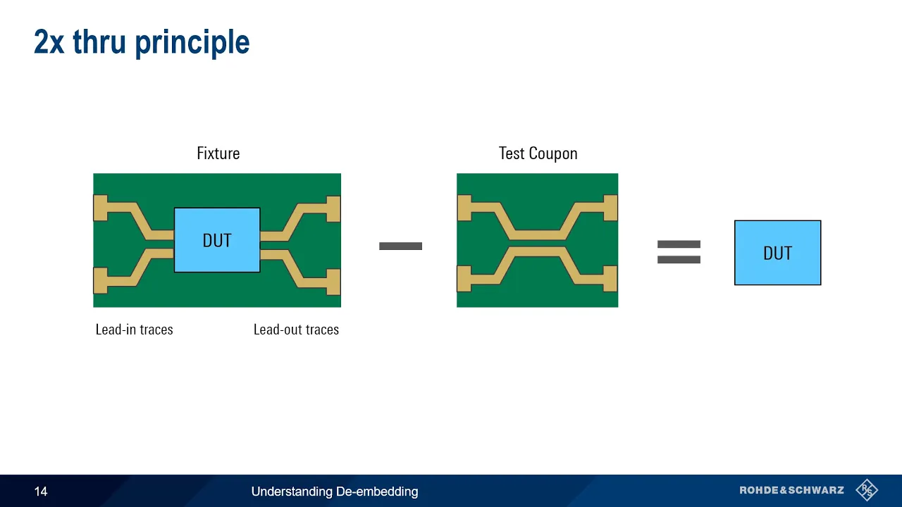
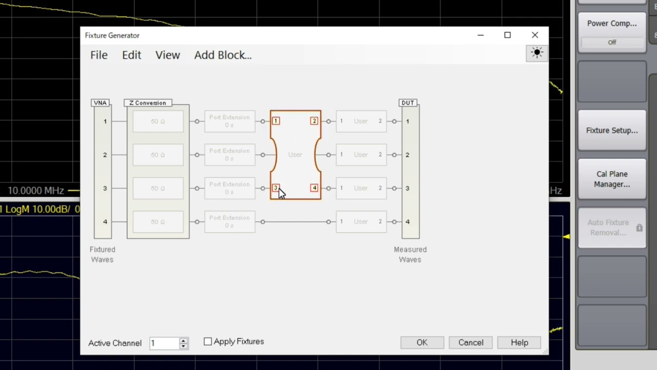
De-embedding and port extension techniques to mathematically remove the effects of test fixtures and cables from your measurements.
Practical RF circuit design and impedance matching on a Smith Chart using real-world VNA measurement data.
Characterization of active RF devices, such as measuring amplifier gain, output power, and non-linear distortion.
27.6K views590likes25:54Original Release: 2020-11-15
in this video we're going to talk about how to calibrate a vector network analyzer we'll be using this nano vna for the demos but in general this material applies to any vector network analyzer or any vna when you purchase a nano vna you usually get some accessories i got this load or 50 ohm termination a short and a little open that just doesn't do anything because quite frankly that's a pretty decent open at these frequencies they also typically give you a couple of short cables for doing s21 cal or for connecting to the things you're going to measure and a couple of adapters female female sma and male male sma whether or not you'll need the short open and load depends on what you're going to do my nano vna came calibrated and so in general i don't really need these however i did install some connector savers on here so that over time i won't strip the threads and that changed the length from the port 1 out to here from where it was and that required a recal so when do we need to worry about calibrating the vna well there's basically three reasons to calibrate first one is to correct for circuit imperfections in the instrument itself i said it came calibrated for this nano vna and that's true and so most of that was already fixed as long as i didn't mess it up now if i mess it up if i change something and save it then i may write over that calibration that came with the instrument and i might need to recalibrate a second reason is to correct for attenuation in cables and connections used in the measurement so for example here is a 5 meter cable this 5 meter cable at the higher frequency end of the range has enough loss that we need to correct for the attenuation maybe several db and last but not least especially when we're using smith charts for measuring impedance we need to correct for phase delays in cables whatever interconnection we have between the instrument and the device under test we need to correct for phase delays so let's take a look at each one of these starting with correcting for circuit imperfections that's most easily demonstrated by going to the cal menu from the top level menu i hit cal and it says correction it's highlighted i'm just going to hit it to turn it off and now you can see what happened at the low frequencies we have a couple of db drop from the 0 dbs 1 1 which was the calibrated line there at higher frequencies we have even more drop s21 should be very low down here because port 1 is not connected to port 2 but it actually jumps up and that's due to limited isolation inside the instrument from port 1 to port 2.
and that can be corrected for to a certain extent if you have the right test setup to demonstrate when you might need to do cal for number two to correct for attenuations and cables and connections used in the measurement i have this set up with port one connected to port two using the cable i used during the calibration and we have a nice blue line here at 0 db across frequency from 50 kilohertz out to 1 gigahertz correction i've turned back on but suppose the device we want to measure is not such that we can put it right at the vna maybe we need some long cable links to go to it this is a two meter cable this is another two meter cable over here and what i've done is connect them together with the mail to mail sma that came with the vector network analyzer now the s21 line is no longer flat out through one gigahertz in fact out here at 910 megahertz it's showing a loss of about three decibels and so if i calibrate again using these two cables in place then i can get rid of that loss that's part of the cables and not part of whatever i'm trying to measure and the third basic reason to calibrate a vna has to do with when you're making impedance measurements as we'll see we get phase delays along the coax cables and we need to calibrate those out if we're going to be able to read the impedance properly on a smith chart so to illustrate this i'm going to go to the trace menu and make sure i'm pointing to trace 1 so i tap it twice it's highlighted over here now i'll hit back and then go to format and change it to a smith chart so as it should be for an open circuited port 1 the readout is over here on the right hand side of the smith chart which we know from a previous video or you may have known it already that this is an open circuit but let's watch what happens when we attach a cable onto here that was not present when we did the original calibration for this i'm just going to use one of the original 20 centimeter cables that comes with the vna and i'm going to attach it to port 1.
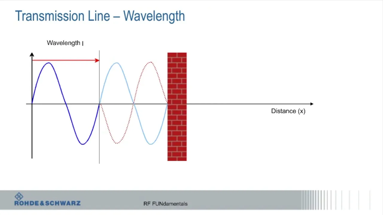
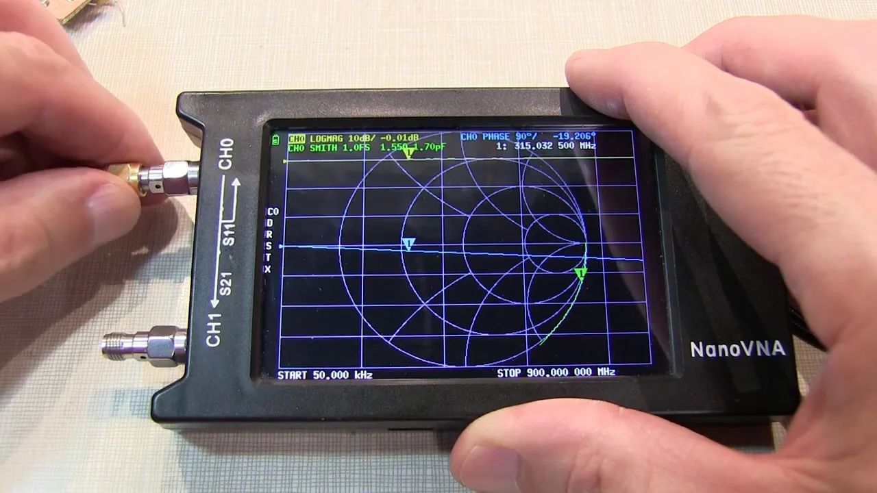
the cable is still an open circuit but now the point is not over at the right hand side at least not at all frequencies it's instead anywhere on the chart it's wrapped around the chart several times in fact i move the marker to 250 megahertz and the marker is now over here on the left hand side which we know is a short circuit so an open circuit has now become a short circuit at 250 megahertz but if we're going to connect this cable up to an antenna for example we want to know the impedance at this location we know right now that that's an open circuit but it's not reading out as an open circuit and so what we need is a calibration to what's called this reference plane having this cable in here and calibrating to an open which is physically located at this distance from port 1 on the analyzer now an important point that's true for this particular setup at 250 megahertz but if i move the marker down to a lower frequency in fact down to 50 kilohertz it's over here and it's a nice open circuit readout as it should be and at any reasonably low frequency maybe up to a megahertz or something like that we're okay but at higher frequencies we are decidedly not okay and we need a calibration now why does this happen when we just put a short length of cable onto the nano vna well the answer has to do with how short is short and the answer to that is it depends on the wavelength which depends on the frequency of the signal and that's what we're going to walk through here and try to explain in a previous video titled nano vna demonstrations coax line reflections and smith charts we went over essentially how the vna works i would encourage you to look at that video especially if you're not that familiar with smith charts but what we're going to do here is summarize that and use it to explain what was going on when we attach that short length of coax line it all starts when the nanovna launches a signal onto the line here we've represented the nano vna as a voltage source in series with a 50 ohm source resistance that's pretty decent circuit model for the vna our vna the nanovna puts out yeah a little over one milliwatt as we've seen in a previous video as well and i just represented that as a two volt source signal over here now what we've seen before in those other videos is that when you look into a coax line if the coax line is sufficiently long the signal has no idea initially what's at the other end of the line down here what it sees instead is capacitances and inductances that are formed by the line itself and through magic not really magic but through math that resolves to it looks like a 50 ohm resistance coming into the line then that signal which is composed of a voltage but also a current which is one volt divided by 50 ohms flows down the line from left to right and it takes some time because there's a velocity of propagation which is not infinite it's the speed of light or actually in coax about maybe 66 percent it depends on the type of coax and that signal is going to get reflected because it cannot go into the open circuit there's current coming out here but has nowhere to go and so the only thing that can happen is a new current gets generated which comes back in the other direction that's what a full mathematical analysis will show us but physically that's what's going on in the example we've been looking at our coax which is 20 centimeters long is about one quarter of a wavelength so we would expect that the delay would be on the order of one quarter of a cycle and that's what we're representing here in the diagrams on the left hand side is the signal that was launched onto the coax it's a sine wave this is a time axis is a voltage axis and it's a sine wave at whatever frequency we're dealing with that generates the forward traveling voltage wave and an associated current wave and the voltage and current which carries power with it gets to this other end a quarter of a cycle later but notice that the voltage here is shifted to the right in time or delayed in time by one quarter of a period what happens when it reaches the end of the coax in our particular example we have an open circuited coax so the signal is going to get reflected that power cannot go anywhere so it's going to be forced to get reflected back in a detailed mathematical analysis what we would find is there's a current trying to come out here it cannot go out there because there's nowhere to go in an open circuit so an equal and opposite direction current gets created at the open circuited end comes back into the coax sees 50 ohms and generates a voltage which is basically the same as the voltage that was coming this way but those two voltages add so what we have is this picture the signal that came from the generator looks like this the signal that now is generated at this end and flowing back toward the generator looks like this and it's identical what that means is at this end of the line s11 the reflection coefficient has a size of one and has a phase relationship these two waveforms are in the same phase phase relationship of zero degrees so s11 is one at an angle of zero degrees and that's what it should be for an open circuit however that signal is now coming back to the left and it has a propagation delay coming back and so it arrives later and looks like this so compared to the outbound wave that it's now got an opposite phase or 180 degree phase so what does the network analyzer see instead of s11 equals one at an angle of zero degrees it doesn't see what's going on at this end it only sees what's going on at this end and now it's got the magnitudes are the same but the phase relationship is 180 degrees so instead of one at an angle of zero degrees that it should report for an open circuit it's telling us it's one at an angle of 180 degrees and that's what you would have if you were measuring a short circuit so it displays it as a short circuit but it only looks like a short circuit at one frequency in our example 250 megahertz with our 20 centimeter line now if you've got a nano vna or any other vna yourself and a short piece of coax like this 20 centimeter line i would encourage you to hook it up and try this all right let's talk about how to calibrate the vector network analyzer or in our case the nano vna in this video we're just going to talk about an one port calibration in particular right now an s11 cal then we'll briefly go over s21 cal as well so here's a basic one port s11 calibration procedure broken down into eight steps step one decide if you actually need to recalibrate or calibrate the vna so i want to do this particular calibration up through 500 megahertz instead of the default one gigahertz that it's set on now so i'm going to bring up the menu again i'll select stimulus and stop frequency i'm going to change that to 500 megahertz in the case of the vna i got it came calibrated to the connector at port one but when i added these connector savers i decided to recalibrate because it threw off the calibration at high frequencies a little bit now as we've shown in this video when i added this short cable here that threw off the calibration quite a bit for the case of smith chart measurements when i actually want to measure the impedance value however if i was just going to look at s11 log magnitude the losses on this cable are probably not sufficient enough to matter so i probably would not recalibrate because on the log magnitude scale here i get a nice flat 0 db line almost perfectly across frequency even out at the high frequencies the cable loss is not very much because it's only 20 centimeters long however let's say i was trying to measure something at the end of this 5 meter coaxial cable that's open circuited at the end and should have a reflection coefficient of 1 which in db is 0 db this line should be as we saw a minute ago flat at 0 db but instead it's decaying that's because i've got losses along the line and out here i've got probably about 6 db of loss out here at this higher frequency so steps 1 and 2 are somewhat the same depending on the cable length that is where the reference plane is relative to the nano vna port 1 i may or may not want to recalibrate i need to decide on that reference plane and that consists of the configuration of cables and connectors between the vna and the device being measured the next thing you'll want to do before you start the calibration is to make sure you have some good references usually termed shorts opens and loads one of each and the rest of the steps in the calibration are four through eight all right let's get started so i'm going to do step four set the measurement channel to s11 bring up the menu go to display channel and i have s11 here that's what it was already on the s11 was highlighted and so i didn't have to do that but you want to make sure that you're calibrating with the correct channel i'm currently in log magnitude display so again i'm going to go to the menu and i will select format and smith chart the next step is to turn off the existing calibration so i will hit back from the menu i was in hit cal and i hit correction to un-highlight it notice when i did that that the s11 plot is now vastly different this is due to the inaccuracies in the circuitry of the device itself remember when we talked about why you want to calibrate one of the main things was the calibration fixes inaccuracies in the instrument itself when i turn off the correction those become blatantly obvious step 6 is to start the calibration and present the short open and load references so i go to cal correction is off i'm going to hit calibrate and this is an open or i could put this little open cap on the end of it at these frequencies it doesn't matter at higher frequencies it does i'm just going to leave it off and hit open all right the next thing is it's telling me it wants me to present a short so i will put that on now once it's all settled down i hit short now it says put the load on so this is my 50 ohm termination load that i put on it should go somewhere toward the center and it does and i hit load and at this point since i'm only doing an s11 cal i'm basically done we'll cover isolation and through later so i'm going to hit done and it automatically prompts me to say where do you want to put it i'm going to save it in 4 because i don't want to write over things that i like from previous cows 4 is kind of my temporary dummy place that i use when i'm experimenting the last step is a verification step and we've already got part of that the load is still on it it's at the center quite well i'm going to take the load off where should it go should go over to the right hand side and it does so that looks good and lastly let's put the short back on remember the short is the cap that has the little pin in it put that on and that looks like a good short so i think i have a decent cal here as one final check i put a 75 ohm resistor at the end here and let's see how that measures hmm okay well 75 ohms should be along the horizontal line here in the center of the smith chart instead it's up higher the reason for that is i've got the marker set at 470 megahertz and at 470 megahertz this is not actually a good 75 ohms it's actually 75 ohms in series with the inductance of the wire that is part of the resistor and so that's what we're seeing here it reads out as 77 in series with about nine nanohenries so that's not a problem with the calibration that's actually measuring the physics of what a resistor looks like when you include the lead lengths in it of course it is possible to create good 75 ohm resistances without that lead length this is the one i just measured here is a surface mount 75 ohm resistor and this is on the rf demo kit that we showed in a previous video so finally let's talk about calibrating for s21 s21 is the gain from port 1 to port 2.
and with a cable connecting the two assuming there's no loss in the cable we should have zero db if you look at the blue trace that's what we have here i've returned to my original cal that either came with a device or i wrote over it when i added my connector savers i can return to that by recalling wherever it's stored in my case it's recall 0. now for this demo i'm not interested in s11 so i'm going to turn off that trace leaving only s21 so this s21 cal looks fine it's zero db from 50 kilohertz to one gigahertz so when would i need to recalibrate for s21 here's one answer if i'm going to measure something which is far away from the network analyzer then i'll need long cables here i have a two meter cable connected to a 5 meter cable through this junction here and we can see that out at the high frequency end around 1 gigahertz looks like we have about 4 db of loss through here even at 500 megahertz in the middle we've got a couple of db of loss and that might be important for whatever measurements we're trying to make it might be important to get that back to zero so here's a quick calibration to do that let's bring up the menu again i'm on trace 1 and i've turned off trace 0.
if i was on trace 0 first thing you want to do is make sure that you select trace one before you do the cal so i'm going to leave trace zero on turn on s11 turn on trace one make sure it's highlighted it was already on but now it's highlighted then i'm going to hit the back key here back up again hit cal i think i could leave correction on but in general i like to turn it off before i do stuff so i turned it off we have even more loss now but we're going to calibrate and i'm just going to do a through cal so i'm going to hit through and then done and then i'll save that in my temp that i always use temp 4 register 4 and we notice now that we're basically 0 db from 50 kilohertz to 1 gigahertz as we wanted now i'd like to say that that's all there is to it but there is a little secret about these nano vnas they are not the same quality as a lab instrument let me show you what i mean if i disconnect the cable from port 1 then what should happen well there should be no gain from port 1 to port 2 so the blue line should move from 0 db down to the bottom of the screen let's see what happens when i disconnect it okay that is not the bottom of the screen it should be down here but it's actually let's see this is 0 db minus 10 minus 20 minus 30 minus 40 db to minus 50 db across much of the frequency range now you might argue that that might have to do with the fact that this cable is near that connector but if that were true then as i move it in and out it should go up quite a bit as i get closer if there was capacitive coupling and that's not the case the problem is that there's internal limitations in the circuitry that prevent high isolation from port 1 to port 2 inside the device and i skipped the isolation step when i did the cal you can to some extent improve your measurement capability beyond what you see here if you do the isolation step but that's kind of a long and involved discussion so i don't think we're going to do that here today so we're going to end it here these were the basic reasons to calibrate the vna and we've illustrated all of these i hope you've enjoyed it and if you have any questions leave them in the comment section below and i check periodically not real often so i apologize if i don't get back right away and as always thank you for watching
Up Next
21:35
Antenna SWR Tuning with a NanoVNA: A Practical Guide
@ChristopherLum
26.2K views•2022-04-25

12:54
Triumph of Orthodoxy Icon: Byzantine Art & History Explained
@BenCallan
2.1K views•2024-08-06

9:49
FastAPI vs Flask vs Django: Choosing the Right Python Web Framework
@TechWithTim
302.5K views•2024-05-26

1:42
Game of Thrones Opening Credits: A Cinematic Analysis
@gameofthrones
46.3M views•2011-04-18
Related Study Plans & Knowledge Roadmaps
Structured learning paths in General & Interdisciplinary Studies
general-studies
Elevator Engineering: History, Physics & Cities
01From Hoists to Safety Brakes: The Dawn of Vertical Lift
02Hydraulic vs. Traction: The Engineering Physics of Elevators
03Modern Speed, Safety, and Algorithms
+ 2 more learning modules
12h5 modules
Explore Roadmap
general-studies
Rubber: Material Science, History & Geopolitics
01Origins of Natural Rubber & Mesoamerican History
02The Chemistry of Natural Rubber & Vulcanization
03The Geopolitics of the Rubber Boom & Colonization
+ 2 more learning modules
12h5 modules
Explore Roadmap
general-studies
Containerization: Evolution, Logistics & Trade
01Ancient Trade & Bulk Cargo: Amphorae to Barrels
02The Industrial Revolution & Cardboard Packaging
03The Containerization Revolution: Malcom McLean
+ 2 more learning modules
12h5 modules
Explore Roadmap
general-studies
Textile Tech: Evolution, Labor & Global Impact
01Pre-Industrial Textiles: Handloom & Cottage Industry
02Mechanization: The Spinning Jenny to the Power Loom
03The Factory System & Global Labor Transformation
+ 2 more learning modules
10h5 modules
Explore Roadmap