








![[33] Serway Physics CH14 유체 동역학, 베르누이 방정식(원리), 점성 유체의 흐름, 유체 동역학의 다른 응용들](https://i.ytimg.com/vi/-fllPZhKZ7U/maxresdefault.jpg)







![How To Do Smoke Flow Visualization Well [Flow Viz #2]](https://i.ytimg.com/vi/CLD_roaYM8w/maxresdefault.jpg)




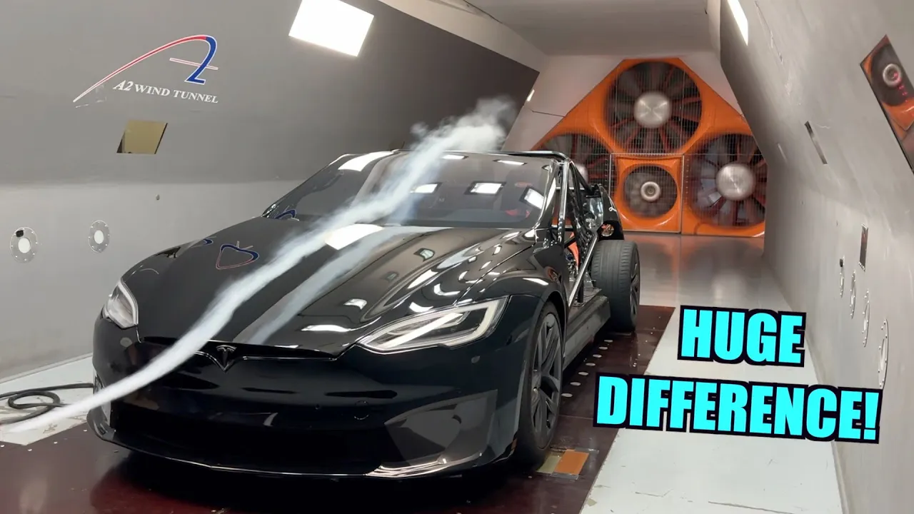
A wind tunnel creates controlled laminar airflow for aerodynamic testing by using a settling chamber to gather large volumes of air at low speed, a contraction cone to accelerate the airflow (typically with a 6:1 ratio and 12-degree angle), flow straighteners (honeycomb mesh and screens) to eliminate turbulence, a test section for placing models, and a diffuser to recover static pressure and buffer against fan pressure pulses; this systematic approach allows designers to visualize and analyze complex airflow patterns over aircraft components like wings, winglets, and control surfaces during the design process.
DIY Wind Tunnel Build Part 1: Design and Aerodynamics
Added:Basic fluid mechanics principles, specifically Bernoulli's Principle and the Continuity Equation.
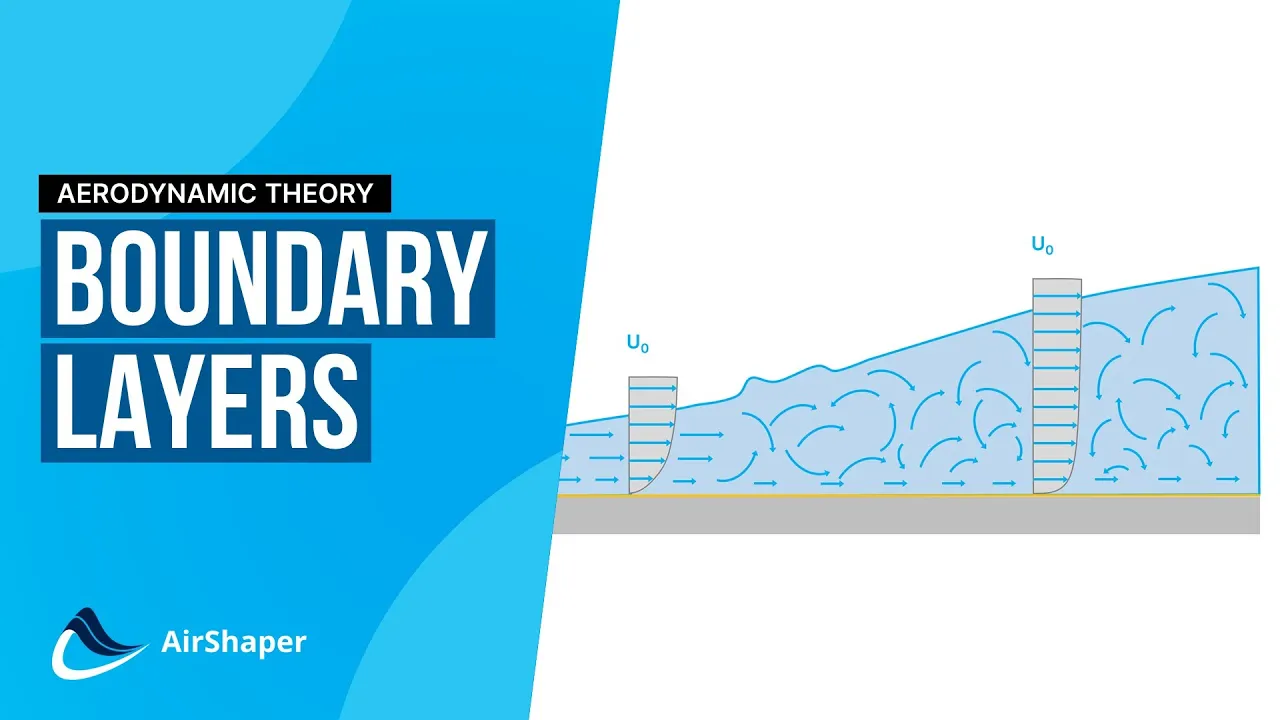
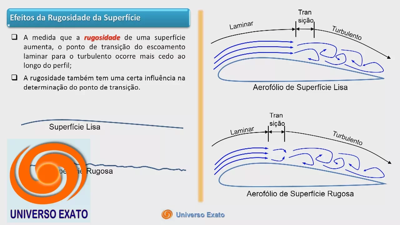
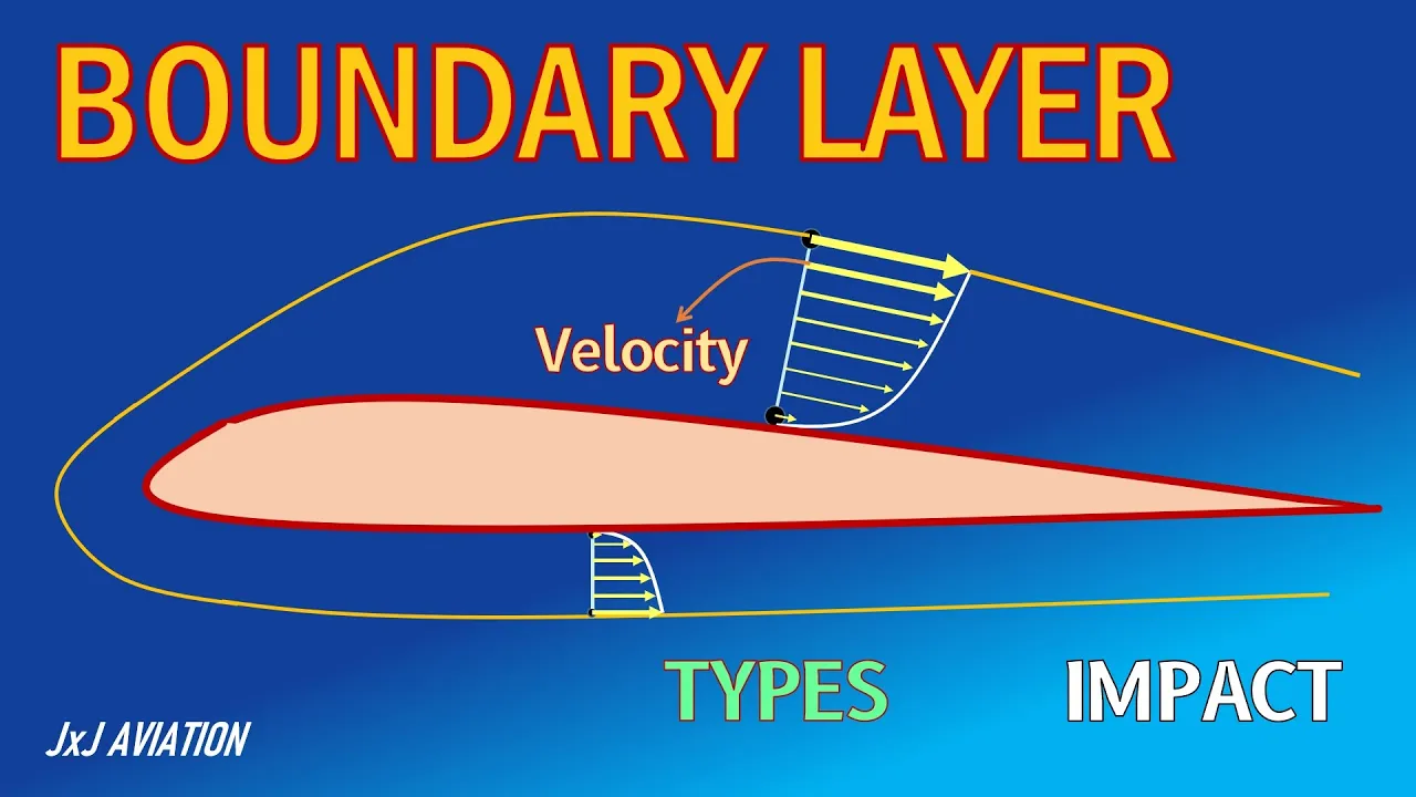
The distinction between laminar and turbulent fluid flows, and how boundary layers form.
Fundamental aerodynamic forces including lift, drag, and the concept of aerodynamic drag coefficients.
An understanding of fluid properties such as viscosity, air density, and the significance of the Reynolds Number.
Methods for calibrating wind tunnel velocity and pressure using instruments like Pitot-static tubes and manometers.
Design and integration of data acquisition systems, such as load cells and multi-axis force balances, to measure lift and drag.
Flow visualization techniques, including smoke generation, tuft testing, and schlieren photography.
Application of wind tunnel testing to optimize real-world geometries, such as airfoils, automotive bodies, or sports equipment.
77.5K views1.6Klikes17:07Original Release: 2019-04-06
hey guys what's up most of you know that I design and manufacture flying wings and those of you who didn't know now you do I've been doing this for about a year little over a year now and it's been a lot of fun I've really enjoyed it that's not to say though that it hasn't come with its own set of challenges Manufacturing aside even the design and the testing can be a very long and slow and iterative process mainly because it's difficult to understand what the airflow is doing on a wing when it's up in the air away from you I've had some pretty good luck doing some stall testing with Telltale's and some onboard video and this is this has been it's been helpful but again it's it can be slow and tedious and it really requires that we've got a a wing that's completed and in the air I'd really like to get a better understanding of the complexities of the airflow over the airfoil and around the winglets and over the control surfaces around antennas camera mounts how it flows around the motor mounts and to the prop all of that I'd love to understand that better during the design process early on and to that end I've decided that I'm going to build a wind tunnel yep I'm building a wind tunnel really like the way that sounds [Applause] [Music] [Applause] [Applause] okay so whenever I start a project like this I like to take time and do as much research as I can and this project is certainly no exception so my first stop was hitting YouTube and seeing quickly what others had done and what's available and what I found on YouTube is that there's a pretty wide gap in the content at one end we have these large multi-million dollar testing facilities for Boeing and NASA and and some of the Formula One teams which which are great but clearly way outside my budget and then there's not much in the middle and then we get down to the smaller stuff there's a bunch of DIY projects and classroom projects and things like that which I think are much too small scale for the type of project that I want to do so it was pretty clear I was going to need to do quite a bit deeper research and what I came across was some commercial white papers and some academic publications that really gave me a pretty good understanding of the wind tunnel design and some of the design criteria which is what I was really looking for I'm going to design a wind tunnel to meet my needs and I really want to know what that criteria is now the most important thing we need is good clean free laminar airflow that is air flow without turbulence or vortices and this is going to be the closest representation to what the airfoil and the aircraft is going to see in free air but how do we accomplish this this is the basic shape of a wind tunnel and contrary to popular belief the fan is actually on the outlet side the air is sucked through the tunnel instead of balloon because the blown air has a lot of turbulence the large settling chamber a contraction cone opening allow large volume of air to enter the structure at low speed the relationship of flow rate to cross sectional area and velocity look like this for a given flow rate an increase in area will yield a decrease in velocity this is great because it means we can gather a large volume of air at a low velocity which decreases the turbulence in the flow we can still get vortices and turbulence in the inlet air so we need to use a flow straightener to cut these vortices and give us a slow a smooth laminar flow this is done by using a large honeycomb mesh and some screens now that we have laminar flow we need to speed it up to our test velocity but still keep it laminar this is done by the contraction cone arguably the most important part of the wind tunnel the contraction ratio can vary depending on the design goal but a six to one ratio is probably going to be enough for the design I'm working with also we want to try to keep our contraction angle around 12 degrees the flow now moves through the Test section and around our test structure then the flow moves into the diffuser the diffuser is important because it lets us recover the static pressure a little bit to improve efficiency and it acts as a buffer to the pressure pulses from the fan blade these pulses can travel back up through the tunnel and affect the flow in the test chamber the angle of the structure should be around 3 degrees to keep the air from separating from the walls ok now that we know how this is supposed to work let's take a look at the parts I'll be building we start with the Test section this will be a 12-inch square section 24 inches long it'll have a plexiglass window on the side and later I ended up adding one to the top as well I'm using a 16 inch 12 volt fan that's capable of about 2,000 CFM the diffuser will go between the fan and the Test section and will be about 38 inches long next the contraction cone the curve shape will be made out of eighth inch masonite board and will be housed inside the plywood frame this also houses the settling chamber and the honeycomb mesh the opening here will be 30 inches square and it will be about 42 inches long of course I will need some sort of stand to support the whole structure I intended to pretty much film everything but my GoPro died early on and it took me a couple days to get it fixed I ended up choosing half inch paint grade plywood for the structure because I thought it was light enough I looked at some cheaper products like MDF and was afraid that that would just be too heavy to manipulate move around these large pieces because I had a full set of measure drawings I went ahead and just cut everything at once now I figured that the contractual cone shape was going to be the toughest part to build and I'm using here at 8 Finch masonite board and I have a block of wood under the third point of the cone and I'm just bending this over to give me that reverse curve shape that I'm looking for now mathematically it's not perfect but it's a lot better than just having the cone itself give me a pretty good shape but there's pretty close to whatever now the hardest part actually basically two of these pieces had to have the outside it took a while and doing it myself difficult here's the completed contraction column you can see the reverse curve shape inside and really just all held together so look from the outlet side don't mind the shop it's a mess this project really was a disaster for the shop so I moved on next to the test chamber and I wanted the plexiglass to sit flush with the inside so I just built it in it's the same thickness as the masonite so I get a nice flush appearance on the inside here I'm just screwing the test chamber together don't pay any attention to the wobbly workbench it was driving me crazy and here's a look inside the test chamber and you can see that Plexiglas is flush against the masonite which will really reduce turbulence inside now the next part was putting together the settling chamber the settling chamber was approximately six inches thick by the 30 inch square and this chamber would be mounted at the beginning of the contraction cone and will house the honeycomb mesh and the screens to remove the vortices from the airflow and promote the laminar airflow and this is pretty much just glued and screwed together as his most of the structure a lot of pieces are actually just screwed together because I wanted the ability to take panels off if I needed to to make adjustments now that the contraction cone is done and the settling chamber it was on to creating that honeycomb mesh and I really couldn't find anything that would work well I wanted something about two inches thick and with a quarter inch holes so what I ended up doing was buying a bunch of boxes of quarter-inch soda straws now these are ten and a half inch straws in the box so what I ended up doing was just marking two inch segments on the box and cutting them in bulk on my bandsaw this was a pretty slow process but once I figured out the tricks to cutting the ends and putting pieces over the ends to keep all the little bits from falling out it started to move along pretty well and after five boxes I actually got the hang of it once they were cut it was just a matter of stacking them inside the settling chamber and stacking and stacking I'm using a piece of screen on the front to hold them in and then as I moved up I stapled another piece of screen on the back to hold all the straws in place because I really didn't want any of them falling out I calculated that I needed about 8,000 pieces to fill this and when I finished all five boxes I found that I was about 1500 straws short so had to call Amazon and place an order for another box here where's the construction of the support structure basically it's just a two-by-four frame that's screwed together and then I screwed the test chamber directly to it now the test chamber is the only piece that's actually screwed to the support structure everything else is supported without screws so it can be removed once this piece was on I can go ahead and put my contraction cone on and here I'm fitting the settling chamber over the front of the contraction column now I'm putting together diffuser and the diffuser fits between the test chamber and the fan and acts as a buffer to buffer against the pressure pulses from the fan and to recover a little bit of static pressure tolerances were a little tight and had a little bit of trouble but eventually I managed and you can see I'm holding these pieces together with hinges they hold very tight especially on these odd angles and they still make this removable by pushing the pins out this is the access panel on the back and eventually I will build in the airfoil support structure through this door now comes fitting the fan and this is a 12 volt 120 watt fan for a radiator and it's just going to go directly onto this back plate once I get the hole cut out you can see I've got a 12 volt power supply and eventually I picked up a variable speed controller for it once the fan is screwed on it's just a matter of screwing the back plate right on to the end of the diffuser once this is on I just perform a quick test to make sure everything works at this point I think I'm going to stop this video and we will pick up in version 2 because from here on out pretty much everything is getting the smoke system working and the lighting and there we have a successful fan test okay so I hope you guys liked the video or at least found it somewhat interesting in part two we're going to take a look at the design and redesign and subsequent redesign of the smoke system and some of the complexities and issues I ran into with that we'll take a look at the lighting for getting some video and images and we'll do some initial testing and see how it all came together until then I will catch you guys on the next one [Music]
Up Next

9:33
Building a Homemade Subsonic Wind Tunnel: High School Aerodynamics Project
@jameswadhwani7023
40.5K views•2021-07-03

30:32
Ultrasonic Transducers: Resonant Frequency Measurement and Horn Design
@imajeenyus42
229.9K views•2017-02-22
20:08
Wind Tunnel Build Part 2: Airfoil Support, Smoke & Lighting Systems
@DefiantWings
50.2K views•2020-03-20

33:39
How a Student's Question Saved a NYC Skyscraper from Collapse
@veritasium
22.8M views•2025-04-26
Related Study Plans & Knowledge Roadmaps
Structured learning paths in Engineering
engineering
Building Acoustic Levitators: Physics & Arduino
01The Physics of Sound and Standing Waves
02Piezoelectric Transducers and H-Bridge Drivers
03Arduino Programming: Generating 40 kHz Signals
+ 2 more learning modules
14h5 modules
Explore Roadmap
engineering
Building Peltier Cloud Chambers: Particle Tracks
01Cosmic Rays & Cloud Chamber Physics
02Thermoelectric Cooling (TEC) Fundamentals
03Custom Liquid-Cooling Loop Design
+ 2 more learning modules
18h5 modules
Explore Roadmap
engineering
Yagi-Uda Antennas: Modeling, Build & VNA Test
01Introduction to RF and Antenna Fundamentals
02Yagi-Uda Antenna Design Principles
03Antenna Modeling and Simulation in 4NEC2
+ 2 more learning modules
18h5 modules
Explore Roadmap
engineering
ECG Monitor Design: Op-Amps, Filters & Noise
01Electronics & Breadboard Basics
02Op-Amps and Instrumentation Amplifiers
03Bioelectricity and ECG Fundamentals
+ 2 more learning modules
18h5 modules
Explore Roadmap