

















![Nondimensional numbers and Similarity [Aerodynamics #4]](https://i.ytimg.com/vi_webp/29a9e_xI9Jg/maxresdefault.webp)




![[Aero Fundamentals #11] What is a Pitot Static Tube?](https://i.ytimg.com/vi/PRHbmk6rA7g/maxresdefault.jpg)



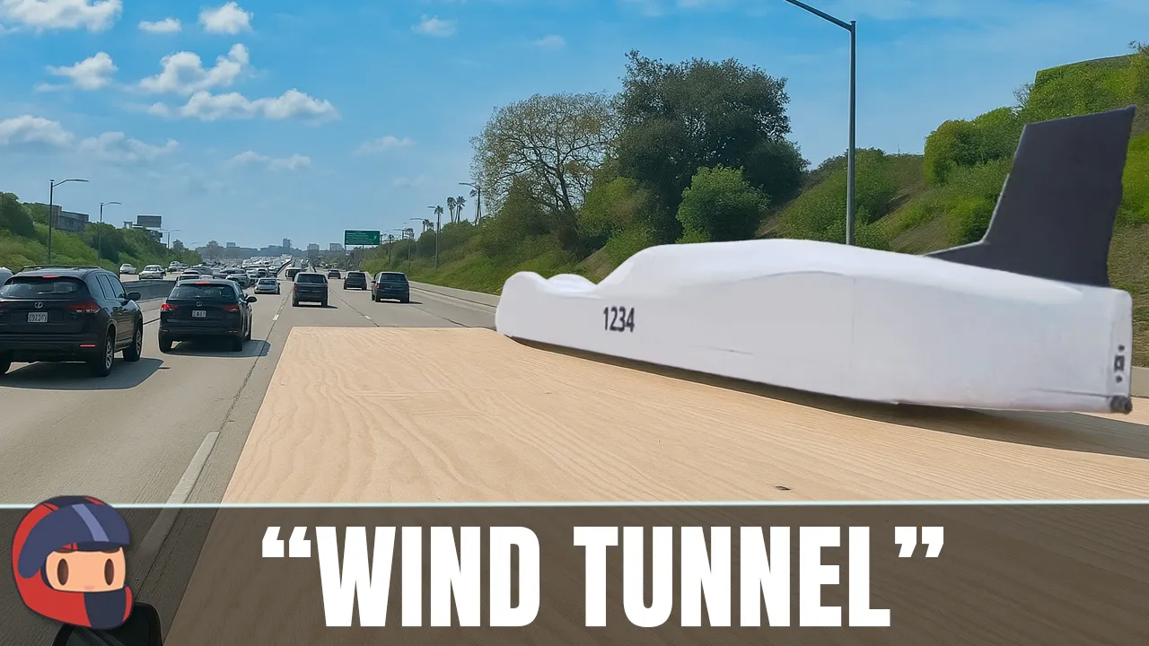
A homemade subsonic wind tunnel consists of three main sections: a contraction cone that accelerates airflow and reduces turbulence using honeycomb mesh and wire screens, a test section with load cells and Arduino for measuring lift and drag forces, and a diffuser that slows airflow and regains static pressure according to Bernoulli's principle; this setup can successfully test airfoils like flat plates and Clark Y profiles by comparing experimental results against theoretical predictions.
Building a Homemade Subsonic Wind Tunnel: High School Aerodynamics Project
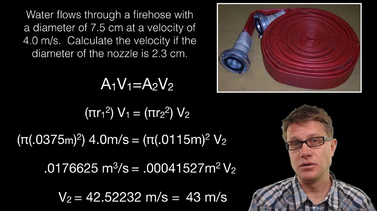
Added:The Continuity Equation and fluid conservation of mass, explaining how air velocity changes with cross-sectional area.
Bernoulli's Principle, relating fluid velocity to static and dynamic pressure changes.
The distinction between laminar and turbulent airflow patterns.
Basic aerodynamic forces (lift, drag, thrust, and weight) acting on an airfoil.
Calculating dimensionless aerodynamic coefficients, specifically the Coefficient of Lift (Cl) and Coefficient of Drag (Cd).
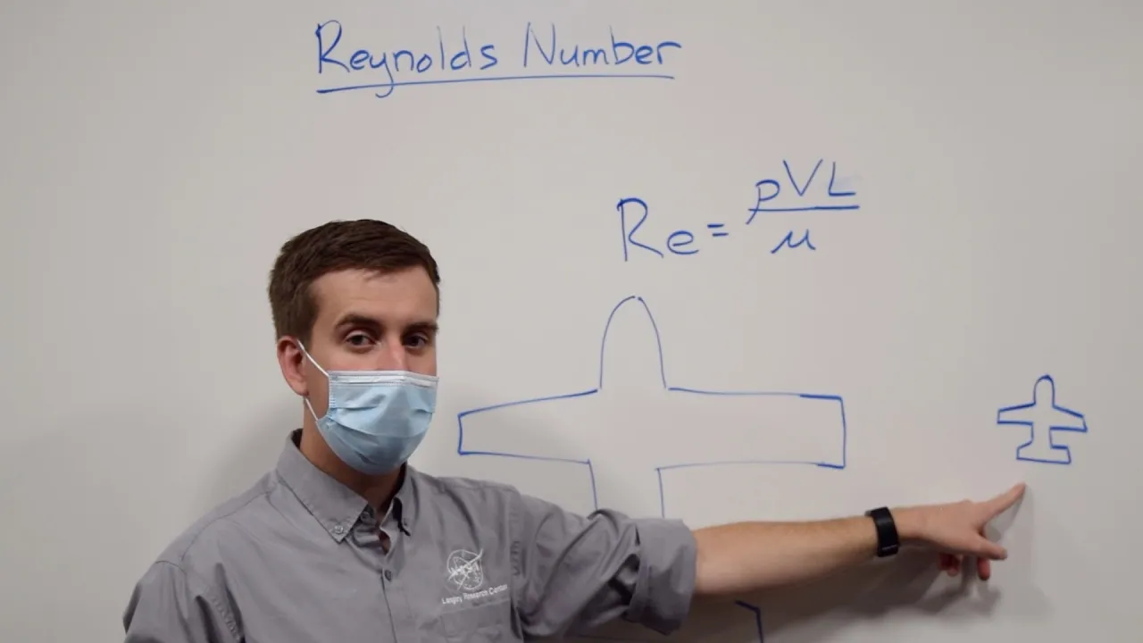
The concept of Reynolds Number and its importance in aerodynamic scaling and dynamic similarity.
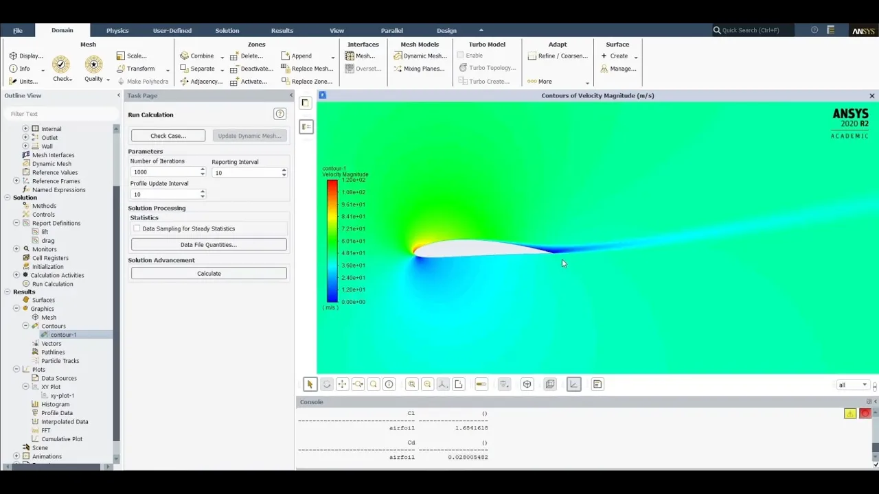
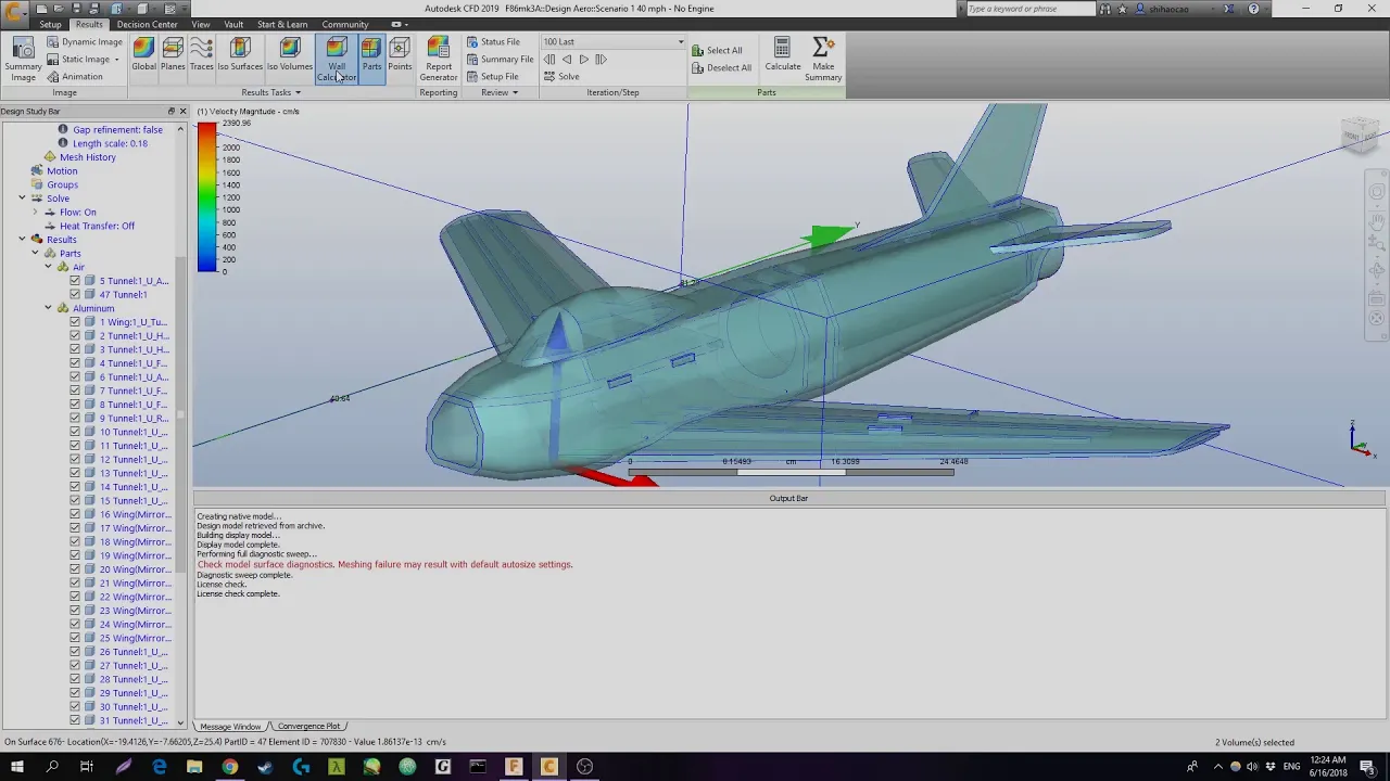
Introduction to Computational Fluid Dynamics (CFD) software to simulate and validate physical wind tunnel data.
Advanced wind tunnel instrumentation, such as Pitot-static tubes, multi-axis force balances, and laser-based flow visualization.
Supersonic and compressible flow regimes, exploring how aerodynamics change when approaching or exceeding the speed of sound.
40.5K views1Klikes9:33Original Release: 2021-07-03
well hey guys thanks for tuning in my name is James wwan I'm a recent high school graduate headed to Purdue in about a month and a half I'd like to quickly show you the homemade subsonic wind tunnel that I created as uh the final project for my high school senior year this project took roughly 100 hours or so over the course of two weeks of continuous work for um planning building and then testing and comparing my results so I'd like to quickly show you what I've done how I did it and sort of the results I was expecting and what happened along the way so stay tuned thanks so much for watching so here's the wind tunnel in all of its Glory uh I'm going to start from the front of the tunnel at What's called the contraction cone working my way through the test section and then finally to the diffuser and showing you guys what I did and sort of how I built the whole thing to start off with we have the contraction cone now the contraction cone's main purpose is to pull in a large volume of air as you can see it's pretty dang big compared to the rest of the tunnel and then constrict that air down to get a higher velocity as it gets through the test session it also serves to reduce a large amount of turbulence as it goes through so at the front here we have this very hard to see honeycom mesh so this mesh I sourced off of a I believe it's called Saxon pc.com it's this PC site uh that has a lot of these air Inlet uh filters like this plastic honeycomb mesh uh these cells run about 3/4 of an inch deep through the tunnel and it's about a 24 in x 24 in um Square here uh the guy there was nice enough to let me custom order a massive piece of this for my wind tunnel so if you're looking for something like this that is a great source to go to I've hooked this up to a couple of hinches so that you can sort of clean out the inside and see what's going on in there now inside of here are two more meshes the first mesh is held on by the zip ties and it's a about a 60% open area uh stainless steel wire mesh and what that does is it cuts down the air uh further because after the air gets straightened out by these honeycomb meshes it begins to want to rejoin with each other and create a bit more turbulence in these Eddies that go throughout the tunnel so that wire mesh will slice those Eddies up and cut them down more and that's about an inch Downstream of the 3/4 of an inch big um or deep honeycomb mesh now about an inch behind that is literally just bug uh window screen like that on that window and this is a little bit more fine and that just serves to cut down the zetes even more now this is a fifth degree polinomial curve here you can use a straight line going into the contraction G but the problem with that is that might have air overshoot the corners and create some more turbulence in the sides and Less Direct lamin or air flow so this is a fifth degree uh polinomial that's recommended by these guys called Bell and meta there's a lot of different sources you can find out there uh regarding to the shape of contraction cones but this one's a pretty common one to go with now on to the test section the test section is pretty simple it's really just a big box uh This Test Section has a cross-section size of about 10 in uh by 10 in so that creates about a 5.8 ratio between the size of the contraction cone which is 24 in x 24 in to the size of the test section the bigger that ratio generally the better more industrial tunnels tend to go to a 6:1 or even all the way up to a 12:1 ratio but for my purposes I need to be able to transport this thing this works just fine the more complicated part of the test section comes with the Arduino and the load cells so for my setup I've used two load cells one which is right here used to measure the lift and one which is mounted right here used to measure the drag now this is all hooked up to a couple amplifiers that feed into an Arduino here now the Arduino uh uses some code that allows me to see the results um you know in numbers in grams of lift so attached to this is an LCD screen that will read out the numbers I'm getting and the angle of attack of whatever airfall or model I'm testing uh as it's going so it's pretty handy to have that but you can also just read it off of the uh um computer screen the sting which is that arm that PS into the test section that has the Bala glider mounted on it right now has a Servo on it and that Servo with this knob can be used to change the angle of attack there we go little finicky and so we don't have to go in and manually change that every single time we want to adjust the angle of attack for a new test so that's pretty nice to have now the final section of this tunnel is what's known as the diffuser uh the diffuser is made out of this 4T long plywood boards which have sort of this metal bracket to reinforce it and what this does is it slows the air down and regains that pressure that's lost in the test section which I'll get into uh before it exits through the fan at the back now the fan is also known as the drive section uh for this purpose I've used a 1945 cubic feet per minute quite cool Gable mounted attic fan uh which works really well it's got about 17in diameter which is a little big but it works pretty dang well for this tunnel and um draws air through very effectively giving me about 22 mph in the test section now the reason why you'd even want a diffuser is in order to regain the static pressure of air so what that means is according to bera's principles as the velocity of air increases and we know that the air inside this tunnel is considerably faster than the air outside the tunnel the pressure likes to decrease and so what that means is we have an area of low pressure right there in the test section as that air is flowing through and we also have an area of high pressure in just well higher pressure in just the room around the test section so what that means is that low pressure has to be regained before it exits the tunnel because air likes to flow from areas of high pressure to areas of low pressure so it' be difficult for that air to leave the tunnel being in a low pressure state so what this does is it slowly expands the area and in turn decreases the velocity and then again in turn regains that pressure before it exits the tunnel through the fan at the back so the tunnel itself actually works fairly well if there anything I could change it would be simply increasing the size of the entire tunnel uh bigger contraction cone bigger Test Section and you know maybe a more powerful fan to try and get some faster speeds but for my purposes of a you know high school project this worked exceptionally well and I'll get into some of the stuff that I tested so I ended up testing two air flows the first of which is well less of an air foil and more of just a flat plate so uh there's a theory out there that flat plate air foils should theoretically the curve of their lift coefficient line should be equal to 2 * pi * the sign of the angle attack and the data I gathered uh with this flat plate actually reasonably replicated that so I considered it a success the issue was this flat plate was a little bit big as you can see it's got about 8 in across um about 4 in of a cord length it was a little bit big for the test section I have and so it kind of messed with the air flow as it reached a higher angle of attack and skewed some of the results um but you it was very successful for homemade wind tunnel now the second air foil I tested is what's known as a Clark y It's relatively common air fo to test and this was reasonably hastily made cuz I was running out of time in the project but essentially it is you know a piece of foam that's just been hotwired out and then covered with some monocot yeah and the results I got from this were pretty accurate to some results I found online uh so I'd also considered this one a success so here's a quick demonstration there's not much uh visually that you'll be able to see as I run this tunnel because all of the movement is transferred into the load cells there uh but I'll quickly run a test sort of how I would I didn't zero it or anything so the the results would be off here but kind of a visual test here there you have it now you can sort of see that data being given here as the angle of attack or the position of the servo changes which this is not one: one this is the position of the servo uh which corresponds to a certain angle of attack changes it'll give a reading obviously it's not perfectly zero the fan isn't on right now so it's giving some strange numbers but you get your lift and you get your drag every 2° so thanks so much for watching hopefully this inspires you to do your own project or something like that um it was a lot of fun to build a lot of hard work went into it so I'm kind of just using this video as a record of doing it hopefully so other people can get some information about their own if you have any questions be sure to leave a comment down below I don't like the video If you enjoyed it and uh thanks so much for watching really appreciate it
Up Next

10:16
NACA 4-Digit Airfoil Equations: Camber, Thickness & Coordinate Generation
@JoshTheEngineer
54.6K views•2015-02-27

30:32
Ultrasonic Transducers: Resonant Frequency Measurement and Horn Design
@imajeenyus42
229.9K views•2017-02-22

54:16
Polymer Environmental Degradation: Mechanisms & Stabilization
@iit
1.8K views•2012-07-10

33:39
How a Student's Question Saved a NYC Skyscraper from Collapse
@veritasium
22.8M views•2025-04-26
Related Study Plans & Knowledge Roadmaps
Structured learning paths in Engineering
engineering
Building Acoustic Levitators: Physics & Arduino
01The Physics of Sound and Standing Waves
02Piezoelectric Transducers and H-Bridge Drivers
03Arduino Programming: Generating 40 kHz Signals
+ 2 more learning modules
14h5 modules
Explore Roadmap
engineering
Building Peltier Cloud Chambers: Particle Tracks
01Cosmic Rays & Cloud Chamber Physics
02Thermoelectric Cooling (TEC) Fundamentals
03Custom Liquid-Cooling Loop Design
+ 2 more learning modules
18h5 modules
Explore Roadmap
engineering
Yagi-Uda Antennas: Modeling, Build & VNA Test
01Introduction to RF and Antenna Fundamentals
02Yagi-Uda Antenna Design Principles
03Antenna Modeling and Simulation in 4NEC2
+ 2 more learning modules
18h5 modules
Explore Roadmap
engineering
ECG Monitor Design: Op-Amps, Filters & Noise
01Electronics & Breadboard Basics
02Op-Amps and Instrumentation Amplifiers
03Bioelectricity and ECG Fundamentals
+ 2 more learning modules
18h5 modules
Explore Roadmap