





![[TOÁN 9]-BÀI 1:LÝ THUYẾT HÀM SỐ (CHƯƠNG 2)](https://i.ytimg.com/vi/Ahx-EZvkSv8/maxresdefault.jpg)




![How we study aerodynamics [Aerodynamics #1]](https://i.ytimg.com/vi_webp/QkaG-hDmRiQ/maxresdefault.webp)






![Thin airfoil theory [Aerodynamics #12]](https://i.ytimg.com/vi_webp/pXLcDYt2YSQ/maxresdefault.webp)






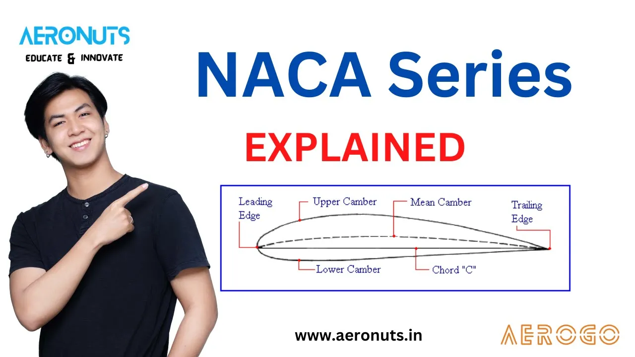
The NACA 4-digit airfoil series is defined by three geometric parameters: maximum camber (m) as a percentage of chord length, chordwise position of maximum camber (p) as a fraction of chord length, and maximum section thickness (t) as a percentage of chord length. The airfoil shape is constructed by first defining the mean camber line using piecewise equations, then calculating the local slope angle θ at each point, and finally adding the thickness distribution perpendicular to the camber line using trigonometric relationships. The thickness distribution follows the equation Yt = 5t[(0.2969√x - 0.1260x + 0.3516x² - 0.2843x³ + 0.1015x⁴)] for a 20% thickness airfoil, scaled by the desired thickness percentage. The upper and lower surface coordinates are obtained by offsetting from the camber line using the formulas: x_upper = x - Yt × sin(θ) and y_upper = y_camber + Yt × cos(θ), while x_lower = x + Yt × sin(θ) and y_lower = y_camber - Yt × cos(θ).
NACA 4-Digit Airfoil Equations: Camber, Thickness & Coordinate Generation
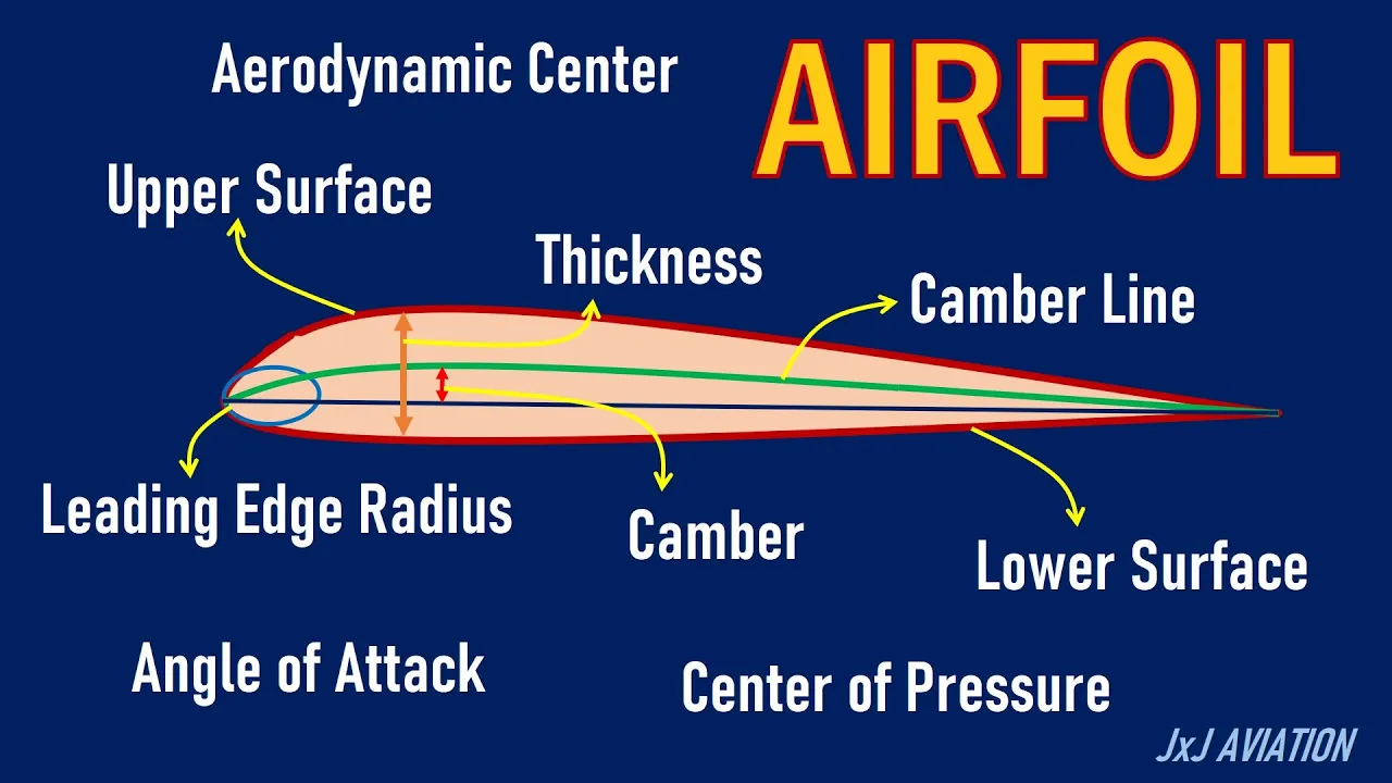
Added:hey everyone in this video I'm going to be going over the nacka four-digit air foils first I'll go through uh just a general overview of the air foils and then after that I'll go through a mathematical description of them uh in a subsequent video I'm going to show you how to code up your own program to calculate different uh data points for these air foils that you can export as a as a text file for use and whatever you want to do with it uh so the nacka 4digit air foil uh is a geometric description of an air foil and there are two primary variables that describe uh the geometry of this air foil the first is the mean camber line shown in blue and you can see that here and then the second is a thickness distribution above and below the mean camber line shown in these green dotted lines here uh my picture is not to scale because the upper and the lower on one of these dotted lines should be equal uh C is the cord length of the air foil I have a video on cord length that I'll post in the description uh if you want to take a look at that and so you'll see in the literature or just in anything that you read that uh the general formula for the air foil looks like this it's a NAA something something something something uh and you can see that it's either like a 2412 or A2 might be something that you've that you've seen uh quite often so now let's go through what each of these uh terms mean so the m is the maximum camber uh as percentage of the cord so in this case for the 2412 that means that it's uh 2% so the maximum camber of the air foil the maximum camber may be like right here for this air foil that's 2% of the cord length uh the second term is p which is the chordwise position of the maximum camber and that for this case here it's p over 10 so this four that's not 4% that's actually 40% so that means that the maximum camber occurs uh 4/10 of the 4/10 of the way back from the Leading Edge of the cord of the cord length so in this case here if the maximum camber is like right about here it looks like this one might actually be five in this in this p position and then the XX here that's one number so this 12 is one number it's not one two it's 12 and that's the maximum section thickness uh as percentage of the cord so in this case the 12 here and the 12 here I guess um means that it's uh has a 12% maximum thickness of the air foil as a function of the cord length the first thing we need to do is find the mean camber line which is defined by the m and the p terms in the four-digit air foil designation so in the npx X designation uh this is a plot of the mean camber line so without any of the thickness applied to the air foil yet and I'm going to assume a chord length of one length unit so meter feet because we can always multiply by a certain cord length later on so this cord length here is going to be one the Leading Edge here is that located at x equals 0 and the trailing EDG is at x equals the chord length or one uh this P if you recall from the previous image before uh is the location along the cord of the maximum uh camber so these are the two equations that specify this blue line here the top one is used uh when you're going from the Leading Edge to point p and the bottom one is used from point P to the trailing Edge uh if one thing to note is that if you have a symmetric air foil so such as like A2 the first two numbers the m and the P are both zeros so if you look at these equations here for the uh y coordinate the if you plug in m is equal to Z here you'll get a y-coordinate of zero uh for both of these equations for the entire length of the of the air foil which means that for every X it'll be the y coordinate will be at zero which means you'll just get a flat line here indicating that there's no camber so now that we have the mean camber line equations the next thing we need to do is to find the uh derivative of the mean camber line equations so if we have these two equations from the previous white board we just take the derivative with respect to the x coordinate and you get these two expressions so for the front half well front up to p and then from P to the end of the the uh cord so in this picture over here this is the main camera line I'm going to zoom in on this little portion right here and this is the green portion here I'm going to draw take a point in black and draw a line tangent to it and for a certain distance that we move in X along the air foil or along the cord line we need to move a certain distance y to get to the next point and this angle here th Theta is defined as the inverse tangent of this change in the y-coordinate over the change in the x coordinate uh which is just this equation here so the Theta you can Define as the inverse tangent of this or this equation depending on where you are on the air foil and so the question is why do you need to do that uh if you take this mean camber line you need to add some thickness to the air foil and I'll go through the thickness Distribution on the next whiteboard um and you might think oh I'll just add it vertically to the point where I'm at so if I'm add an X point along the along the air foil I'll just add the thickness up and down but what you actually need to do is you need to add the thickness perpendicular to the mean camber line which is where this Theta turn comes into play so once you know the slope you can uh add the thickness uh perpendicular to this mean camber line now that we have the mean camber line which you can see in blue here we need to add the thickness distribution to that air foil here seen in the dashed green lines uh so this is the equation for the thickness so Y subt is a thickness distribution it's given by this equation that has these coefficients a0 A1 A2 A3 A4 for uh each of these X terms here and the X terms are taken into account the distance from the Leading Edge to the trailing Edge uh these coefficients are given down here and they're defined for a 20% thickness air foil and the way that it that you can account for the change and thickness uh given here that you defined for your air foil is this front term here which takes into account that XX term uh the one thing to note is that this A4 coefficient here there's two of them one of them is for uh an open trailing Edge or a finite thickness trailing Edge and another one is for a Sharp trailing Edge it's important to note that this YT is a half thickness in the sense that it's a thickness above and a thickness below it doesn't take into account the entire thickness so what you need to do is you need to add this thickness both above the mean camber line perpendicular to the mean camber line and Below perpendicular to the mean camber line so now we have the mean camber line and we also have the thickness distribution of the air foil so we can now Define the overall coordinates of the air foil that we want to specify so here we have the mean camber line and here I have the thickness distribution and what we're trying to find is this particular point it's a black circle and I'm calling this one CU this is the upper surface here I'm calling this X U and Y U for the lower surface I call it x sub L and and Y sub l so if I take this I'm going to drop a line over perpendicular to the y- AIS here like this and then you can see it goes down to the to the point on the main cam line so I'm going to blow that up here you can see that this green line is still the thickness distribution or Y subt and then we have this distance Alpha and the distance beta that we're going to need to Define where this point is in space based off of the camber line and the thickness distribution so we remember Theta from before and if we specify this distance as Alpha and that's as beta we can say from trigonometric uh principles that the S of the Theta is equal to the alpha over YT and beta is equal to the or cosine of theta is equal to Beta over YT and if we rearrange we get expressions for Alpha and beta in terms of YT and Theta which we both know so we can Define points on the upper surface and the lower surface looking at the upper surface here the x of the at a certain X distance so we're at a certain X Point here we know that the X point if it's sloping up like this the X Point since we have to since we have to draw the uh thickness perpendicular to to the mean camber line it's going to be less than this x point so we have this x upper is equal to the X Point minus the thickness YT time the S of the Theta like this and it's a sign here and you might wonder oh well what happens when it's when the the trailing Edge when it's sloping down well that is going to be even though there's a minus sign here it's going to be taken into account in the S SN of the sin Theta term in the Y upper we're going to have y of the camber line so at a certain uh Point here we're at a certain distance above the zero line the zero chord line already so we need to take that y of the camber line and then we need to add the YT cos Theta or the beta distance up and this is always going to be uh positive because on the upper surface you're always going to be adding and then similarly for the lower surface we have the x sub l and y sub L and they're similar but they're just switched with these signs here and uh and they give you the points that are on the bottom uh or the lower surface of the air foil there so the one thing we need to note about these equations here is what happens when we have a symmetric air foil so when we have a symmetric air foil uh if you recall from before or the angle Theta is going to be zero so we need to plug in the Theta is equal to Z into these expressions and see what we get and if you do that you can see that at s of zero you get a zero so this term goes away which means that all along the air foil you every single X point is at its actual XO which makes sense if you look at the this is the camber line of a symmetric air foil it's a straight horizontal line if I've drawn that correctly and that means that there's no slope so every single point that you draw if you take this x point the thickness is going to be up a certain point at that exact X point and there's it's not going to be moved either left or right because of the slope and now if we plug in zero to this cosine term this is a one so we have the Y camber plus the Y thickness so the Y camber we're at this point because it's a horizontal line so it's at zero and we need to add the thickness and we're just adding the thickness up and so it checks out that these equations work for a symmetric air foil like A2 or whatever you want I'm going to be going over in the next video about how to program a mat lab code that will give you uh the air foil shape based off of what you input so you can input like a NAA 2412 or naa2 and it'll give you the coordinates for the air foil based off of how many grid points you put in there Etc so thanks for watching
Up Next

How to Set Up and Control Aerofoil Shapes in a Wind Tunnel
@MatrixTSLtd
145 views•2023-04-21

Ultrasonic Transducers: Resonant Frequency Measurement and Horn Design
@imajeenyus42
229.9K views•2017-02-22

DIY Background Oriented Schlieren Imaging: Step-by-Step Guide
@JoshTheEngineer
29.2K views•2019-10-21

How a Student's Question Saved a NYC Skyscraper from Collapse
@veritasium
22.8M views•2025-04-26
Related Study Plans & Knowledge Roadmaps
Structured learning paths in Engineering