An air jet loom is a high-speed weaving machine that inserts weft yarn through the warp shed using compressed air propulsion; the process involves opening the weft accumulator, activating the main nozzle to drag the yarn into the shed, sequentially firing relay nozzles to propel the yarn across the width, closing the brake, and using a stretch nozzle to secure the tail, followed by the beating-up mechanism that compacts the weft into place and a filling cutter that trims excess yarn, with modern machines incorporating sensors and cameras for quality control.
Air Jet Loom Working Principle and Weft Insertion Mechanism
Added:Deep Dive
Basic principles of weaving, including the core concepts of warp, weft, shedding, picking, and beating-up.
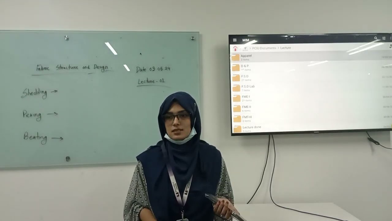
Fabric Structure & Design | Lecture-01(DIP) | Textile | Israt Khandaker | University of Scholars
198
The three primary motions essential for fabric production are shedding, picking, and beating up. Shedding divides warp yarns into two parts to create a gap (shed) for weft insertion. Picking inserts the weft yarn through this shed using a shuttle. Beating up adjusts the weft yarn to the cloth fall to compact the fabric. These motions work together to create woven fabric structure.
Click to watch →

Weaving Process in Textile Industries - Step by Step Explanation
207.3K
Weaving can be summarized as a repetition of three primary motions of the loom: shedding (where the warp threads are separated by raising or lowering heddle frames to form a clear space where the shuttle can pass), picking (where the weft or pick is propelled across the loom by hand or by a shuttle), and beating up or battening (where the weft is pushed up against the fell of the cloth by the reed).
Click to watch →

Weaving, basic weaves and standard fabrics: process of weaving eng
263
Weaving is a fabric production process performed on a loom where warp yarns are first prepared by filling empty bobbins with yarn using a winding machine, then mounted on a creel and led to the warp beam, which is completely filled by repeating the process 12 times to create a 400-meter section; the weaving process involves three primary motions—shedding (splitting the warp sheet into two parts using heddle shafts), picking (passing weft yarn across through the shed), and beating (placing the weft yarn at the cloth fell)—along with two secondary motions—let-off (controlling warp yarn release from the beam) and take-up (regulating cloth pickup and wrapping on the cloth roll).
Click to watch →

WEAVING OPERATION WITH THE COUNTER MATCH LOOM. ||STANDARD TREADLING LOOM ||(SDG)
220
Weaving involves three primary motions that work together to create fabric. First, shedding separates warp threads into two sheets by raising and lowering heddle shafts, creating an opening called the shed. Second, picking moves the shuttle through this shed to carry the weft yarn across the fabric. Third, beating pushes the weft yarn toward the fell of the fabric using the reed, packing the threads tightly to form the fabric structure. These three motions are coordinated through the treadle system, where the weaver alternates leg position to control the heddle shafts and create the weaving pattern.
Click to watch →

LT GRADE HOME SCIENCE PRACTICE SET HOME SCIENCE LT GRADE NET/JRF TGT PGT PRACTICE SET BY JYOTI MA'AM
24.7K
The three primary motions in weaving are shedding (creating the path for the weft thread), picking (passing the weft thread through the shed), and beating-up (pushing the fabric to maintain density). These three motions work together to create fabric during the weaving process.
Click to watch →
Deep Dive
Fundamental concepts of fluid dynamics and pneumatics, particularly how compressed air behaves and generates velocity through nozzles.
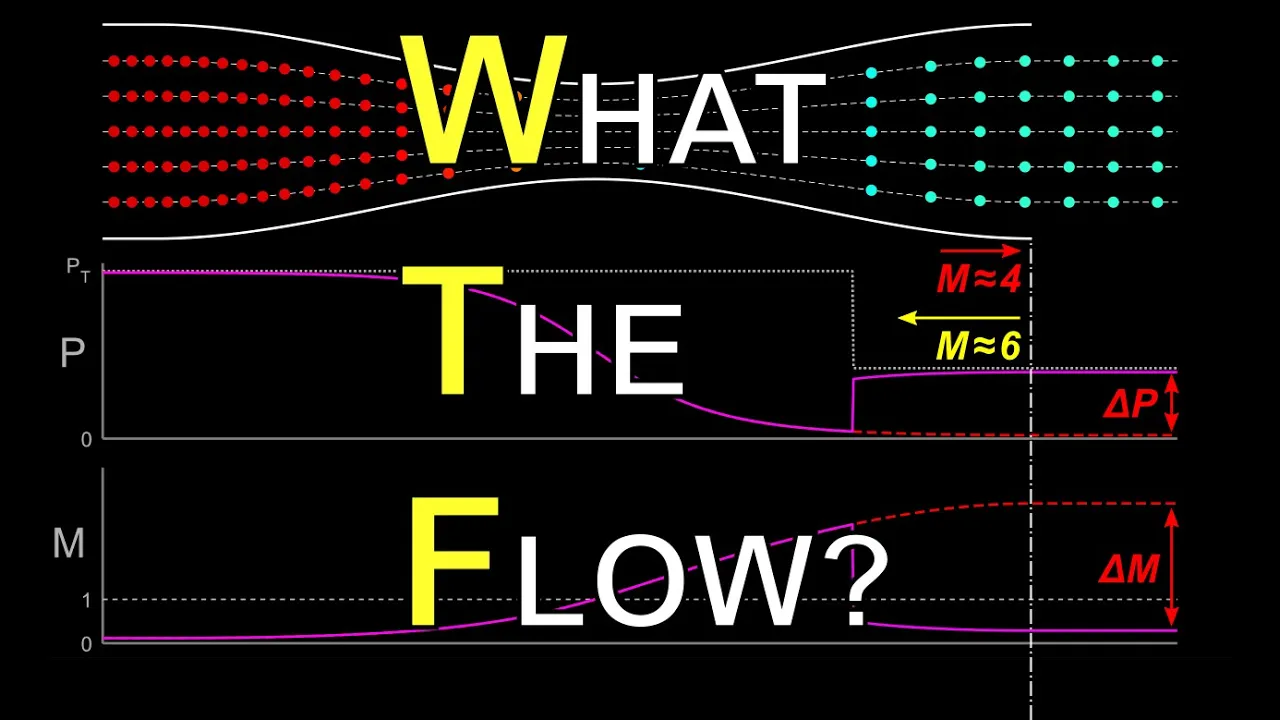
Supersonic Nozzles - What happens next will SHOCK you!
77.2K
This section establishes foundational concepts for understanding converging-diverging nozzles. Key principles include: (1) Fluid acceleration/deceleration depends on pressure gradients—lower downstream pressure accelerates flow while higher pressure decelerates it; (2) Nozzle exit pressure must match environmental pressure, with shock waves or expansion fans enforcing this condition; (3) For compressible flows, total pressure and total temperature replace total energy as conserved quantities; (4) The Mach number is the ratio of fluid speed to local speed of sound; (5) Below Mach 0.3, flows can be treated as incompressible. These principles form the basis for understanding how nozzles manipulate fluid velocity through area changes.
Click to watch →
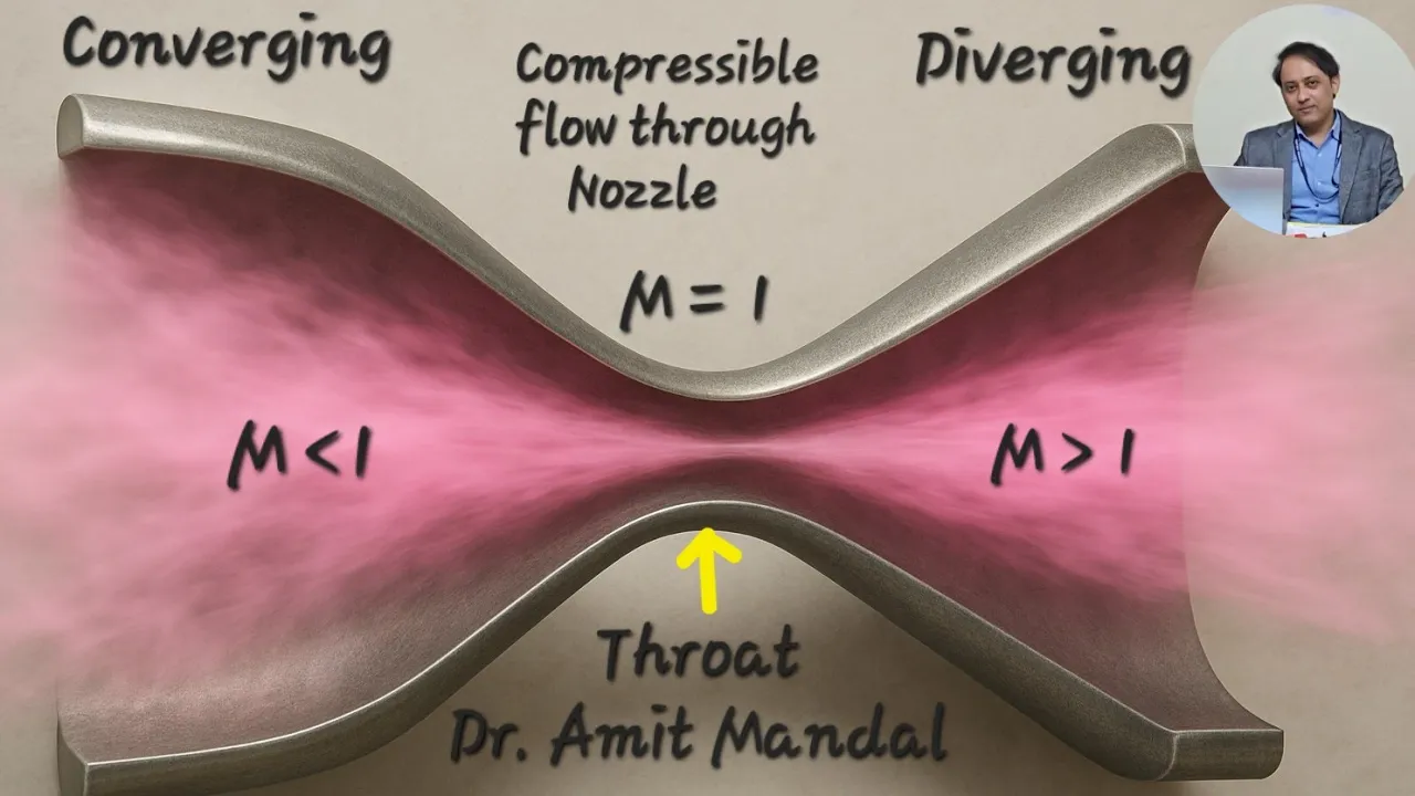
Compressible flow through Nozzle
109.7K
A nozzle converts fluid energy into velocity by decreasing enthalpy or head. For incompressible fluids, head drops increase velocity; for compressible fluids, enthalpy drops convert to kinetic energy. The continuity equation ρ₁A₁C₁ = ρ₂A₂C₂ ensures mass conservation. The local Mach number M = C/√(γRT) classifies flow regimes: subsonic (M<1), sonic (M=1), and supersonic (M>1). Converging nozzles accelerate subsonic flow to sonic velocity but cannot produce supersonic flow. Diverging nozzles are required for supersonic acceleration. A converging-diverging nozzle combines both sections to achieve supersonic acceleration from subsonic inlet conditions.
Click to watch →

Hermann-Thormilten-Schule Lippetal
3.1K
This video demonstrates fundamental principles of fluid dynamics and compressed air mechanics. Key concepts include: (1) Air is compressible while water is not, meaning air can be forced into smaller volumes under pressure; (2) Compressed air can be used to propel liquids through nozzles, as seen in spray bottles and rocket mechanisms; (3) When compressed air is released, it creates pressure that forces water out in a stream; (4) The compressibility difference between air and water is essential for understanding how pressurized systems work. These principles apply to everyday devices like spray bottles and more complex propulsion systems.
Click to watch →

Neumática producción y transporte de aire comprimido SMC Perú/Production,transport of compressed air
1.3K
Pneumatics (from Greek 'neumatikos' meaning wind) is the movement of objects using compressed air. Two fundamental concepts govern pneumatic systems: flow rate (volume of air per unit time, measured in L/min or CFM) and pressure (force per unit area from air molecules). Higher pressure means more molecules exerting greater force on container walls. Pressure applies equally in all directions, maintaining constant pressure in closed tanks. Larger pipe diameters increase air displacement capacity.
Click to watch →
El aire comprimido. Tecnología 4º ESO. Bloque neumática e hidráulica #3.
2.4K
This section introduces the physical principles of pneumatics, focusing on compressed air as the working fluid. Key advantages include abundance, ease of transport and storage, non-contamination, safety, temperature resistance, and ease of speed/force regulation. Air composition is 78% nitrogen, 21% oxygen, and 1% other gases, with properties of high compressibility, low viscosity, and complete container occupation. Compressed air is atmospheric air enclosed under pressure greater than atmospheric, performing work when expanded—similar to a spring. The ideal gas law (PV = nRT) governs its behavior, relating pressure, volume, and temperature in closed systems where moles remain constant.
Click to watch →
Deep Dive
Familiarity with traditional mechanical weft insertion methods, such as shuttle and rapier systems, to understand the transition to shuttleless technology.

Basic Function of the Weaving Loom /Filling Insertion #weaving #weavingloom #weavingmachine #fabric
8.8K
Three mechanical systems insert filling yarn through physical carriers. The shuttle loom, first power loom, uses a boat-shaped device carrying its own yarn supply at 150-200 ppm. Rapier systems grip yarn and carry it across: single rigid uses solid rods requiring external storage; double rigid splits work between two rapiers for faster insertion; double flexible uses lightweight tapes/coils for 850 ppm; double telescoping telescopes length for reduced width but limited to 350 ppm. Projectile systems use bullet-shaped carriers without self-contained yarn, fired across the shed for rapid pick insertion.
Click to watch →

Type of Weft Insertions in weaving loom
613.6K
Weaving looms use five main types of weft insertion systems: shuttle (boat-shaped device carrying yarn, 150-200 picks/min), rapier (gripping yarn across the shed with four variants: single rigid, double rigid, double flexible, and double telescoping, achieving up to 850 picks/min), projectile (bullet-shaped carrier propelled across the shed), airjet (high-pressure air stream achieving 1,000-1,200 picks/min), and waterjet (using water instead of air, requiring hydrophobic fibers). Each system offers different advantages in terms of speed, versatility, floor space requirements, and yarn compatibility.
Click to watch →
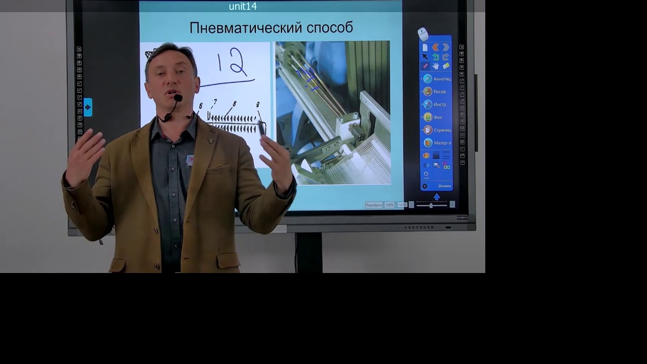
Лекции SS. Ткацкие станки. Прокладывание уточной нити в зев. Часть 2.
2K
The five main weaving operations are: shed formation, weft insertion, weft beating-up, weft take-up, and cloth take-up. Weft insertion methods evolved from manual shuttle (челнок) to modern automated systems. The shuttle method, the oldest technique, uses a shuttle box with a bobbin moving back and forth through the shed. The micro-rapier method uses a small device (30g) with clamps that grip the weft thread, strike through the shed, and deposit it. The air jet method uses two hollow tubes transmitting weft thread by air pressure at 18-20m/s. The pneumatic method uses air streams from nozzles to propel weft thread, with multiple nozzles enabling different weft threads for complex patterns. Relay nozzles prevent thread loss. Major manufacturers include Temex (Belgium), Toyota (Japan), and French companies.
Click to watch →

Rapier shuttleless looms | Construction and working of Rapier looms| Rigid & Flexible Rapier
11.5K
A rapier shuttleless loom is a modern weaving machine that inserts weft yarn using flexible or rigid rapiers (grippers) instead of traditional shuttles. The loom consists of key components including a warp package, accumulator, tensioner, web detector, thread guides, and the rapier mechanism. In single rapier operation, one gripper extends from the loom, picks up the weft yarn, carries it across the shed, inserts it into the fabric, and returns. In double rapier operation, two grippers approach from opposite sides, meet at the center to transfer the weft, and then return separately. The flexible rapier system uses a housing to contain the curved gripper during movement, while rigid rapiers maintain a straight path. This shuttleless design eliminates the need for shuttle-based weft insertion, enabling faster and more versatile fabric production.
Click to watch →

An introduction about shuttleless weaving method( non-conventional weft insertion system)
1.6K
Non-conventional weft insertion systems are modern textile weaving technologies that replace traditional shuttle-based methods with alternative mechanisms like projectiles, rapiers, air jets, and water jets to insert weft yarns, offering advantages such as reduced manufacturing costs, increased loom revolutions per minute, elimination of selvedge wastage, and the ability to produce multi-colored fabrics efficiently.
Click to watch →
Deep Dive
Basic physical properties of textile yarns, specifically how yarn density, hairiness, and twist affect its aerodynamics.

Fios além da espessura: o que mais importa?
473
Yarn twist and ply affect density and yardage. More twist creates denser, firmer yarns with less yardage per weight. Less twist creates lighter, airier yarns with more yardage. Single ply yarns have one strand, while multi-ply yarns twist multiple strands together, increasing density. Fiber composition also affects weight—merino wool is lighter than cotton, so merino yarns have more yardage. Dense constructions like braids create heavier fabrics, while open constructions create lighter, airier fabrics.
Click to watch →

Fixing my Overspun Yarn by Re-spinning It!
37.4K
The amount of twist directly affects yarn properties: high twist yarns are tighter, narrower, more compressed, and hold fibers together more tightly; low twist yarns are fluffier, looser, bulkier, contain more air, and feel softer. High twist yarns are better suited for warp threads in weaving because they resist abrasion and provide strength, while low twist yarns are preferable for garments worn next to the skin due to their softness and loft.
Click to watch →
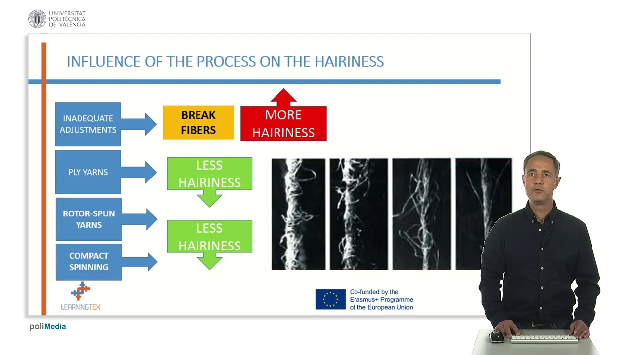
Hairiness of yarns | 11/87 | UPV
194
Yarn hairiness, defined as the number of fibers protruding from a yarn's axis, is an undesirable property that has become increasingly problematic with high-speed looms and knitting machines; it is influenced by fiber parameters such as length (longer fibers reduce hairiness), fineness/stiffness (thicker/rigid fibers increase hairiness), and breaking strength (lower strength increases breakage and thus hairiness), as well as manufacturing factors including spinning process adjustments and the inclusion of waste materials; technologies like rotor spinning and compact spinning effectively reduce yarn hairiness, while ply yarns generally show lower hairiness than single yarns.
Click to watch →

YARN TWIST | TYPES & FUNCTION OF YARN TWIST | EFFECTS ON YARN PROPERTIES | TEXTILE2020 | HINDI
34.8K
Yarn twist serves three primary functions: binding fibers together, providing strength through inter-fiber friction, and creating a round yarn shape essential for quality fabric. Twist significantly affects fabric properties including pilling tendency and tension performance. Fine fibers with long staple length exhibit less pilling because they twist more effectively and bind better. Short fibers with high twist tend to pill more due to ineffective binding. Higher twist levels improve tension properties by distributing stress more evenly through increased fiber friction. These relationships between twist and fabric properties are fundamental to textile quality control and manufacturing decisions.
Click to watch →

Episode 92 Live: Finished Objects!
1.9K
Yarn density is directly related to twist in the spinning process. The host compares two yarns of the same fingering weight but different densities. The older yarn (spun in 2016) was tightly spun with many twists in both singles and plying, resulting in a dense, heavy fabric. The newer yarn (spun in 2017) was spun with gentler twists, resulting in a lighter, airier fabric despite being the same weight. This demonstrates that yarn density is controlled by twist amount, not just yarn weight classification.
Click to watch →
Prerequisite Knowledge
- Concept 01Basic principles of weaving, including the core concepts of warp, weft, shedding, picking, and beating-up.
- Concept 02Fundamental concepts of fluid dynamics and pneumatics, particularly how compressed air behaves and generates velocity through nozzles.
- Concept 03Familiarity with traditional mechanical weft insertion methods, such as shuttle and rapier systems, to understand the transition to shuttleless technology.
- Concept 04Basic physical properties of textile yarns, specifically how yarn density, hairiness, and twist affect its aerodynamics.
Subsequent Learning
- Step 01Advanced synchronization and timing control of main and relay nozzles using programmable logic controllers (PLCs).
- Step 02Energy efficiency and consumption optimization of compressed air systems in high-capacity weaving mills.
- Step 03Analysis of weaving defects specific to air jet looms, such as short picks, weft bucking, and automated sensor-based fault detection.
- Step 04Comparative analysis of shuttleless weaving technologies (air jet vs. water jet vs. rapier) regarding material suitability and production economics.
Airjet Basics
Cycle & Tech
Airjet Basics
0:00Playing Section
- 1
Explains airjet loom speed and suitability for high-volume fabric production.
- 2
Describes core mechanism using compressed air to propel weft yarn through warp shed.
- 3
Highlights multiple nozzle system and profile reed for efficient weft insertion.
The Energy and Versatility Constraints of Air-Jet Weaving
While air-jet looms excel in speed and productivity, reaching up to 2000 picks per minute, critics and textile engineers highlight significant drawbacks that make alternative insertion methods, like rapier and projectile systems, more viable. The primary criticism of air-jet looms is their high energy consumption; generating compressed air requires immense electrical power, leading to higher operational costs and a larger carbon footprint. Furthermore, air-jet looms lack versatility in yarn handling. They struggle with heavy, highly irregular, or delicate fancy yarns because the air stream cannot reliably control these materials. In contrast, rapier looms offer precise, positive mechanical control over the weft yarn, allowing them to weave almost any yarn type or fabric weight, including technical textiles and complex multi-color patterns. Projectile looms, while slower, offer superior fabric width capabilities and lower energy consumption per unit of fabric. Therefore, the choice of weaving technology is a trade-off between the sheer speed of air-jet insertion and the energy efficiency, versatility, and precision offered by mechanical insertion methods.
Deep Dive
Advanced synchronization and timing control of main and relay nozzles using programmable logic controllers (PLCs).
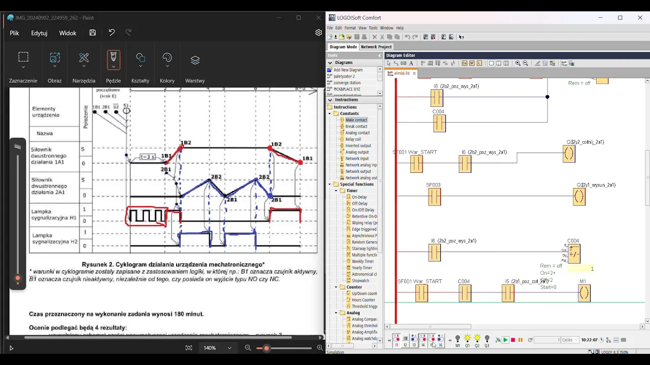
Egzamin zawodowy ELM.06 - Technik Mechatronik (Analiza zadania + Programowanie - PLC SIEMENS LOGO)
6.1K
This section covers the implementation of timer-based delays and position-based control in the PLC program. A timer (T02) creates a 3-second delay before the first cylinder movement begins. Cylinder movements are controlled based on position sensor feedback. The first cylinder extends when the start condition is met and the timer expires. The second cylinder only starts extending after the first cylinder has reached its fully extended position (detected by sensor 1B2). This ensures sequential operation where each cylinder's movement depends on the completion of the previous cylinder's movement.
Click to watch →
25년 설비 보전기사 공개문제 공압 1번 (화질개선) 재촬영
426
Timing control in PLC systems uses timers to introduce delays between operations. A timer is connected to the output of a relay, and it delays the activation of the next step—for example, waiting 3 seconds after cylinder A completes forward motion before allowing cylinder B to start. The timer output connects to the next relay coil, which then activates the corresponding output. Speed control in pneumatic systems uses flow control valves (meter-out configuration) to regulate air flow rate entering or exiting cylinders, controlling cylinder speed. The valve must be oriented correctly (arrow direction indicates flow direction) and properly connected to the cylinder. For forward motion, the valve connects to the inlet port; for reverse motion, it connects to the outlet port. Speed can be adjusted by changing the valve's opening position.
Click to watch →

UD4_CID (4ª sesión) Automatización con relé programable
243
PLC programming with double pulse and time-based automation: (1) A double pulse (pulsación larga) is used to reset the counter, (2) The reset is triggered by holding the start signal for a specified duration (e.g., 5 seconds), (3) A timer (retardo a la conexión) is used to detect the double pulse, (4) When the timer expires, the reset input receives a 1, (5) A weekly clock (reloj semanal) is used to control operations based on time of day, (6) The clock can be configured for different days of the week and generate signals at specific times for specific durations, (7) This allows automated scheduling of operations without manual intervention. PLC programming with impulse relay: (1) An impulse relay (relé de impulsos) is used for on/off control, (2) The relay activates when the input is active and deactivates when the input is inactive, (3) A timer (retardo a la desconexión) ensures the load is turned off after a specified duration, (4) Multiple impulse relays can be used to control multiple plants, (5) This allows centralized control of multiple independent systems.
Click to watch →

Introduction to Programmable Logic Controllers (PLCs) (Full Lecture)
212.3K
A Programmable Logic Controller (PLC) is a ruggedized computer designed for industrial environments that replaces traditional hard-wired relay-based ladder logic systems; PLCs offer superior reliability, flexibility, cost-effectiveness, and advanced data processing capabilities through reprogrammable software that controls actuators like motors and valves, with key components including the CPU, input/output modules, power supply, and communication ports, and they execute programs sequentially using scan time rather than in real-time.
Click to watch →

뱅가의 전기놀이터 전기기능장 PLC 2과제 구독자 요청 문제 풀이 앤디님 정렬후 정,역방향 갯수제어
110
This segment covers output control and timing synchronization in PLC programming. The system uses relay outputs (M1-M5) to indicate movement positions. Proper timing synchronization is critical when multiple operations occur simultaneously, such as counter increment and direction change. The system must ensure direction changes occur at the correct moment relative to counter values. The implementation includes output mapping for each movement position and timing adjustments to prevent operational conflicts.
Click to watch →
Deep Dive
Energy efficiency and consumption optimization of compressed air systems in high-capacity weaving mills.

Module 7 Session 2: Energy Efficiency in Textile Utilities
191
Compressed air systems operate at only 10-13% efficiency, with most energy lost as waste heat. Heat recovery becomes economically viable in colder climates (1-year payback) versus warmer regions (2-year payback). Multi-compressor systems with intelligent VFD control can achieve 30-50% energy savings compared to manually controlled systems. Key optimization strategies include proper sequencing to prevent simultaneous compressor cycling, regular leakage detection during no-demand conditions, and pressure drop analysis to identify areas requiring receiver tanks. Small systems may not justify heat recovery investments, making large industrial applications like weaving and spinning most suitable for these improvements.
Click to watch →

How energy efficiency can help manufacturers avoid and electrical upgrade and save serious $$$
312
Compressed air systems represent a major energy consumption area in industrial facilities, with total cost of ownership dominated by energy use (80%). Typical sites allocate 3-7% of electricity budgets to compressed air, though exceptional cases reach 40%. Analysis of over 30 systems reveals more than half operate at twice ideal efficiency levels. Effective optimization requires measuring specific energy consumption (energy input/air output) and implementing both supply-side and demand-side improvements. Supply-side strategies focus on proper compressor sizing and sequencing, while demand-side actions include leak management, replacing compressed air vacuum pumps with electric alternatives, and optimizing timer-based controls for dehumidification systems.
Click to watch →

Marubeni Focusing Spinning & Weaving Sector in Bangladesh | M/C Supplier | Caue Suguimati Interview
155
Reducing air pressure in weaving machines leads to significant electricity savings on compressors. Companies can calculate and demonstrate to customers how much electricity can be saved per month or year by reducing air pressure. This efficiency calculation helps customers understand the economic benefits of upgrading to more efficient machinery.
Click to watch →

Ahorro energético en sistemas de aire comprimido
1.6K
Compressed air systems waste energy through three primary sources: air leaks (30% of consumption), artificial demand from generating higher pressures than needed (10% waste), and improper use including cleaning applications and inefficient cooling (10% waste). Together, 50-60% of generated air is wasted. Energy consumption represents 63% of total system costs over 5 years, with approximately 31.5% wasted through inefficient generation and distribution. Companies can achieve 15-30% energy savings through proper audits and maintenance. For a plant spending $1,350 annually, this represents $405 in potential savings. Larger facilities with 120 HP compressors spending $32,000 annually can save $9,720 through systematic optimization.
Click to watch →

Webinar: Compressed Air System Demand - Needs v Actual Usage
16.9K
Compressed air systems represent significant energy waste opportunities with potential savings exceeding 50%. Five key optimization strategies exist: leak detection (10-50% savings), artificial demand reduction (5-50%), inappropriate use elimination, peak load management, and system pressure reduction (4.5-9% per bar). A typical plant analysis reveals that 25% of compressed air goes to leaks, 25% to valves/cylinders, 25% to pneumatic conveying, 10% to vacuum generators, and 10% to bearing cooling. Artificial demand occurs when equipment operates at higher pressures than required, since flow is directly proportional to absolute pressure. Regulating from 7 bar to 5 bar achieves 25% reduction. Pneumatic conveying often uses excessive pressure; reducing from 7 bar to 3 bar cuts air consumption by 50%. Substituting with dedicated blowers achieves 75% savings. Reducing system pressure immediately reduces leak losses without fixing individual leaks: 7.5 bar to 6 bar eliminates 17.7% of leaks. Common inappropriate uses include bearing cooling, tank agitation, air lances, cleaning, vacuum generation, and drying. Vacuum generators offer 75% savings over direct compressed air vacuum generation. Vortex amplifiers provide 20:1 amplification for 80-90% reduction in spot cleaning and dust removal applications.
Click to watch →
Deep Dive
Analysis of weaving defects specific to air jet looms, such as short picks, weft bucking, and automated sensor-based fault detection.

Defects in fabric #airjetloomfabricdefects#fabricdamages
1.1K
Fabric defects in airjet loom weaving are categorized into human errors (12 out of 40 points) and machine errors, including warp beam issues, incorrect color packages, pattern errors, denting/drawing order mistakes, broken/slack/pick defects, contamination marks, temple marks, and various structural irregularities like slubs, thin/thick places, and shade variations.
Click to watch →

Inside the Sheep Wool Processing Factory: How Sheep’s Fleece Becomes Luxury Fashion|Complete Process
19.6K
The weaving system transforms threads into textile structure. Before weaving, automated sensors measure tension, humidity, and density in climate-controlled environments (68°F, 65% humidity). Warping involves threading thousands of strands through needles forming the fabric foundation—for 1-meter-wide fabric, this might involve 2,000 individual threads aligned to fractions of a millimeter. Modern AirJet looms propel weft threads at over 60 mph, completing over 800 picks per minute (more than 13 insertions every second). Fault sensors monitor every movement, halting instantly if yarn breaks.
Click to watch →
Weft insertion system in Air jet loom or Water jet loom , fabric manufacturing process
1.6K
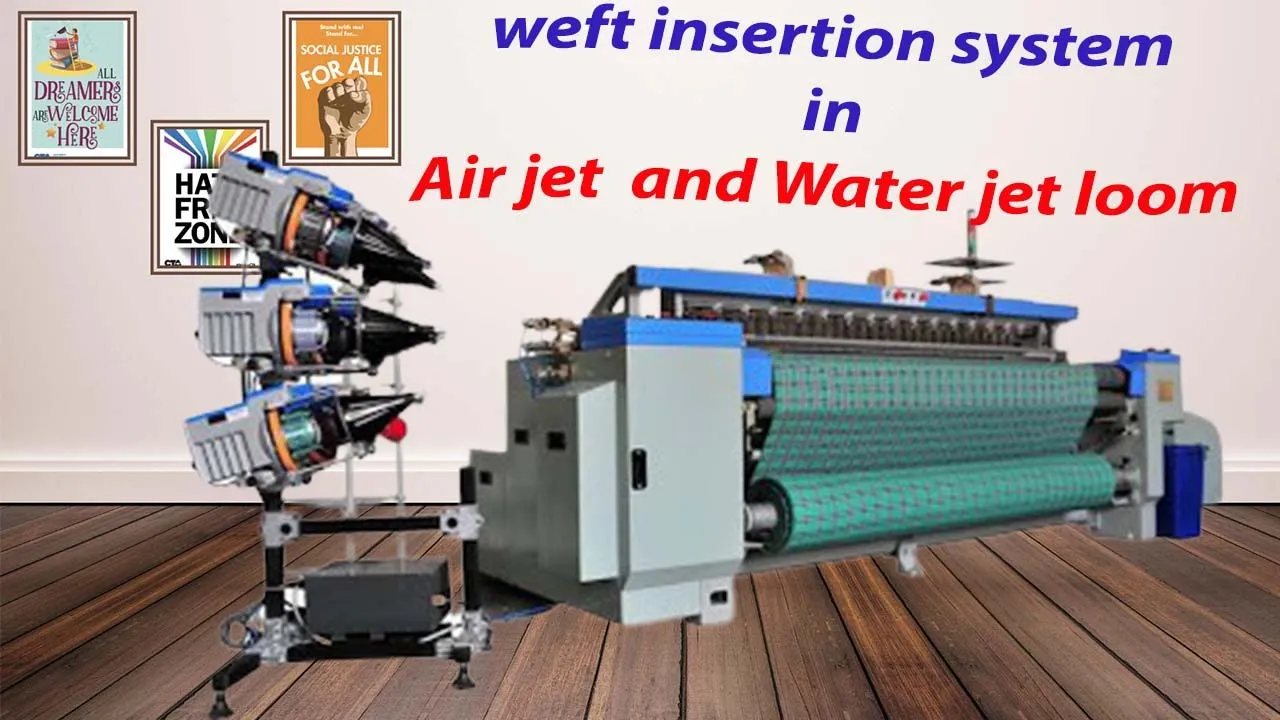
The air jet loom weft insertion system uses compressed air to accelerate and control weft insertion. Weft is stored on packages in the weft creel, with measuring drums controlling the amount stored and length of each pick. When the stopper pin releases, tandem nozzles pull weft from the measuring drum. The main nozzle on the reed profile supplies air to insert weft into the open shed and reed air tunnel, while also accelerating weft across the reed width. Relay nozzles across the reed width control weft in the reed tunnel during insertion. When weft reaches the right side of the reed, additional relay nozzles or an optional stretch nozzle secures the weft under tension.
Click to watch →

weft picking or passage in AirJet loom in Hindi ,Study of airjet loom
1.9K
The weft picking process in an AirJet loom involves the systematic passage of weft yarn through multiple components including bobbin packages, guides, tensioners, doffers, magnet pins, balloon breakers, nozzles, reeds, and cutters, with sensors monitoring yarn position to ensure proper fabric formation and prevent breakage.
Click to watch →

Air jet loom weaving Process, Speed and types of machine
342.3K
An air-jet loom is a shuttleless weaving machine that propels weft yarn through the warp shed using a jet of air. The system consists of a main nozzle, auxiliary (or relay) nozzles, and a profile reed. The main nozzle provides the initial propulsive force to launch the weft yarn into the shed. As the yarn travels across the width of the loom, electronically controlled relay nozzles sequentially release booster jets of air to maintain momentum and ensure the yarn reaches the opposite side. These relay nozzles are positioned along the channel to sustain air pressure and guide the yarn accurately. The profile reed helps position and beat the weft yarn into place after insertion. This method eliminates the need for a shuttle, enabling higher weaving speeds and reduced mechanical wear. The maximum effective weaving width for air-jet looms is approximately 355 cm, limiting their use to medium to wide fabric production. The system relies entirely on compressed air for weft insertion, making it suitable for synthetic and smooth yarns that can withstand high-speed air propulsion without fraying. Air-jet weaving is widely used in industrial textile manufacturing for high-volume production due to its speed and efficiency compared to traditional shuttle looms.
Click to watch →
Deep Dive
Comparative analysis of shuttleless weaving technologies (air jet vs. water jet vs. rapier) regarding material suitability and production economics.

Introduction to Shuttle less Looms | Advance Weaving | Types of Shuttle less Looms | textile2020
12.8K
Shuttleless looms represent a fundamental advancement over traditional shuttle looms by eliminating the shuttle device for weft yarn insertion. Shuttle looms use a wooden shuttle that travels between shuttle boxes, creating limitations including friction from shuttle weight, fixed passage width requirements, vibration from overpick/underpick motions, and limited force application. Shuttleless looms overcome these limitations through alternative insertion methods: air jet (compressed air), water jet (high-pressure water), rapier (plastic/steel tape), and projectile (steel elements). Key advantages include smaller passage widths reducing warp strain and breakage, faster shed opening/closing for higher speeds, lower maintenance costs from fewer moving parts, and higher production rates. Shuttleless looms are classified into four main categories: projectile looms (single/multiple), rapier looms (rigid/flexible), fluid jet looms (air/water), and multi-face looms (linear/circular), each suited for different fabric types and production requirements.
Click to watch →

Home Science Textile Science | करघा (Loom) Theory + Practice Questions | TGT PGT LT GIC NET
6.7K
Different looms serve different purposes: Shuttle looms produce strong fabric with clean selvages but operate slowly. Handlooms are entirely manual, creating traditional artistic patterns but with low production speed. Shuttleless looms (Air Jet, Water Jet, Rapier, Projectile) are modern high-speed alternatives. Air Jet uses compressed air for synthetic/cotton fabrics. Water Jet uses water pressure for nylon/polyester. Rapier uses two mechanical arms for versatile weaving. Projectile uses metal hooks for wide fabrics like carpets.
Click to watch →

CLASSIFICATION OF SHUTTLELESS LOOMS
1.6K
Shuttleless looms eliminate the shuttle by using wrapper elements to insert weft yarn across the shed. They classify into four categories: rapier, projectile, fluid jet, and multi-phase systems. Rapier systems use wrapper heads gripping yarn, with four sub-types: single rigid (solid rod, 2x floor space), double rigid (two rapiers, faster speed), double flexible (tape/composite, coiled storage, 850 ppm), and double telescoping (sliding devices, 350 ppm). Rapier offers maximum versatility, handling yarns from fine to coarse without readjustment. Projectile systems use bullet-shaped carriers at 300-400 ppm with tucking-in salvage. Fluid jets use pressurized air or water, with air jets reaching 1000-1400 ppm but requiring profiled reeds, while water jets suit only hydrophobic filaments.
Click to watch →

Types of Looms Regarding Weft Insertion Mechanism | Interview questions and answers
2.1K
Weaving machines are classified into four groups according to their weft insertion systems: shuttle, projectile, rapier, and jet (air and water) looms. Shuttle and projectile systems are rarely used today due to low weaving velocity, while water jet systems have limited application as they only suit hydrophobic fibers. Rapier and air jet systems are commonly used for all fiber types; air jet systems are preferred for their high production speed, simple design with minimal moving parts, high productivity, and reduced maintenance, though they consume significant compressed air power.
Click to watch →

Looms | Types of Looms | Classification of Looms
379
Shuttle-less looms represent revolutionary advances in weaving technology developed primarily after 1950, eliminating the bulk and weight limitations of traditional shuttles. Four major systems emerged: (1) Projectile looms - using small metal projectiles to carry weft yarn across the shed; (2) Rapier looms - employing dual metal carriers with extendable rapiers to pull yarn across; (3) Air jet looms - utilizing high-speed compressed air nozzles to propel yarn; (4) Water jet looms - using pressurized water streams for insertion. Each system offers unique advantages, though water jet looms are restricted to hydrophobic synthetic fibers. These innovations dramatically increased weaving speeds from 150-200 rpm to 300-1000 rpm while enabling simultaneous production of multiple fabric types and supporting 4-16 color changes automatically.
Click to watch →
Airjet Basics
Cycle & Tech
Airjet Basics
0:00- 1
Explains airjet loom speed and suitability for high-volume fabric production.
- 2
Describes core mechanism using compressed air to propel weft yarn through warp shed.
- 3
Highlights multiple nozzle system and profile reed for efficient weft insertion.
The Energy and Versatility Constraints of Air-Jet Weaving
While air-jet looms excel in speed and productivity, reaching up to 2000 picks per minute, critics and textile engineers highlight significant drawbacks that make alternative insertion methods, like rapier and projectile systems, more viable. The primary criticism of air-jet looms is their high energy consumption; generating compressed air requires immense electrical power, leading to higher operational costs and a larger carbon footprint. Furthermore, air-jet looms lack versatility in yarn handling. They struggle with heavy, highly irregular, or delicate fancy yarns because the air stream cannot reliably control these materials. In contrast, rapier looms offer precise, positive mechanical control over the weft yarn, allowing them to weave almost any yarn type or fabric weight, including technical textiles and complex multi-color patterns. Projectile looms, while slower, offer superior fabric width capabilities and lower energy consumption per unit of fabric. Therefore, the choice of weaving technology is a trade-off between the sheer speed of air-jet insertion and the energy efficiency, versatility, and precision offered by mechanical insertion methods.
Basic principles of weaving, including the core concepts of warp, weft, shedding, picking, and beating-up.
Fundamental concepts of fluid dynamics and pneumatics, particularly how compressed air behaves and generates velocity through nozzles.
Familiarity with traditional mechanical weft insertion methods, such as shuttle and rapier systems, to understand the transition to shuttleless technology.
Basic physical properties of textile yarns, specifically how yarn density, hairiness, and twist affect its aerodynamics.
Advanced synchronization and timing control of main and relay nozzles using programmable logic controllers (PLCs).
Energy efficiency and consumption optimization of compressed air systems in high-capacity weaving mills.
Analysis of weaving defects specific to air jet looms, such as short picks, weft bucking, and automated sensor-based fault detection.
Comparative analysis of shuttleless weaving technologies (air jet vs. water jet vs. rapier) regarding material suitability and production economics.
63.7K views806likes3:07@TextileVlogOriginal Release: 2023-08-02
airjet looms can wave Fabrics at high speed up to 2000 Peaks per minute and it's an ideal choice for producing large volumes of fabrics quickly urgent looms are commonly used in the textile industry for waving a wide range of fabrics in this video I'll explain you how this incredibly Speedy air jet waving machine works welcome to the Vlog Loom was invented in Czech Slovakia in the 20th century and was later refined by switch Dutch and Japanese companies the Urgent Loom operates on the principle of propelling the weft yarn through the warp yarn using compressed here the weft yarn is inserted into the warp shed by a high pressure air jet that carries it across the loom air jet waving utilizing a multiple nozzle system and propelled Reed the weft yarn package is mounted on the Krill the number of weft package depends upon the number of weft colors next the wave yarn passes through the waved accumulator which ensures the regular Supply at constant tension during weft insertion first of all the left break of weft accumulator gets opened now the air pressure of the main nozzle gets switched on the compressed Airstream emerging from the main nozzle drags the weft yarn into the shed [Applause] the weft yarn travels through a fixed weft passage with the help of profile raid the main nozzle alone can't insert the weft yarn from one Salvage to another Salvage [Music] so many relay nozzles are mounted on the sleigh relay nozzles activate one by one after a fraction of second as the whipped Journey gets completed the weft brakes gets closed immediately and tire stretch nozzle sucks the tail of the weft yarn once the weft yarn has been inserted into the shed the beating up mechanism beats the weft yarn into place creating a tightly woven fabric as the Reeds starts to move away from the fell of the cloth The Filling cutter cuts the filling yarn this cycle is repeated continuously modern jet air looms are equipped with Advanced sensors and cameras that monitor the waving process and adjustment the tension and position of the years to ensure the fabric quality and consistency the airjet loom is known for its high waving speed and versatility allowing for the production of a wide range of fabrics of different colors patterns and textures thanks for watching our video we hope you to find it informative if you have any questions or comments please leave them below and don't forget to subscribe
Up Next

10:28
Frequency Filters Explained: EEG & EMG Applications
@UCLMedicalPhysics
11.9K views•2012-05-01

30:32
Ultrasonic Transducers: Resonant Frequency Measurement and Horn Design
@imajeenyus42
229.9K views•2017-02-22

54:16
Polymer Environmental Degradation: Mechanisms & Stabilization
@iit
1.8K views•2012-07-10

33:39
How a Student's Question Saved a NYC Skyscraper from Collapse
@veritasium
22.8M views•2025-04-26
Related Study Plans & Knowledge Roadmaps
Structured learning paths in Engineering
engineering
Building Acoustic Levitators: Physics & Arduino
01The Physics of Sound and Standing Waves
02Piezoelectric Transducers and H-Bridge Drivers
03Arduino Programming: Generating 40 kHz Signals
+ 2 more learning modules
14h5 modules
Explore Roadmap
engineering
Building Peltier Cloud Chambers: Particle Tracks
01Cosmic Rays & Cloud Chamber Physics
02Thermoelectric Cooling (TEC) Fundamentals
03Custom Liquid-Cooling Loop Design
+ 2 more learning modules
18h5 modules
Explore Roadmap
engineering
Yagi-Uda Antennas: Modeling, Build & VNA Test
01Introduction to RF and Antenna Fundamentals
02Yagi-Uda Antenna Design Principles
03Antenna Modeling and Simulation in 4NEC2
+ 2 more learning modules
18h5 modules
Explore Roadmap
engineering
ECG Monitor Design: Op-Amps, Filters & Noise
01Electronics & Breadboard Basics
02Op-Amps and Instrumentation Amplifiers
03Bioelectricity and ECG Fundamentals
+ 2 more learning modules
18h5 modules
Explore Roadmap