

















![[경희대 김동한] 2020-2 로봇제어공학 (10)](https://i.ytimg.com/vi/pL6Sq-4ggxo/maxresdefault.jpg)



This video demonstrates how to calculate inverse kinematics for a two-joint robot arm using only high school-level mathematics. The method involves three key steps: (1) calculating the base rotation angle using tan(θ_base) = y/x, (2) determining the elevation angle using tan(φ) = z/l where l = √(x²+y²), and (3) finding the joint angles using θ₁ = φ + θ and θ₂ = φ - θ for equal-length arms. This approach enables smooth, straight-line movement of the robot arm in 3D space.
Inverse Kinematics for Robot Arms Using Simple Math
Added:Basic trigonometry, including right-triangle relationships (sine, cosine, tangent) and the Law of Cosines.
Fundamental concepts of Cartesian coordinates (X, Y, Z) and how they represent points in 2D and 3D space.
Introductory C/C++ programming concepts within the Arduino IDE, specifically writing and calling functions.
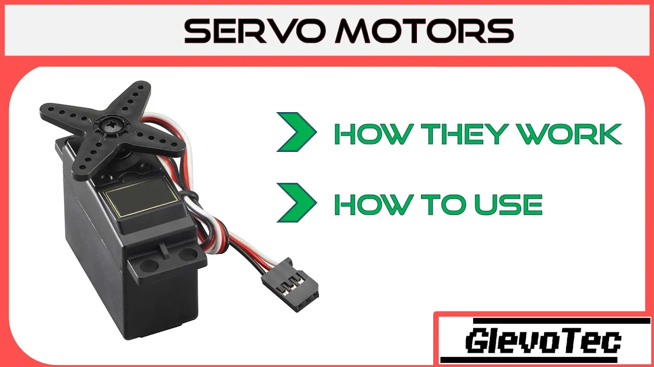
An understanding of how servo motors operate and receive angular positioning commands.
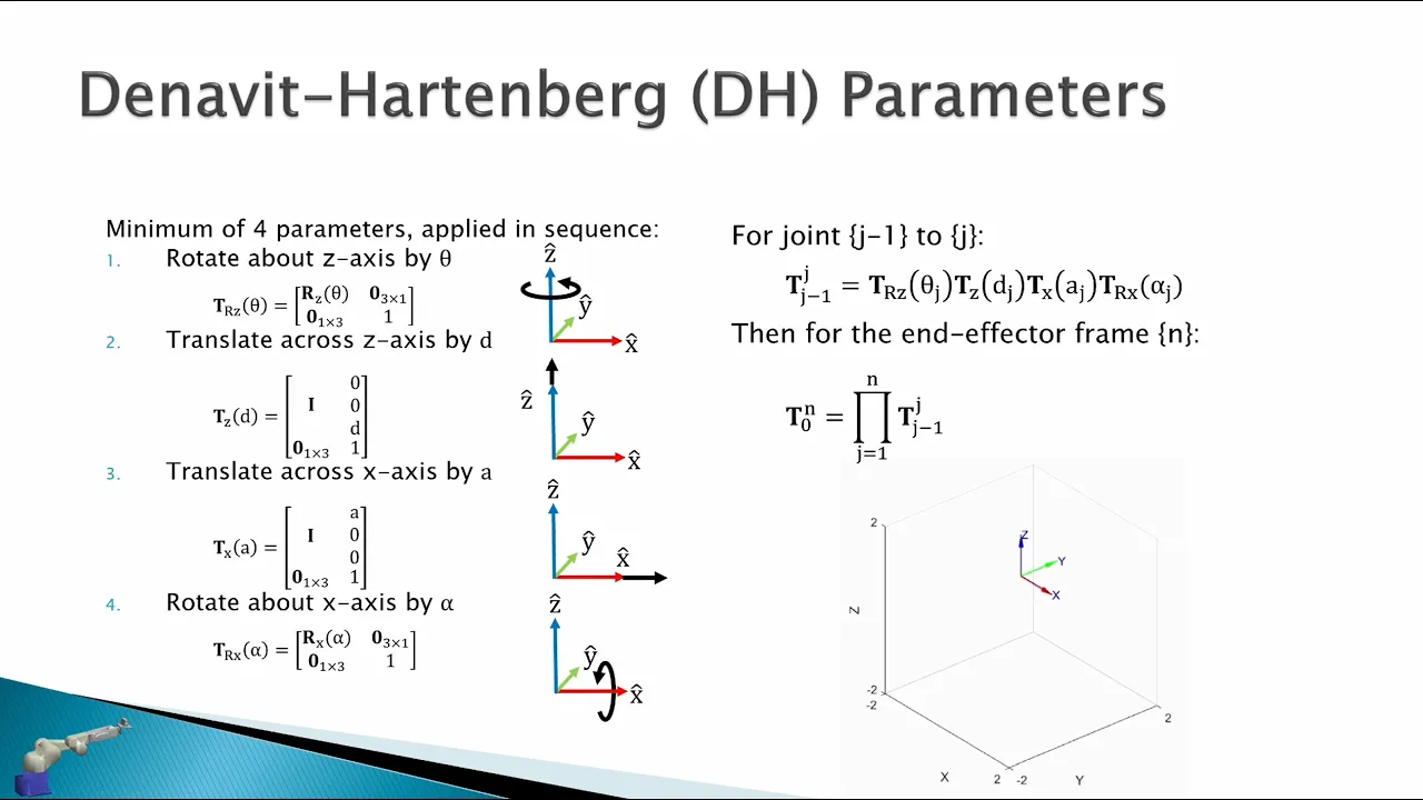
Systematic robot modeling using Denavit-Hartenberg (D-H) parameters for multi-joint configurations.
Numerical Inverse Kinematics methods, such as using the Jacobian matrix for arms with higher degrees of freedom (DOF).
Trajectory planning and motion profiling to ensure smooth path-following (e.g., linear or arc-based movements).
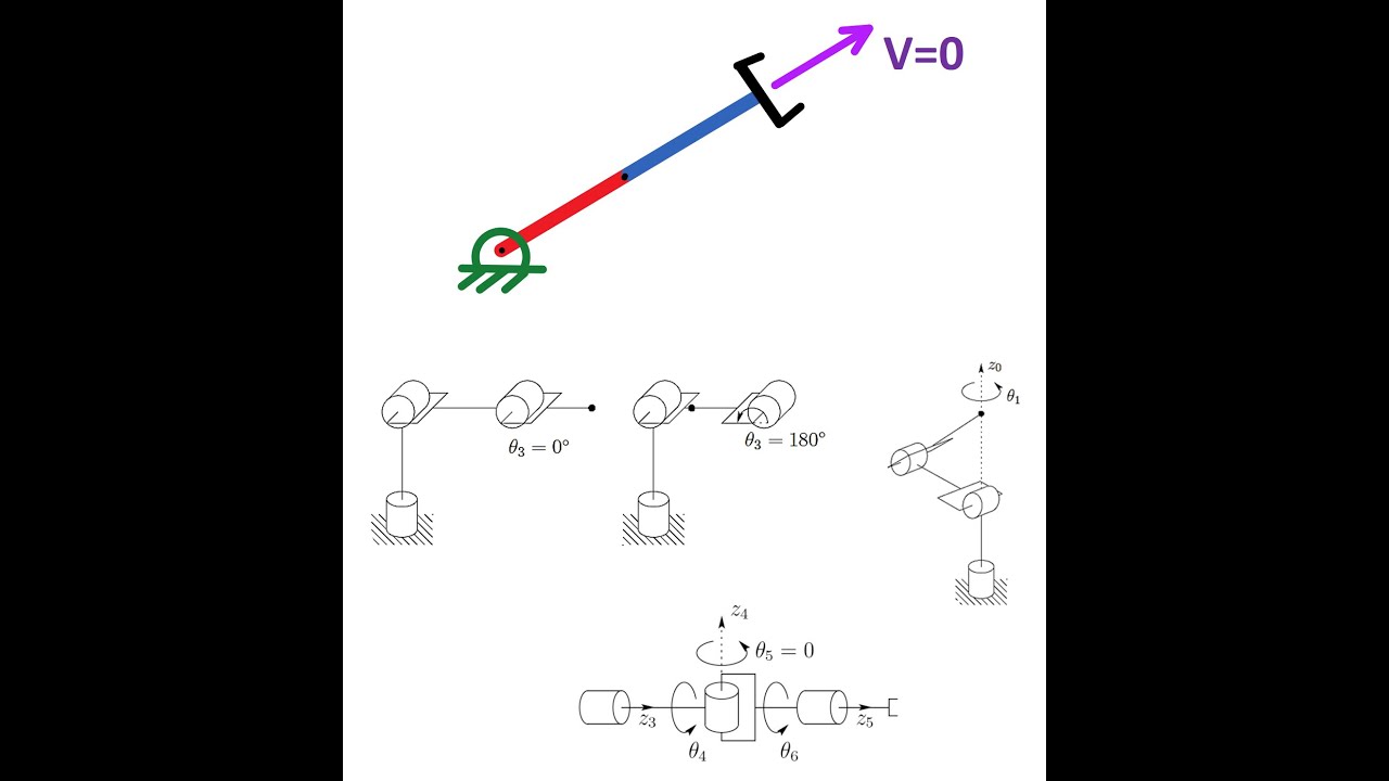
Identifying and managing kinematic singularities where mathematical IK solutions become undefined or unstable.
Integrating kinematics algorithms with higher-level robotics middleware like ROS (Robot Operating System) and motion planning libraries like MoveIt.
135.5K views5.1Klikes5:48Original Release: 2022-01-23
it's easy to assume that just because inverse kinematics uses maths it's difficult it's really not in this video i'm going to show you how to use five simple lines of maths to calculate the inverse kinematics for this little robot arm we'll be using the robot arm i built in the last video in this series well almost the same one i've upgraded it since then with these new servos and these ball bearings just to give it a smooth emotion let's say we have a point here at x equals 10 and y equals 5. we can then raise it up in the air slightly so let's say that z equals 5 here as well this is the point that we want to move our robot to the first axis we want to consider on our robot is the rotation of the base now this doesn't affect the height of the gripper at all so nothing in the z direction this means that we can find out the angle of the base simply by drawing a line from zero zero to our point in x and y the angle here will tell us the angle that we need to move the robot's base to let's label that v we can use very simple trigonometry to work out this angle we simply say that tan of the angle b is equal to the opposite over the adjacent which is 5 over 10 in this case we also need to work out the length of this side let's call it l using pythagoras we can say that the square of l is simply the square of this side plus the square of this side now that we've worked out the angle for the base we need to start considering the other arms we can define a new plane here with z as one axis and the side l that we just worked out as the other axis here's the new plane taken onto a fresh piece of paper and here's our point that we want to move the robot arm to in relation to both the z axis and our new l axis to keep things simple to start with we're going to pretend that we've got a single arm here instead of two arms now in order to move our arm to the right point we're going to need to know two things we're going to first of all need to know what angle that we need to move here and we're going to need to know the length of this arm we'll call them phi and h so using the same maths as before we know that tan of this angle here phi will equal the opposite over the adjacent which is z over l and we know that the square of h will equal the square of z plus the square of l now if we draw our two arms on here we can see that we can make this one arm defined by an angle and a length up by two arms just defined by two angles the next thing to do is to find this angle here which we'll call theta in this case this is nice and easy because on our little arm both of these arms are the same length in this case 75 millimeters so we can simply split this isosceles triangle defined by these three lines into two right angle triangles now we know the length of two of these sides 75 and h over two we can say that the cosine of theta is equal to the adjacent over the hypotenuse which is h divided by two over seventy-five thankfully that's all of the trigonometry done now we just need to work out how to transform our angles phi and theta into the actual angles that we want our arm to move to i find this a lot easier to visualize if i mirror our two arms here down here so that we create a parallelogram we know that the angles this end and this end must match as much the angles here and here this means the two angles we need to find are this one for the first arm which we'll call a1 and then this one here for the second arm it's difficult to see up here exactly what it relates to so we're going to move down to the bottom here we know that this angle is exactly the same as what we were just looking at so we'll label that a2 now we had our angles from before phi and theta and it's easy to see that our angle a1 for our first time is simply equal to phi plus theta and our angle a2 is equal to phi minus theta and that's it that's all the maths we need to do to know how to position our arm let's have a look at the code so this small function is all we need to be able to perform the inverse kinematics we simply take in our x y and z coordinates and then do all the trig and pythagoras theorem that we were just going over translate them into the a1 and a2 angles that we just worked out and then tell our arm to move to those angles if you want to see the rest of the code for this project please check out my previous video on the subject which i'll link up in the corner now at last we can see our little robot r move in straight lines in both the x and y directions and then also in the z and l directions any small inconsistencies are down to the cheap little servos that we're using for the arm here if i've helped you understand this or made you think about it in a different way please hit the like button to let me know consider subscribing for more projects like this and let me know down in the comments if there's anything else you'd like to see if you would like to build your own arm or just check out the code for this all of the cad encoder as always on my github page which is linked down below
Up Next
20:38
Camera to World Coordinate Mapping | Robotics Vision Tutorial
@asodemann3
6.4K views•2017-10-04

75:08
RatSLAM: Biologically Inspired Robot Mapping and Navigation
@milfordrobotics
20.9K views•2012-08-03

11:04
How to Build a Self-Balancing Robot: Arduino Nano & MPU6050
@easytechzones
16.8K views•2022-03-09

58:11
Introduction to Robotics | Stanford CS223A Lecture 1
@stanford
744.4K views•2008-07-22
Related Study Plans & Knowledge Roadmaps
Structured learning paths in Robotics
robotics
CDPR: Kinematics, Arduino & Winch Control
01Foundations of Arduino & Basic Electronics
02Stepper Motors and Winch Mechanics
03Kinematics of 2D Cable-Driven Robots
+ 2 more learning modules
28h5 modules
Explore Roadmap
robotics
Rocker-Bogie Rover: Build, Stereo Vision & ROS
01Physics and Kinematics of Rocker-Bogie Suspension
02CAD Design, 3D Printing, and Assembly
03Actuators, Power, and Microcontroller Integration
+ 3 more learning modules
48h6 modules
Explore Roadmap
robotics
Building AGVs: QR Navigation & Lifter Systems
01Introduction to AGVs & Embedded Electronics
02Chassis Design & Lifter Mechanics
03Computer Vision & QR Code Localization
+ 2 more learning modules
32h5 modules
Explore Roadmap
robotics
EMG Exoskeletons: Design, Control & Actuation
01Electronics & Microcontroller Foundations
02Biomechanics & EMG Sensor Fundamentals
03Actuators & High-Torque Mechanisms
+ 3 more learning modules
50h6 modules
Explore Roadmap