

![[Sistemas Lineares] Posto e Nulidade](https://i.ytimg.com/vi/yWTAHeS3MoE/sddefault.jpg)
![3D Programming Fundamentals [3D Perspective Projection] Tutorial 4](https://i.ytimg.com/vi_webp/UgM6mIQfGDA/maxresdefault.webp)


![[Introduction to Computer Vision] 4. Camera Calibration](https://i.ytimg.com/vi_webp/rHYFqx87wvE/maxresdefault.webp)



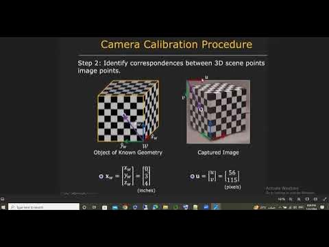




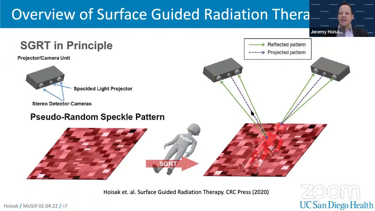








When a camera is tilted relative to a planar surface, pixel-to-world coordinate conversion varies across the image, requiring an empirical mapping approach where known reference points are used to create separate polynomial mappings for Y-position and pixel-to-centimeter conversion in X-direction, enabling accurate transformation between camera pixel coordinates and world coordinates; this structured light approach is widely used in robotics applications like the Microsoft Kinect sensor.
Camera to World Coordinate Mapping | Robotics Vision Tutorial
Added:Fundamental Linear Algebra: Understanding matrix transformations, rotation, translation, and homogeneous coordinates.
The Pinhole Camera Model: Familiarity with intrinsic and extrinsic camera parameters and how 3D points project onto a 2D image plane.
Basic Camera Calibration Techniques: Awareness of standard calibration methods (like Zhang's method using checkerboards) to determine camera parameters.
Trigonometric Triangulation: The mathematical principles of calculating the distance to a point using angles and baselines.
Advanced Structured Light Patterns: Exploring coded structured light techniques (such as Gray codes and sinusoidal phase-shifting) for dense 3D reconstruction.
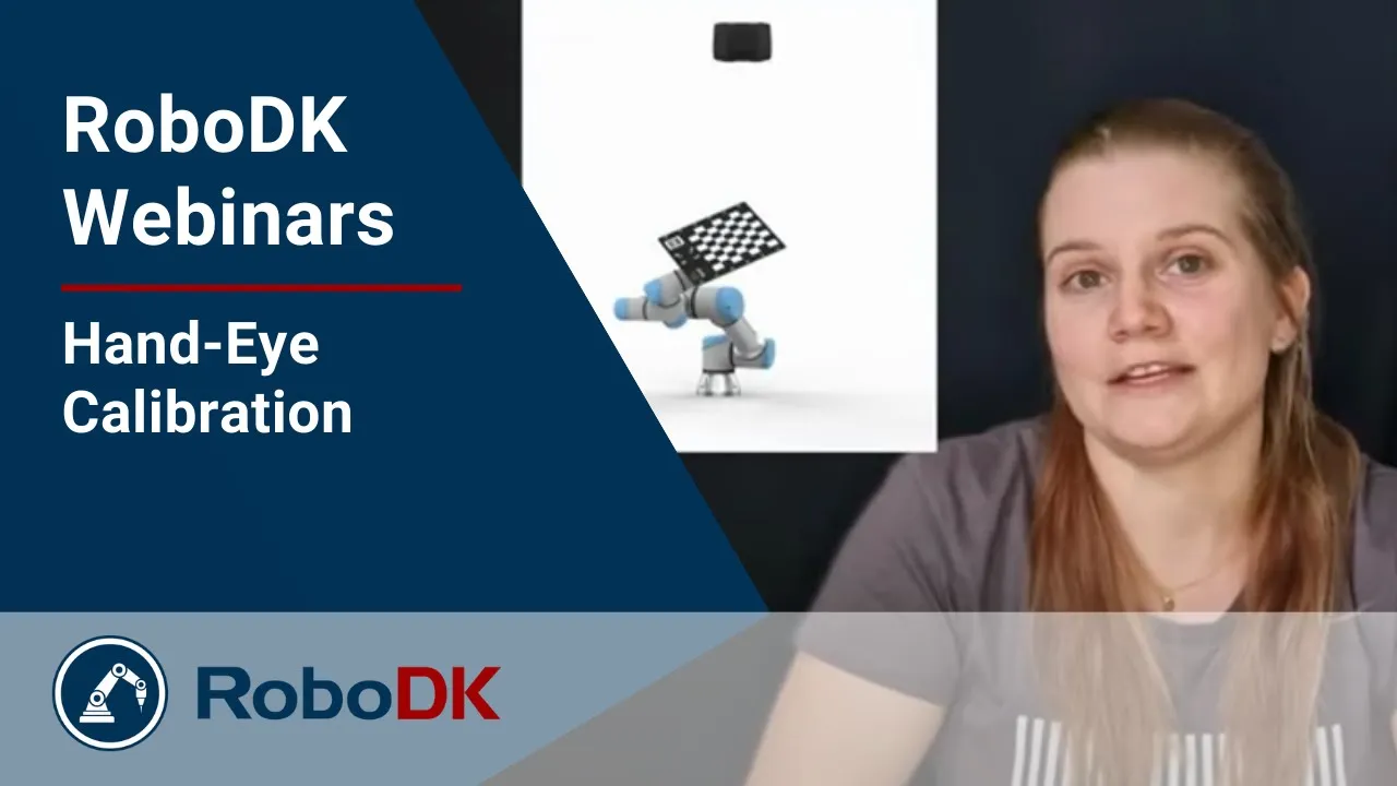
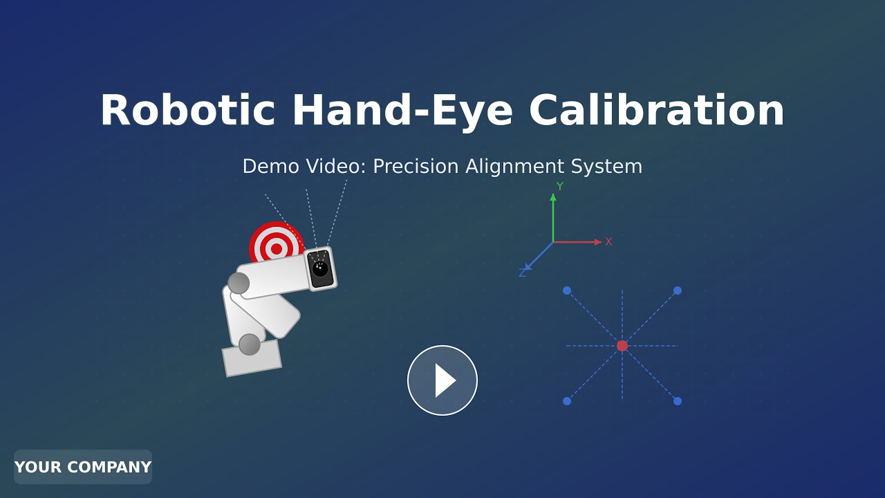
Hand-Eye Calibration for Robotics: Learning how to map the camera's coordinate frame directly to a robotic manipulator's base frame for precise physical interaction.
3D Point Cloud Processing: Utilizing libraries like PCL or Open3D to filter, segment, and register the reconstructed 3D spatial data.
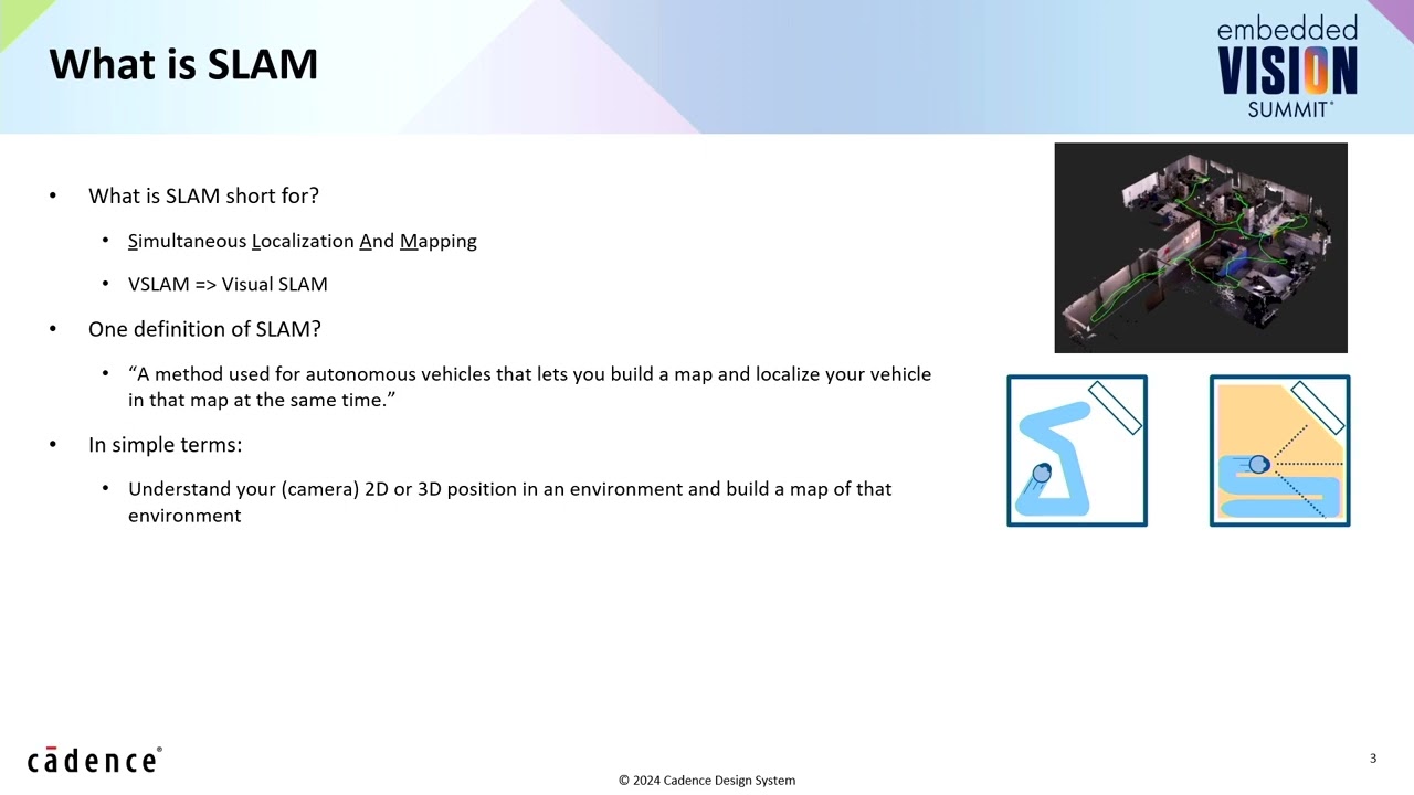
Visual SLAM (Simultaneous Localization and Mapping): Applying spatial mapping concepts to track a moving robot's position while mapping its environment.
6.4K views95likes20:38Original Release: 2017-10-04
in the last video we learned about Canberra transformations in the case where we can assume that the camera sensor is parallel to the plane that the camera is looking at but in many practical situations this is not true I'm showing here an image that I captured by placing my camera at an angle looking at my board in this picture this is the x0 y0 position on the board and what we're looking at is a bunch of squares that are each 1 centimeter by 1 centimeter just like you have printed on your board this kind of a case is more difficult than the other case we looked at in the last video because as you'll notice in this picture the pixel 2 centimeter conversion factor is different in different places on this board and also the pixel 2 centimeter conversion is not the same in the X direction as in the Y direction in other words these are actually squares but in this perspective they look like rectangles now if we know the angle of the board relative to the direction of view of the camera and we also know the field of view of the camera we could figure out the camera transformation analytically but this is often not a practical solution because in practice we often don't know for sure what is the angle of the plane that we're looking at relative to the direction of view of the camera in this kind of a case we can solve this problem using an empirical approach in which we create a mapping of the points that we see to the world coordinates that's the solution that I'm going to show you how to do today and we're going to do this using this specific example so what we are going to solve today we're going to find some equations that will allow us to take as input the pixel location of an object as identified by the camera and it will output the XY position of that object in units of centimeters in what we call world coordinates that is in the coordinate frame that is attached to the board in the world now in the mapping process that we do in this video I'm going to assume that the world is rotated around its own x axis here but it is not rotated around its Y axis or in other words the camera is not tilted left and right the camera is just tilted up and down so to begin solving this problem notice first of all that the pixel two centimeter conversion is maximum down here in the bottom of the screen and it decreases as we get higher in the screen this is true both for the vertical Direction pixel the centimeter conversion as well as the horizontal pixel the centimeter conversion although the value of the pixel the centimeter conversion is different in the up-and-down Y direction than it is in the left-to-right X direction here's the order that we're going to use to solve this problem I'm first going to create a mapping in the Y direction to figure out the Y position of the object in the base frame or in the world frame once we've figured out the Y position of the object in the world frame I will use that Y position as input to figure out what is the pixel two centimeter conversion in the X direction and then use that to find the x position so I've opened this picture in paint and you'll notice that with my pencil tool I can point to different places on the screen and in the lower left-hand corner down here it will tell me which pixel in the x direction and which pixel in the y direction I'm pointing it I've also opened up Excel because this is what I'm going to use to record the data that we'll use to create this mapping the first thing I want to do is find a mapping between the Y pixel location and the Y world location I'll create a place in Excel to hold this information so I'll merge these two cells together and say that this is our world coordinates and I'll call this the X position and this the Y position and then these are our camera coordinates x and y keep in mind that our world coordinates have units of centimeters whereas our camera coordinates here have units of pixels for this first part of the mapping I only care about the Y position so I want to capture some data where the x position is all zeros and we'll get a couple of the Y positions maybe 0 2 4 6 and 8 so I'll position my pencil right at 0 0 and I see that the pixel location of 0 0 is 321 468 now I'll put my little pencil at 0 2 319 342 and then at 0 4 3 21 251 these numbers aren't exact but that's okay because we'll be fitting this line so it doesn't have to be exact 0 to 4 here's 0 6 3 21 185 and then 8 0 2 4 6 8 3 24 1 32 ok now we want to plot this data we want to be able to take as input some Y pixel value and produce as output a Y value in the world coordinates so I want these numbers to be on the x axis of my plot and I want these numbers to be on the y axis of my plot then I do insert I want a scatter plot like that and it swapped around the axes how I want them now I'll right-click on the data and click on select data and then remove this series and then add a new series and select the X values I want these to be the X values because that is going to be my input and the Y values here so here's the chart that I get out I'm going to label these axes right away so we don't forget what we just plotted here okay let's give a label to these axes so that we don't forget what we plotted here click on the chart and then there's this little plus sign here let me slide this over so you can see what's happening I click on the plus sign and then I want to check axis titles like that then I'll have the titles show up here and I can double click and then type in what I want here this is the camera Y in units of pixels this is the world coordinates Y value in units of centimeters now click on the data and then right-click on it and then select add trendline by default it starts by giving you a linear trendline but that actually doesn't fit our data very well one way you can tell that is if we scroll down and we click display equation on chart and then we click display r-squared value let me drag this up here the r-squared value is only about 0.97 I would like to have at least 0.99 for my r-squared value for a really good fit so let's go back to the trendline and instead of linear let's do a polynomial fit of second-order and here we get an r-squared two point nine nine nine so this is pretty good I'm gonna go with that now that we have this equation we can use it to calculate the Y position in centimeters given the Y position in pixels of an unknown position so let's create a place to do that in our spreadsheet now in our output cell I'll hit equals and I'm going to type in this equation right here X is the Y position in pixels let's test our equation suppose that we detect an object located right here the Y pixel value here is about 132 and the Y position in world coordinates is zero one two three four five six seven eight so we'll type in 132 and hit enter and it tells us that our Y position is seven point nine so that's pretty close to being correct now let's see if we can get the x position also in order to get the x position I need to keep track of what is the pixel two centimeter conversion in the X direction at different values of Y now let's start at the Y value of zero I'm going to look at the x pixel value it's 320 then I'll go look at the x pixel value over here which is 489 since that distance is one centimeter if I take the difference between these two numbers of pixels this is the pixel two centimeter conversion in the X direction at the Y position zero now let's do it at two the center is still 320 and over here it's 464 let's do the same thing at 4-4 43 and it's 6 429 and then at 8 0 2 4 6 8 for 19 here I want to take as input the Y position of the object and produce as the output the pixel 2 centimeter conversion in the X direction so I'll select the Y value and the pixel 2 centimeter values and we'll insert a scatter plot let's add axis titles then click on the data right-click add trendline I'll scroll down to the bottom and check display equation on chart and display r-squared value now to use this value in our calculation we need to do an intermediate calculation of the pixel two centimeter value remember that in our pixel two centimeter conversion the input X is the Y position in centimeters once we know the pixel two centimeter conversion at this particular y value we can use that to calculate the x position since the zero x position is right in the center at pixel 320 to get the x position in centimeters we take the x position in pixels subtract 320 and then divide by the pixel per centimeter value let's test this equation suppose we detected an object right here this is x equals two and y equals six the x pixel position is 536 and y is 182 and here it says that our position in world coordinates is two and X and six in Y so the calculation is pretty accurate now before we conclude today let me make a couple of notes about the usefulness of this approach to converting between camera coordinates and world coordinates in practice in this example we have a grid that was printed on a board that is positioned at an angle relative to the camera but let's suppose that we were using this out in the world with a robot moving around a general unstructured environment that environment probably doesn't have a grid already printed on it however suppose we gave our robot the ability to project a grid in front of it the grid projected by the would also be distorted not in the same way that this printed grid is distorted but the distortion would be similar we could then have the robot look at its own grid and automatically extract the data points that we extracted by hand in this video and in that way the robot could find its own conversion between camera coordinates and world coordinates and in that way deduce the positions of objects around it in the world coordinates this approach is known as a structured light approach and it's the approach used by the Microsoft Kinect sensor and many other robotics applications that are out there in industry right now
Up Next
3:04
Robotic Hand-Eye Calibration: Precision Alignment Demo
@iandai-1
315 views•2025-04-27

58:25
MathWorks Virtual RoboSub Simulation Environment | Webinar 2026
@RoboNationInc
209 views•2026-03-10

17:01
Rotation Matrices in Python | Robotics Kinematics Computation
@asodemann3
58.6K views•2017-06-11

25:22
Micromouse: The Fastest Maze-Solving Robots on Earth
@veritasium
23.5M views•2023-05-24
Related Study Plans & Knowledge Roadmaps
Structured learning paths in Robotics
robotics
Building Delta Robots: Kinematics & Pico
01Foundations of Delta Robots & Mechanical Design
02Electronics and Microcontroller Setup with Pi Pico
03Delta Robot Kinematics and Coordinate Math
+ 3 more learning modules
65h6 modules
Explore Roadmap
robotics
Building Ballbots: Dynamics, Kalman & LQR
01Embedded Electronics & Omniwheel Actuation
02Ballbot Kinematics & Rigid Body Dynamics
03IMU Sensors & Kalman Filter State Estimation
+ 2 more learning modules
42h5 modules
Explore Roadmap
robotics
Micromouse: Hardware, PID Control & Flood-Fill
01Electronics & Teensy Microcontroller Basics
02Sensors and Actuators: Motors, Encoders & IR
03Precision Movement: Implementing PID Control
+ 2 more learning modules
35h5 modules
Explore Roadmap
robotics
CDPR: Kinematics, Arduino & Winch Control
01Foundations of Arduino & Basic Electronics
02Stepper Motors and Winch Mechanics
03Kinematics of 2D Cable-Driven Robots
+ 2 more learning modules
28h5 modules
Explore Roadmap