









A functional filament recycling system for 3D printing requires integrating multiple interconnected components including cooling fans, measurement sensors (such as photoresistors or digital calipers), tension control mechanisms (polar and reeler), and a coordinated control system with PID controllers; successful implementation demands careful attention to mechanical design, electronic integration, and iterative troubleshooting to overcome challenges like inconsistent measurements, mechanical jams, and electrical issues.
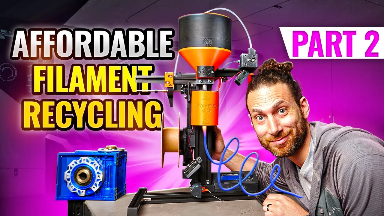
Optimizing Filament Recycler Downstream Stages: Part 2
Added:Fundamentals of thermoplastic extrusion, including melt flow behavior and thermal properties (melting points and glass transition temperatures) of common polymers like PLA and PETG.
Basic knowledge of upstream extrusion mechanics, specifically how plastic pellets or shredded waste are fed, melted, and pushed through a nozzle.
The physical relationship between mass flow rate, pulling speed, and final filament diameter (conservation of mass principles in extrusion).
Familiarity with basic electronics, stepper/DC motor speed control, and how optical or physical sensors measure dimensions.
Implementing automated closed-loop feedback systems (such as PID control loops) to dynamically adjust pulling speed based on real-time diameter measurements.
Material testing and quality assurance procedures to evaluate the mechanical properties, moisture levels, and printability of the recycled filament.
Advanced compounding and polymer blending, including the introduction of virgin plastics, colorants, or reinforcing additives to restore degraded physical properties of recycled materials.
Life cycle analysis (LCA) and industrial scale-up strategies for transforming desktop-scale DIY recycling setups into high-throughput circular economy systems.
9.6K views281likes17:53Original Release: 2024-11-17
we did it we successfully turned plastic fragments into strands pulling the strands with pliers however will never get us the consistent filament we need as I mentioned in the last video this curly strand of inconsistency can be cooled measured pulled and spooled to hopefully get usable filment this video explores the creation of each of those Downstream stages and throughout I will try my best to explain how each should work the sketch was a good start but CAD will allow me to start bringing these ideas to life the first and easiest piece would be fans to cool the filament as it stretches for that I need a fan Mount designed in such a way to maintain structure while allowing air flow I was able to acquire a three pack of computer fans that should do just the trick once I figure out which wires provide Power one fan will cool the drive motor and the other two will cool the filament as it extrudes the next stages I wanted to tackle were filament measurement and spooling this introduced the first hurdle I had to overcome stepper Motors my flying RC car project and prior participation in robotics provided me with experience in brushless and brushed motors but I had never designed something that needed steppers before through the magic of editing all of this becomes a working motor and flies us through all the research and experimentation for filment measurement let's take apart a set of calipers digital calipers work by reading the movement of a printed circuit board as it is pulled along with the opening and closing of the draws the board converts that movement into digital signals which are output to a display traditionally digital calipers have a battery and are entirely self-contained there are however four pads which can provide Power and output the digital signal from and to an outside Source respectively in my case the green and yellow wires provide the signal and the red and black wires provide Power the resistors capacitor and led in the power chain regulate the input power and ensure the calipers get what they need this assembled frame offers two parallel rails for the jaws of the caliper to open and close upon a few 3D printed parts are needed to mount the Jaws to the rails those parts and some bearings should create a mechanism that sandwiches the filament between two roller bearings the diameter of the filament should cause the Jaws to separate to the measurement of said diameter after loading in the calipers and writing up some code to read the digital signals I can test this concept unfortunately in reality the friction in these calipers and the system as a whole cause a lack of sensitivity and inaccurate results this might work with a bit more tweaking and some lubricant or smoother calipers but my confidence in it is low instead I want to try something different I want to try using light this device is called a photo resistor it provides a signal based on how much light is it exposed to coupling it with an LED I can create a constant light exposure when the filament passes between the LED and the photo resistor it'll block some of the light from the led the blocked light will cause the photo resistor to Output a lower signal as the filament passes through any changes in diameter will result in a larger or smaller Shadow thus blocking more or less light and creating a change in Signal the computer can use to determine the deviation from the nominal diameter and hopefully adjust accordingly as you can see here with everything wired up the LED affects the photo resistor as I previously described moving it closer to the photo resistor increases the value read by the computer and moving it further away decreases it by holding both of these at a constant distance and pushing filament through you can see the effects of the shadow on the photo resistor despite this being consumer filament there is still Shadow variation due to the relative proximity to the LED being closer produces a larger Shadow than being further away the hope is the tension in the filament will hold it centered printing an enclosure box and assembling these components into it fixes the two elements at the needed constant distance and provides a shroud from external lights to help ensure constant nominal readings feeding filment through the box and performing a rolling average gives a promising result that again with machine Precision will hopefully work the last two stages are a polar and a reeler the polar squeezes the filament between two wheels and rotates them to control the tension from the molent pool generated by the extruder that print partially failed which if this work works it isn't a big deal as I can just recycle it the reeler uses a large acne thread to slowly move a bar with a guiding hole back and forth to allow us to regulate the filament into a tight spool as the spooler rotates with all these components the code gets quite complicated hours of conversation with these really smart rocks Humanity tricked into thinking paired with a proficient understanding of programming yielded two scripts the first is a python script that generates a graphical user interface allowing me to click buttons that send serial Communications to the second in our guo program which receives those signals and triggers the movements of the stepper Motors the GUI has dedicated buttons for each stage with direction and speed controls and also outputs the light values Red by the Box logic is also in place to scale the speeds of each stepper by the changes in the light values once the PID controller is turned on the code does nothing without wiring the components so poof cabling rats nness with everything wired up I can run my first test which I'm sure will go off without a hitch and won't make awful noises and require hours of troubleshooting and we'll go perfectly [Music] so nothing really works at all especially the reeler it likes to make banging sounds and doesn't even work when I methodically smack it even with some lubrication the reeler and also the polar would rather click than rotate swapping the pla rollers on the Polar for TPU should help it get a grip on the filament reducing the engagement area of the reeler slider should decrease its chance of getting caught and make it operate more smoothly those upgrades seem to have worked and polar seems to be quite smooth now laying this out on my only fire resistant surface really provides perspective on just how massive and involved this is there are so many potential points of failure that I might be getting over my head with the complexity of this project well there's no time like the present let's boot this sucker up [Music] so okay [Music] well we got close the best result was a about a 3T strand of roughly 1.3 mm filament the diameter stays mostly constant clogs and jams however in the extruder cause periods of material drought and then periods of material Surplus which makes these awful looking ones let's start tackling the shortcomings this motor driver is useful in that it allows for the manual adjustment of speed and direction however it is completely decoupled from the rest of the system it also doesn't have any feedback on power to fix that I'm going to try to replace it with moss V Moss beds are electrical switches that allow for large current control small current signals these Moss beds however are garbage they do not work they are bad while I wait for better ones to arrive I'll redesign and reprint a few pieces from the spooler to the light box to the cooling system the light box has been upgraded from an LED to a laser lasers have much straighter beams which should mitigate the proximity to the light source issue additional insulation will help serve two purposes one it will help to maintain heat allowing for the system to heat up faster and two it will allow me to Mount and thermally isolate a plastic feed funnel on top the extruder which will help me guide material into the chamber the spooler spool holder gains some structural integrity and a little nub to help Drive the rotation of the spool without slippage the those side quests passed enough time that the better moset arrived this is specifically designed for what I'm trying to do so somehow giving it 6 amps was just enough to make the motor turn but that ground wire which doesn't seem like it would want to carry 6 amps came all the way over here and did that how peculiar huh this voltmeter sensor thing was the culprit the positive and negative terminals were connected to this negative terminal which came to my Common Ground so even after adding a USB isolator it was still creating some sort of ground Loop or something so taking this out makes it so that it works now and I'm not 100% certain that I even need the voltage sensing so we should be all right so we burned out the old one of these we bought a new one of those and fixed that turns out we do actually need voltage movement because with just current measurement when I turn it on it does run at a constant speed and I'm giving it half of the PDM pwm value and the way have it coded is that when you add more friction the amperage goes up on both the pwm signal goes up problem is when I Let Go it has no way of knowing that it's now going way faster than it needs to even though the current has reset to where it was so I need the voltage to tell how fast it's spinning which means I need to take the wires that I already just cut off and I need to resolder them on here and then put them into this which of course I burned when I soldered so hopefully that still works this wiring at least sort of works I did have to get a ground jumper a ground jumper from the minus back to the source so that it doesn't fry itself uh I also had to set it so that pin nine the first and 10 that's the [Music] second and that allows me to get motion and both which is what I want without anything catching on fire SL burning SL moldering which just kid I clearly need to do that better that better but Pro Concepts there for [Music] [Music] [Music] of course after all that I wired it backwards so it spins in the wrong direction after a careful swaper we have rotation in the correct direction somehow in just moving the motor across the room stopped working giving it power results in no motion it looks like the power source is Railing at maximum current which means I fried something I bought replacements for everything and a dedicated power supply for this motor and after replacing the fan team off f it seems to be working again now we have the everything code going and when I flip the switch hopefully the motor turns on that's on that's on all that's on fans are on nothing appears to be on fire Victory now we just have a whole lot of programming to do the program works great the polar button makes the polar start the spooler button makes the spooler start and the reeler button exposes that I didn't fix the reeler the first time luckily I can fix that by just using a better 3D printer seriously bamboo Labs knows what they're doing this thing is crazy can you just swap out the old one real quick now let's see if these upgrades did anything [Music] well there's clearly more work to do the P controls of the motor still need tuning the laser light system still needs testing the reeler and spooler have to get material to them so they can be used the program needs to stop losing connection and crashing and I really need to clean up how this thing looks if you have any ideas for fixes for any of those things please leave them in the comments sorry that I couldn't get it working quite yet this video is already long and I have no idea how long it's going to take to get it fully functional if you want to see where this goes please subscribe so you get notified see you sorry it took me so long to post a video I've had a lot going on I moved I got a cat and between my job and vacation I was out of state over 100 days this year which makes it hard to work on projects at home hopefully my schedule is now more conducive to being able to work on these projects see you in the next one
Up Next

6:10
How Cavitation Damages Battleship Propellers
@BattleshipNewJersey
75.4K views•2024-03-19

30:32
Ultrasonic Transducers: Resonant Frequency Measurement and Horn Design
@imajeenyus42
229.9K views•2017-02-22

54:16
Polymer Environmental Degradation: Mechanisms & Stabilization
@iit
1.8K views•2012-07-10

33:39
How a Student's Question Saved a NYC Skyscraper from Collapse
@veritasium
22.8M views•2025-04-26
Related Study Plans & Knowledge Roadmaps
Structured learning paths in Engineering
engineering
Building Acoustic Levitators: Physics & Arduino
01The Physics of Sound and Standing Waves
02Piezoelectric Transducers and H-Bridge Drivers
03Arduino Programming: Generating 40 kHz Signals
+ 2 more learning modules
14h5 modules
Explore Roadmap
engineering
Building Peltier Cloud Chambers: Particle Tracks
01Cosmic Rays & Cloud Chamber Physics
02Thermoelectric Cooling (TEC) Fundamentals
03Custom Liquid-Cooling Loop Design
+ 2 more learning modules
18h5 modules
Explore Roadmap
engineering
Yagi-Uda Antennas: Modeling, Build & VNA Test
01Introduction to RF and Antenna Fundamentals
02Yagi-Uda Antenna Design Principles
03Antenna Modeling and Simulation in 4NEC2
+ 2 more learning modules
18h5 modules
Explore Roadmap
engineering
ECG Monitor Design: Op-Amps, Filters & Noise
01Electronics & Breadboard Basics
02Op-Amps and Instrumentation Amplifiers
03Bioelectricity and ECG Fundamentals
+ 2 more learning modules
18h5 modules
Explore Roadmap