
















![ZIEGLER NICHOLS ✅ SEGUNDO Método [Control PID] Parte 2](https://i.ytimg.com/vi_webp/AAaWNNuqpuY/maxresdefault.webp)














A linear servo actuator is a closed-loop control system that converts rotational motion from a DC motor into precise linear motion using a lead screw mechanism, where a magnetic rotary position sensor (AS5600) provides feedback to a PID controller that adjusts motor speed to achieve accurate positioning; this system can be controlled via analog inputs (potentiometers), digital inputs (RC receivers), or serial communication from a computer, allowing users to set custom start/end positions, adjust sensitivity, and program repeatable movement sequences.
Build a DIY Linear Servo Actuator with Position Feedback: A Step-by-Step Guide
Added:Understanding the working principles of DC motors and how motor drivers (e.g., H-bridges) control speed and direction.
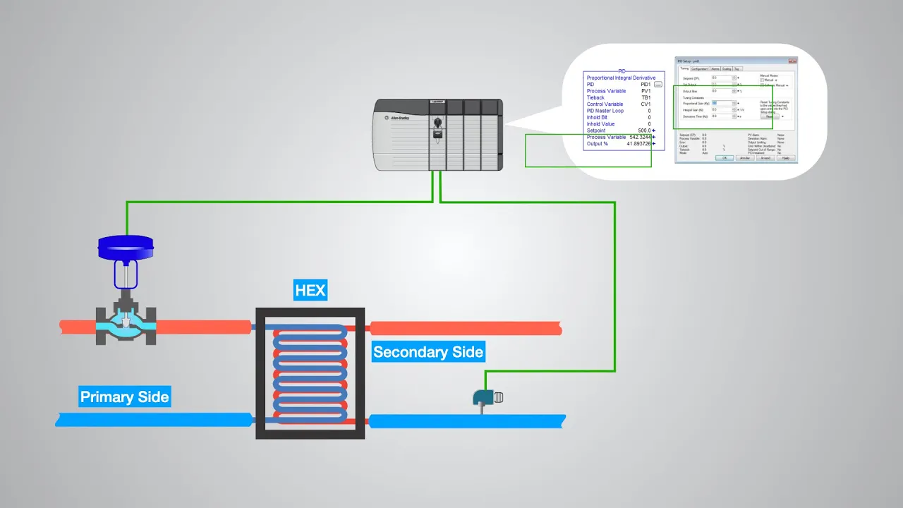
Basic knowledge of closed-loop control systems, specifically the theoretical concepts of Proportional-Integral-Derivative (PID) controllers.
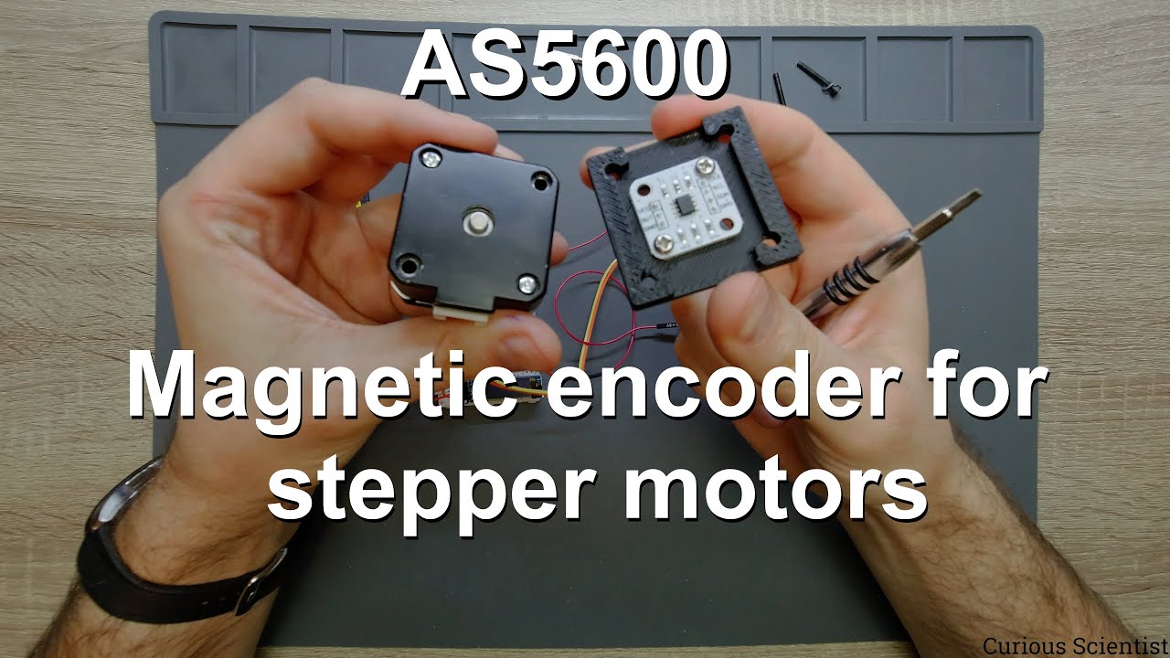
Familiarity with magnetic rotary encoders (like the AS5600) and how they measure angular position using protocols like I2C.
Fundamental microcontroller programming (e.g., Arduino/C++) and interfacing with sensors and actuators.
Basic mechanical concepts of converting rotary motion to linear motion (e.g., using lead screws or threaded rods).
Advanced PID tuning methodologies (such as the Ziegler-Nichols method) and auto-tuning algorithms.
Transitioning from brushed DC motors to brushless DC (BLDC) motors using Field-Oriented Control (FOC) for improved efficiency.
Integrating linear actuators into complex multi-axis robotic systems, such as robotic arms, CNC machines, or animatronics.
Implementing safety and diagnostic features, including overcurrent protection, homing routines, and limit switch integration.
Exploring industrial communication protocols (e.g., CAN bus or Modbus) and ROS (Robot Operating System) for distributed actuator control.
254.4K views4.4Klikes23:58Original Release: 2024-01-18
hello down here from how mechatronics tocom and in this video we will learn how to make a linear Servo actuator unlike regular linear actuators that move in a particular direction when a voltage is applied this custombuilt linear Servo actuator provides precise and repeatable movements that can be easily controlled it's called a Sero actuator because it features a feedback loop system through which we can control the actuator output motion accurately the input for controlling this linear Servo actuator can be either analog or digital in the case of an analog input it can be any type of potentiometer like shown here a linear potentiometer or a common rotary potentiometer or for example a joystick which is again a rotary potentiometer and so on in case of a digital input we can control the actuator with an RC transmitter of course for this setup we also need an RC receiver which goes as an input to the actuator for both these analog and digital input modes we only need three wires to make a connection two of which are for powering the input device and the third one is for the input signal a cool feature this custombuilt linear Servo actuator has is that we can set a custom start and end position for the output Rod as well as adjust the sensitivity or how quickly the actuator will respond to our input though my favorite feature is the ability to control this actuator from a PC or laptop through a Serial por communication we can enter values in millimet through the Arduino ID serial Monitor and the actuator will move to that position what's even cooler we can make a repeatable movements or store the positions by typing safe on the serial monitor at each position we want and then tell the actuator to repeat the movements in a loop by typing run on the serial monitor now let me explain everything you need to know about this custom build linear Servo actuator how it works and how I designed it so you can also build one on your own so the close loop control system is based on the as5600 magnetic rotary position sensor and the implemented PID control for driving the DC motor actually I'm using the same custom Servo motor controller board that I made in my previous video which includes its own microcontroller and everything else to easily turn any DC motor into a standalone Servo motor you can check that video out for a detailed explanation of how a Servo motor and a Clos Loop control system works real quick a Servo motor is a Clos Loop control system where the input signal or the desired position is compared to the actual position of the motor that we get from the position feedback sensor the difference that occurs which is called the error is then processed in the controller which commands the motor to move until it reaches that desired position so this linear Servo actuator has the same working Principle as a servo motor but with one additional step of converting the rotational motion of the motor into a linear motion with the help of a lead screw mechanism here's the 3D model of this linear Servo actuator from where we can see how everything works the as5600 magnetic rotary position s is located at the back side of the actuator and it keeps track of the rotation of the lead screw the lead screw that I use has 8 mm speech which means with each full rotation the lead screw nut makes 8 mm linear motion the as5600 is a 12bit encoder which means it can output 4,096 positions per turn if we divide 8 by 4,096 we get our resolution of 0.001 1953 mm that's the smallest change in position that the as5600 encod can detect the DC motor that I use is 12 volts motor with included reduction gear box which outputs 480 RPM if we divide 480 by 60 we get a value of 8 revolutions per second and if we multiply that number by eight because the lead screw has 8 mm speech we get a linear speed of 46 mm/ second of the actuator I found that to be on spot because the maximum travel of this actuator route is 150 mm so it would take around 2.5 seconds from start to end position at maximum speed or around 3 seconds if we include the acceleration and deceleration therefore here I used 1 to1 gear set ratio for driving the lead screw the design of this whole linear reator is based on the size of the custom built Servo motor controller PCV and the lead screw and the lead screw KN of course the PCV had a dimension of 40x 40 mm so that was the minimum size of the cylinder block the 8 mm lead screw nut had outer dimension of 22 mm so according to it I designed the rod the knot and the rod are connected with four entry bolts and treaded inserts at the top of the rod there is a bearing that slides on the cylinder block and it's used for guiding the rod and preventing it from rotating at the output cylinder cap we have four small bearings which guide the rod out of the cylinder block overall I think the linear actuator came out compact enough considering all the components used I also managed to fit a micro limit switch inside the cylinder block which will be used for homing and setting the start position of the actuator at this point I would like to thank on sh for sponsoring this video by providing me with this cat system that I used for Designing this custombuilt linear Servo actuator on shape is a cloud native cat plus PDM system used by businesses and there is also a free version for at home use believe it or not on shap was actually created by the founders of SolidWorks with the rise of cloud computing the SolidWorks Founders realized that creating a cat system from scratch in the cloud could create many new benefits that exist solid works users can't experience one benefit for example is that in on shape users are able to collaborate in real time similar to how Google Docs work which allows engineering and design teams to be more productive than ever and you also no longer need to be concerned with who has the most recent version of a file or checking a file in and out of an expensive and hard-to manage PDF system on shape also works in a browser which means it works across all operating system and device including IOS and Android devices personally this is one of my favorite features as I'm able to work on my designs at any time at at any place so whether your company uses solid works already and you're are looking to modernize your engineering and design or if you just want to try it out for at home use you can create a free onshape account at onshape dopro slh how mechatronics you can find the link in the description of the video once again thanks onshape for sponsoring educational content like this back to topic you can view and explore the 3D model of this custom built linear Servo actuator directly on your web browser with onshape the link to it is in the video description of course you can also download the 3D model as well as the STL files needed for 3D printing this project on the website article the link to it is also in the description of the video one more thing to mention here is that you can easily increase the maximum travel length of this Linear reator by simply increasing the length of the cylinder block and the rod I chose this Dimensions because I wanted all the parts to fit on a 3D printer with smaller print B of 220x 220 mm the biggest part here is the rod which is 215 mm long my new creality Ender tree V3 SE did a great job of printing it in a horizontal orientation along the w axis although we need to do a little bit of sending printing the rod in this orientation will contribute to smoother operation and stronger rods when 3D printing it's important to use the horizontal expansion feature in your slicing software in order to compensate for the expansion of the filament and get more dimensionally accurate Parts I used a value ofus 0.1 mm but you should do some test prints to see what values will give you the best results on your 3D printer I printed the cylinder block along the z-axis to avoid printing a lot of support material the creality Ender 3 V3 SE also did a great job for this print I was actually pleasantly surprised by the print quality this 3D printer offers considering its price point it's super easy to set up the 3D printer it has Auto bed leveling direct extruder great print quality and increased printing speeds of up to 250 mm per second all of this for just under $200 makes it one of the best 3D printers for those who are on a budget you can check out this 3D printer on the creality store the links are in the description and the comments of the video you can also check my detailed review on it on the website anyway here are all 3D printed parts so now we can start with assembling the linear actuator first we need to install the lead screw in place in the cylinder base block for that purpose we need to insert this 3D printed knot which has the same thread as the lead screw it's a bit hard to screw the nut onto the liad screw as it's tight fit but that's what we need here this nut holds the entire force when the rot is pushing so the tighter the fit the more force will be able to hold in addition to that the nut also has a hole for inserting a traded insert for securing it to the shaft with a grab screw the lead screw is held in place in the cylinder base block with the help of two bearings with 22 mm outer diameter at the back side goes the gear that drives the lead screw this gear also has a matching thread and two holes for traded inserts for securing it to the lead screw with grab screws this connection is also critical as it transfers the entire torque of the motor to the lead screw so it must not slip to make this subassembly first first we need to install the traded inserts in place on the gear and the knot as well as some on the cylinder block we screw the gear and the nut in the opposite direction but not too tight as this adds axal forces to the bearings then using some grab screws we can secure the nut and the gear to the lead screw once secured we can notice that the liad screw is not yet fixed in place we need to add this plate to the cylinder BL block which will ensure that the bearings will stay in place in the cylinder block this completes this subassembly the lead screw now stands firmly in place while it can freely rotate next we can prepare the rod the rod is hollowed throughout its entire land to accommodate the lead screw for connecting the lead screw knut and the rod first we need to install some treaded inserts at the top side of the rod we need to install the guide bearing with 13 mm outer and 6 mm inner diameter we place the bearing on a 3D printed 6 mm Holo shaft and secure it to the rod with an aim tree counter Sun screw with 10 mm length the rod is now ready and we can see how it will slide in the guide rails of the cylinder next we need to attach the cylinder to the cylinder base block before we do that though we should install the micr limit switch in place first we need to to solder the wires to it at the normally closed connection the wires should be around 15 cm long the wires are passed through a hole at the top of the cylinder and then we can secure the micro limit switch to the cylinder with the help of two M2 bolts with 8 mm SL you will need specifically this micro limit switch in order the guide bearing to trigger it just at the right time without hitting something else if you can't find the exact limit switch mode of course you can modify the holes and the mechanism you can find a complete list of all components needed for this project on the website article in order to attach the cylinder to the base block we need to install some traded inserts here then we can secure it in place using two M4 bolts with 25 mm length we should insert just the upper two bolts at this time the lower two will go a bit later when installing the gearbox and PCB cover because the same holes are used for securing the cover next we can screw the rod into the lead screw the guide bear ring should go in between the guide rails of the cylinder by rotating the gear on the back side the rod will move backward all the way until it reaches the micro limit switch then we can attach the cylinder cap in place the cylinder cap will accommodate four small bearings with 8 mm outer diameter the shafts for these bearings can be 3D printed however we should be careful when inserting them in place as the part where these shafts go is quite small and it might easily break it happened few times to miss so make sure they are easy fit these bearings will support and guide the road for smoother operation the cylinder cap is secured in place with four M4 bolts okay so next we can insert the DC motor in place we secure the DC motor with six M3 bolts then we can install the gear onto the motor shaft for securing the gear in place we use two treaded inserts and grab screws once the gears are properly paired we can move on with attaching the gears and PCV cover at the back side of the linear actuator for that purpose first we need to install a few more threaded inserts into the cylinder base block then we can connect the wires to the DC motor in my case I directly solder them to the PCV the length of the wires should be around 20 cm there is a hole in the cylinder base block through which we should pass the wires of both the DC motor and the limit switch then we should also pass them through two holders on the cover which will make sure they stay away from the gear at this point we can secure the cover to the base block for that purpose first we need to insert the two M4 bolts at the bottom side but not all the way in we should leave around 2 or 3 mm so that we can place the cover holder in between and then fasten these bolts together with the cover this whole operation is a bit messy but it had to be like that because I wanted the cover to be as small as possible and a single print and the PCB holders were also blocking the way of the bolts anyway way once we are done with the cover we can install the custom Servo motor controller board in place like I said it's the same controller from my previous video where I showed you how you can turn any DC motor into a servo motor the main component here is the as5600 magnetic rotary position encar which keeps track of the angular position of the magnet attached at the output shaft in this case we will attach the magnet to the output gear on the lead screw the magnet gets perfectly aligned with the as5600 sensor when the PCB goes in place for securing the PCB first we need to insert am2 nuts in the holder slots and then tighten the PCB with four am2 bolts what's left to do now is to connect the wires in place the DC motor wires go to the motor terminal block and the polarity should be checked additionally to match with the controller program actually before connecting the motor to the PCV we can apply some voltage to it to check whether the lead screen mechanism works properly as for the limit switch wires as I don't have dedicated pins for this purpose on the PCV I solded the ground wire to the ground pad on the electrolytic capacitor and a normally close connection wire to the clock pin which is digital pin number 13 on the at Mega 328 microcontroller the terminal block for the power is right next to the side of the cover so there is a hole to which I connected a 5.5 power connector I also added a heat syn to the DC motor driver finally we can put the snap fit lad on the back side and that's it we are done with this project now we can connect any type of potentiometer or an RC receiver to the appropriate input pins and we can control the position of the linear actuator with it and as I already mentioned in my previous video I explained in details how this controller works it's circuit schematic and how I made the PCV so you should check that video out if you want to make this controller real quick the main component is the as5600 magnetic sensor which keeps track of the position of the actuator output the sensor data goes into the brain of this Servo controller board the at Mega 328 microcontroller which does the mod and then tells the drv8871 DC driver motor how to drive the DC motor the drv8871 DC motor driver can handle up to 3.6 amps of peak current for powering the board we can use 12 volts which is then dropped to 5 Vols with an AMS 1117 voltage regulator for the at Mega 328 and the other 5 volts components there is a two channel dip switch through which we select the input mode of the actuator either analog or digital digital or via the serial Port communication one of the trimmer potentiometers is used for adjusting the sensitivity of the actuator and the SMD push button is used for setting the start and end positions I ordered this PCB from PCB way here we can simply upload the Gerber file choose the properties of our PCB and order it at a reasonable price I designed the PCV to have four layers the middle ones are for ground which increases the price of bit you can find and download the Gerber file for this PCB on the website article or from the PCB Way project sharing Community through which you can also directly order the PCV anyway you can also make this linear actuator project even without this custom buil Sero controller you can use the as5600 sensor on a breakout board in combination with an Arduino board for controlling the DC motor okay let's take a quick look at the ardino code now and on the website article you will be able to find more details of how it works as well as download it so we start the loop by reading the encoder value or the current position of the actuator and convert it into millimet then if we are in the serial communication mode we read the incoming data that we enter on the serial monitor if the input is safe we store the current position actuator or if it's clear we clear the already St positions if the input is integer number from 0 to 50 we use that value as a set point we enter values in mimers but for keeping track of the rotating shaft we are using degrees so therefore we convert the millimet values into degrees values by multiplying by 45 that's so because for 1 mm linear movement the liad screw should rotate 45° in case you have a different pitch on your lead screw this number should be different if we type run with the help of some while and for Loops the program will run to the stored position repeatedly on the other hand if we are in the potentiometer and RC receiver control mode we check whether we have analog or digital input if analog we read the analog input from the potentiometer and use that value as a set point or desired position for the actuator to go to similarly if the input is digital we read the incoming data from the RC receiver and use that value as a set point then we call the r encoder and run motor custom functions to read the current position of the actuator and execute the PID control with the WR encoder function we read the current value of the sensor in angle values and with these if statements we keep track in which quadrant the current position of the shaft is with this information we keep track of how the shaft rotates and when it will make full turn the total angle is the input value of of the P controller using the analog input from the trimmer potentiometer we can adjust the proportional gain of the P controller and finally We Run The PID process to get the output value we use the output value for driving the DC motors with pwm signal left or right or in still position depending on the output value from the P controller or the error between the desired and the actual position the encoder reads the three terms of the p controller the proportional integral and derivative are defined at the top and by adjusting them we can get various output responses the quality how well the actuator will work and respond to our inputs directly depend on these values here I'm testing how well this actuator perform when going back and forth it gets back in place decently here I'm moving the rod 1 mm at a time the first movement was like 0.8 mm instead of 1 mm but the next four were close enough to 1 mm here I'm making 4 mm movement and they were about 0.15 mm off we should notice that the rod has a backlash of around 0.25 mm this backlash is between the lead screw and the lead screw nut in addition to that we have some backlash in the 3D printed gears as well as in the gears of the DC motor itself if we apply a force to the road and test the accuracy now of course we will get even greater error but this can be improved as well by tweaking the pad controller however you will find more details about this on the website article that would be all for this video I hope you enjoyed it and learned something new don't forget to subscribe and for more tutorials and projects visit how mechatronics tocom
Up Next

27:34
Robot Modeling with URDF: A Hands-On Guide for ROS
@ArticulatedRobotics
124K views•2021-10-25

58:25
MathWorks Virtual RoboSub Simulation Environment | Webinar 2026
@RoboNationInc
209 views•2026-03-10

11:04
How to Build a Self-Balancing Robot: Arduino Nano & MPU6050
@easytechzones
16.8K views•2022-03-09

25:22
Micromouse: The Fastest Maze-Solving Robots on Earth
@veritasium
23.5M views•2023-05-24
Related Study Plans & Knowledge Roadmaps
Structured learning paths in Robotics
robotics
Building Delta Robots: Kinematics & Pico
01Foundations of Delta Robots & Mechanical Design
02Electronics and Microcontroller Setup with Pi Pico
03Delta Robot Kinematics and Coordinate Math
+ 3 more learning modules
65h6 modules
Explore Roadmap
robotics
Building Ballbots: Dynamics, Kalman & LQR
01Embedded Electronics & Omniwheel Actuation
02Ballbot Kinematics & Rigid Body Dynamics
03IMU Sensors & Kalman Filter State Estimation
+ 2 more learning modules
42h5 modules
Explore Roadmap
robotics
Micromouse: Hardware, PID Control & Flood-Fill
01Electronics & Teensy Microcontroller Basics
02Sensors and Actuators: Motors, Encoders & IR
03Precision Movement: Implementing PID Control
+ 2 more learning modules
35h5 modules
Explore Roadmap
robotics
CDPR: Kinematics, Arduino & Winch Control
01Foundations of Arduino & Basic Electronics
02Stepper Motors and Winch Mechanics
03Kinematics of 2D Cable-Driven Robots
+ 2 more learning modules
28h5 modules
Explore Roadmap