



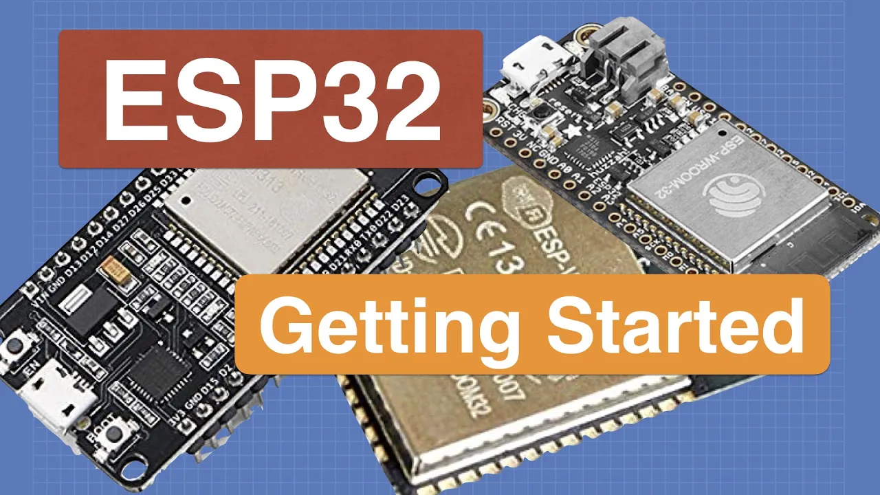
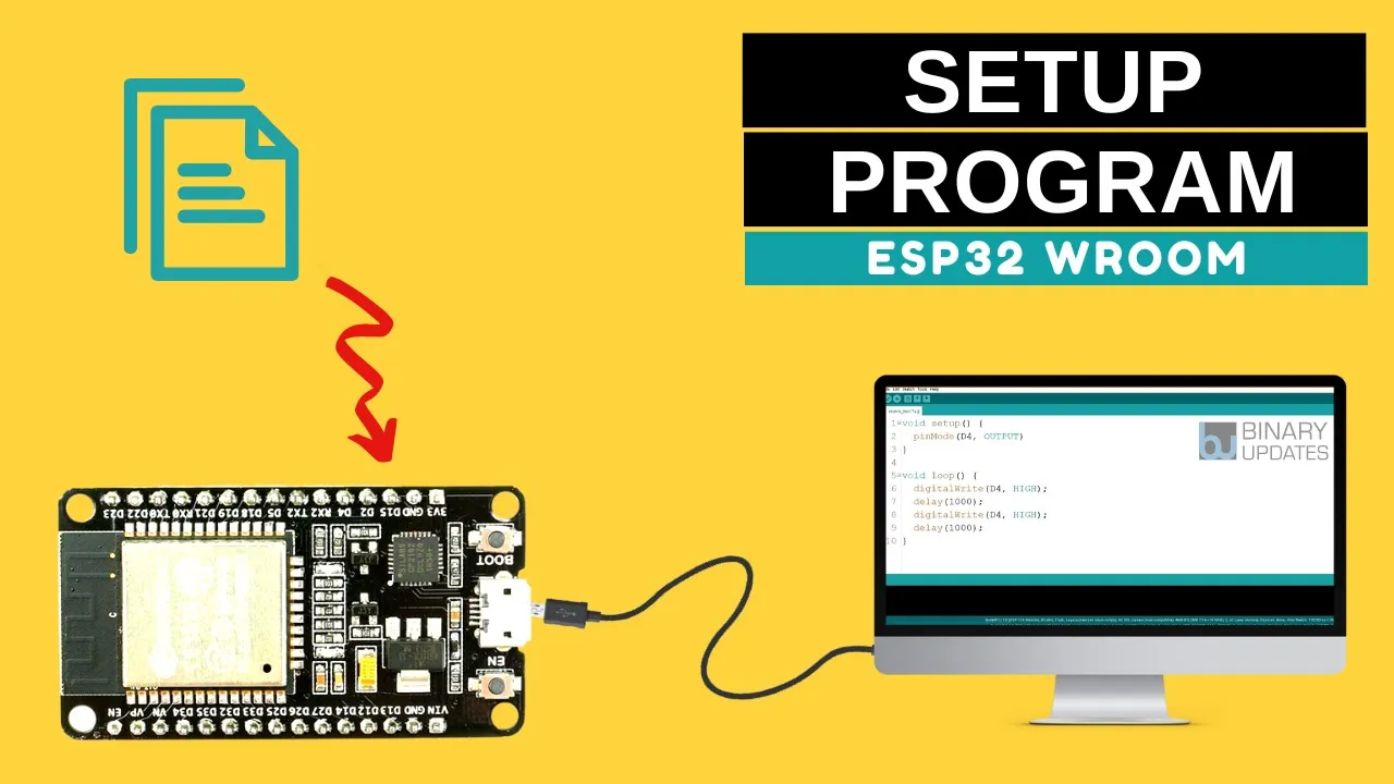

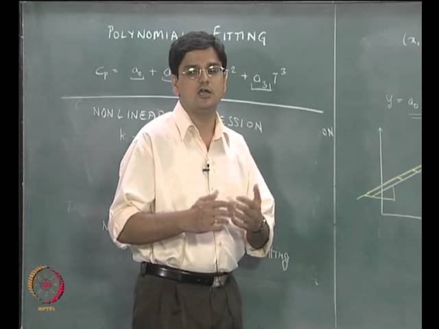










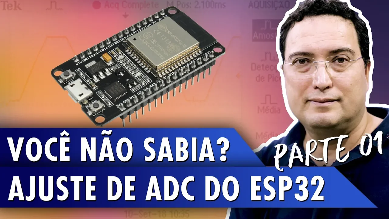


The ESP32 microcontroller features a versatile 12-bit analog-to-digital converter (ADC) with configurable parameters including resolution (9-12 bits), attenuation settings (0dB, 2.5dB, 6dB, 11dB), and sample averaging, allowing developers to optimize trade-offs between input range, accuracy, and conversion speed; however, due to inherent non-linearity in the ADC response, particularly at the extremes of the input range, a polynomial correction function can improve measurement accuracy to less than 1% error by mapping raw ADC readings to corrected voltage values.
ESP32 ADC Guide: Advanced Functions, Accuracy & Calibration
Added:Basic understanding of analog versus digital signals, including voltage, noise, and how microcontrollers interface with physical environments.
Fundamental concepts of Analog-to-Digital Conversion (ADC), including resolution (bit depth), sampling rates, and reference voltages.
Familiarity with the ESP32 microcontroller architecture, GPIO pin mapping, and basic programming using Arduino IDE or ESP-IDF.
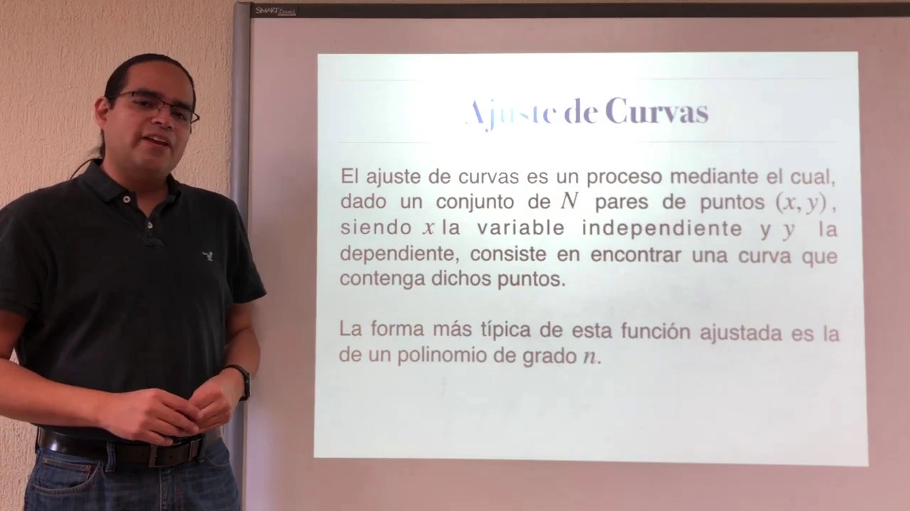
Elementary mathematical understanding of linear equations and polynomial curve fitting for calibration purposes.
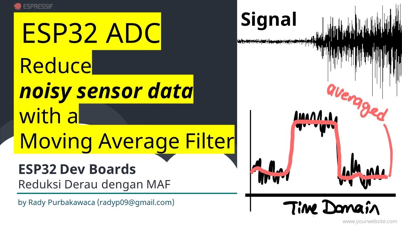
Implementation of software-based digital signal filtering techniques, such as moving average or Kalman filters, to mitigate high-frequency noise on ESP32 ADC channels.
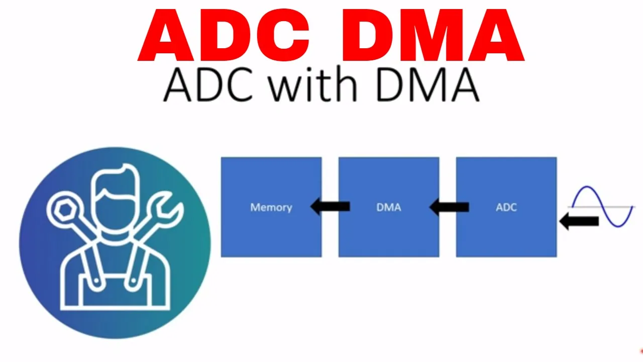
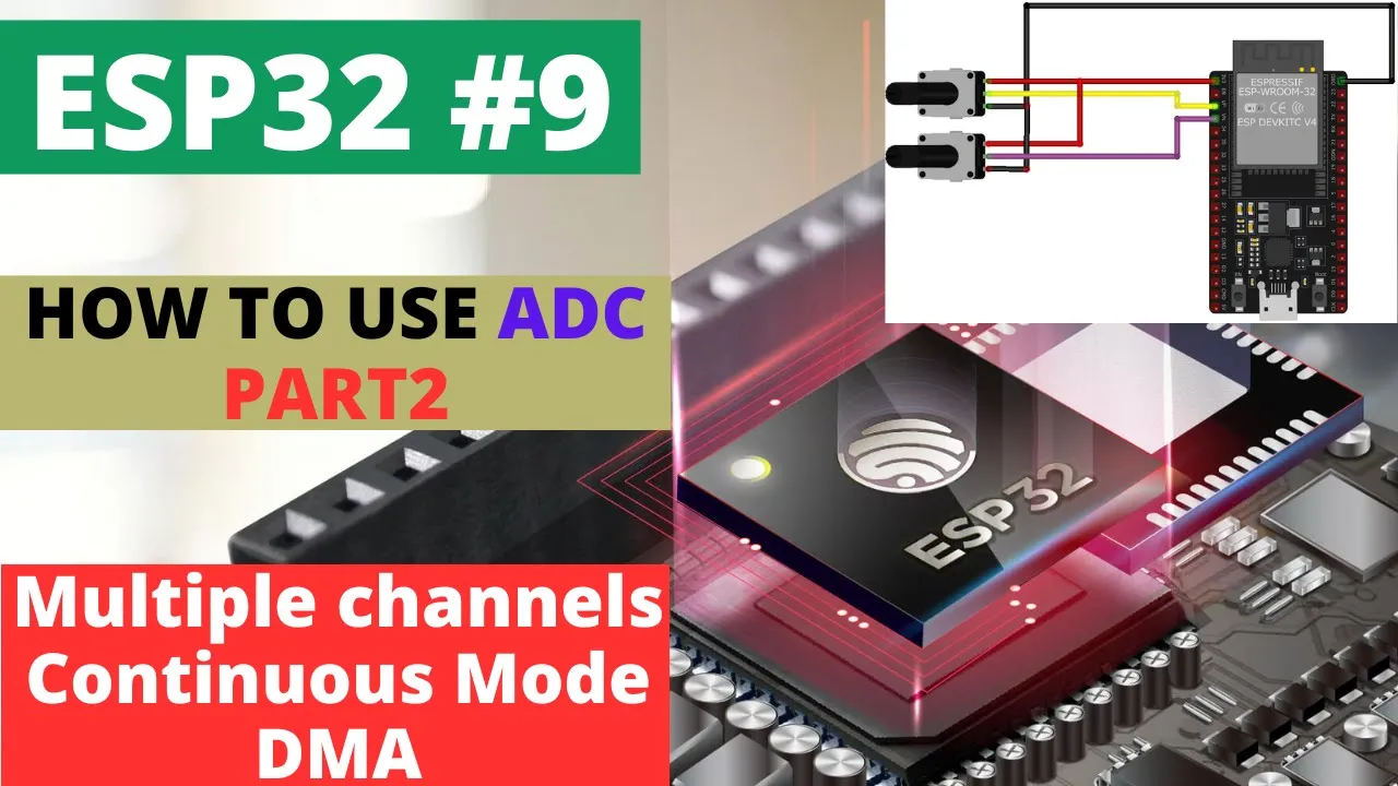
Utilizing the ESP32's Direct Memory Access (DMA) controller to achieve high-speed, non-blocking continuous ADC sampling.
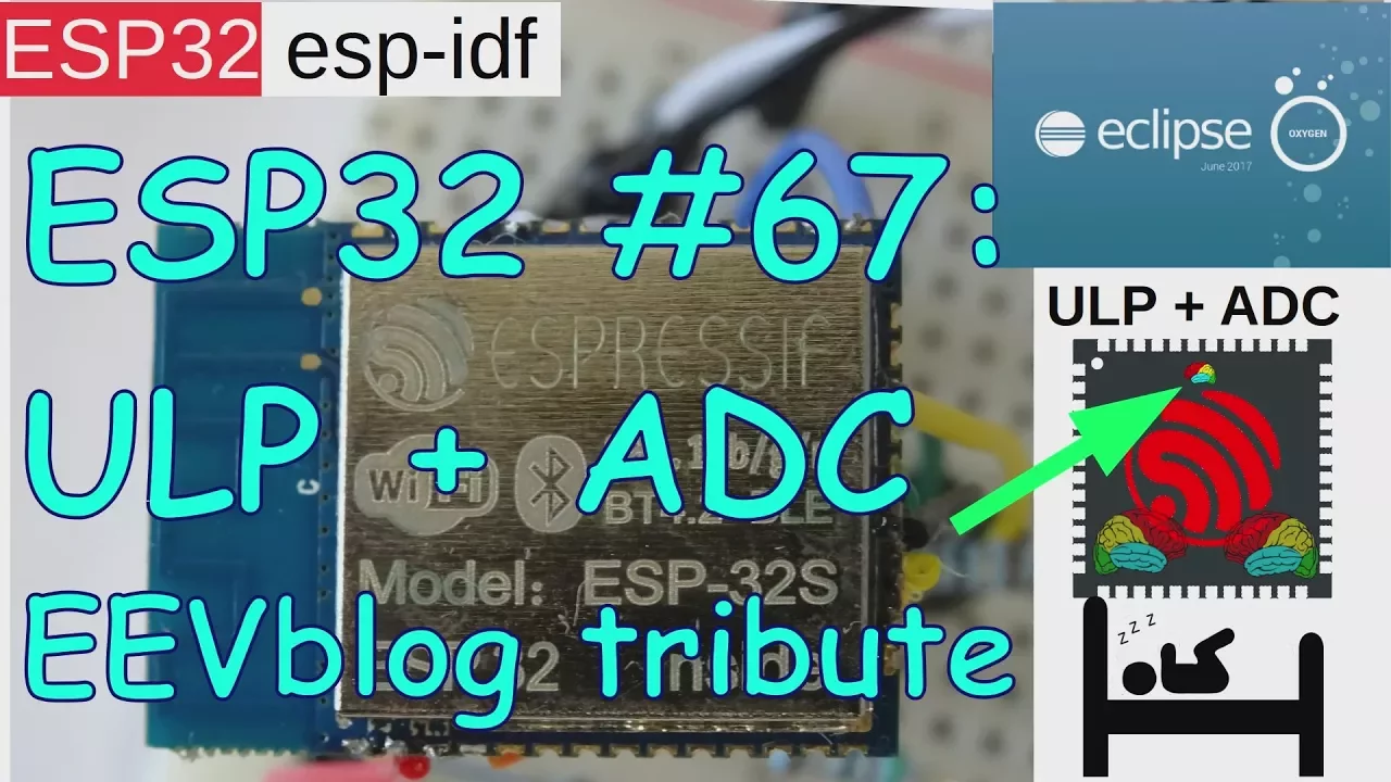
Programming the ESP32's Ultra-Low-Power (ULP) co-processor to monitor analog sensors while the main CPU remains in deep sleep.
Applying advanced calibration techniques to non-linear analog sensors (such as NTC thermistors or pH probes) using the calibrated ESP32 ADC.
76.5K views1.3Klikes6:52Original Release: 2017-11-14
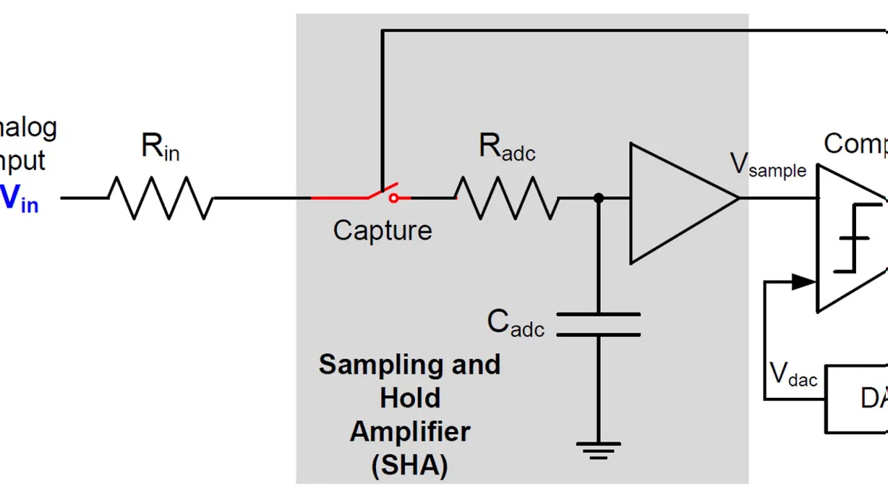
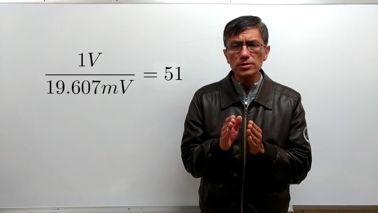
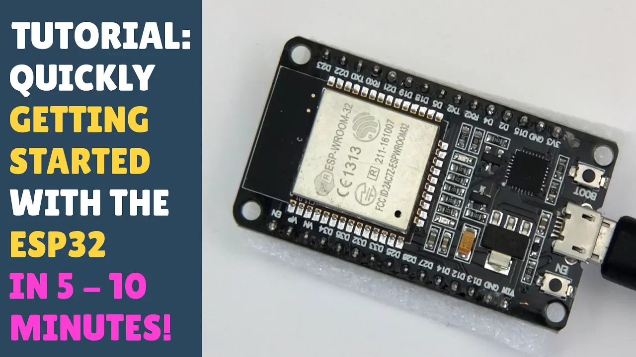
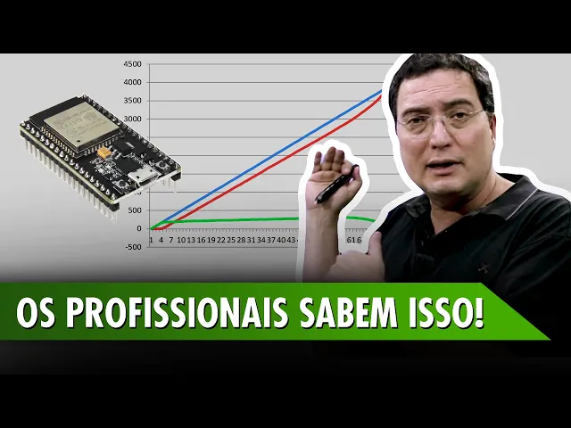
hello folks in this video I aim to go through the basics of using the ESP 32 analog to digital converter and I also look at some of these features those are the two main inputs you'll find on most development boards the P and V n GPO 36 and 39 respectively so typical inputs are VP GPO 36 shown there on the board the low limb board and VN GPO 39 you can use any of 12 other pins for the ADC inputs so you can reassign the ADC channel to another pin and you can change the inputs the resolutions and essentially the accuracy of the ADC converter that's my test arrangement which is a 10k pot connected between three volt 3.3 volts and ground and the input is going to VP GPIO 36 in this basic form it's very easy to use and dope no need to define the input pin I'm using pin 36 or VP I've used two examples there the result is analog read 4 6 4 4 1/2 for not 0.5 volt input to pin VP this is the typical linearity of the of the input range the ADC the green line denotes an ideal response so for 1 volt 1 to 5 Oh cam and 2 volts 2500 cam the actual response is the red line that I'm depicting and has a linear region from about naught point 5 volts to 2.5 volts it's not Linnaeus god that's too little dog legs at either end but with a range of nought to three volts workable not not linear but workable these are the range of functions you have available to you the analog read resolution defaults to 12 bit but can be varied from 9 10 11 or 12 so 12 bit is nought to 4095 count set the width of the analog-to-digital channel both the sample bits and therefore the read resolution again from nine to twelve bits set the number of cycles per sample default is eight set the number of samples number of samples taken per cycle one two three up to 255 set the clock or the speed of the analog to digital conversion set the attenuation these are the labels you have to use ADC underscore 0 DB 2.5 DB 6 DB and 11 DB and you can set the attenuation on a particular pin so I'll go through a little bit more detail later but the labels are always the same for the attenuation setting are the 11.3 for 1.5 or 3.6 is the divider attach a pin so attach the ADC channel to pin 13 perhaps there's a couple of three functions for testing the status so start the conversion check that it's busy and chamber this ended these are three four sorry these are the four ranges with different attenuation settings either 0 2 point 5 6 or 11 in essence with zero DB which is this curve here the range is 1 volt input 1 volt is - 4095 96 counts so always assume naught to one volt is this default range and you can vary the attenuation to get a wider range but with lower resolution but noting that the 11 DB range the default range whilst giving a nice wide input range he's not quite linear here's an example of attaching the ADC channel to pin 13 reading that pin and getting the same result here's an example of setting the clock speed so that's its default value anyway and discounting the serial print statements it takes approximately four hundred microseconds to where to make the conversion so start the timer get a timer reading and then undertake the conversion print the result and there's the answer same thing there now with 255 a value of 255 takes 775 Mike sings so it has the effect of slowing down the conversion I talked about the result being nonlinear well I've created a function here which I'll put on github which is called read voltage with the pin number 36 what it is is a polynomial equation that takes an input voltage takes the REA DC reading and conversely a DC reading back to a straight line so that gives you a very accurate for my calculations and my results less than 1 percent error so that's using a bit of mathematical controls to correct the ADC response that's all you need including your program to get a really accurate read voltage overall then the ESP 32 ADC is easy to use you can get a reading with that simple statement default accuracy is approximately two seven percent can be improved you can vary its resolution you can change its pin and you can vary a wide range of ADC parameters when required or for your application enjoy
Up Next

2:30
How a pH Probe Works: Glass Electrode Explained
@OUPAcademic
159.8K views•2013-03-08

12:54
Triumph of Orthodoxy Icon: Byzantine Art & History Explained
@BenCallan
2.1K views•2024-08-06

9:49
FastAPI vs Flask vs Django: Choosing the Right Python Web Framework
@TechWithTim
302.5K views•2024-05-26

1:42
Game of Thrones Opening Credits: A Cinematic Analysis
@gameofthrones
46.3M views•2011-04-18
Related Study Plans & Knowledge Roadmaps
Structured learning paths in General & Interdisciplinary Studies
general-studies
Elevator Engineering: History, Physics & Cities
01From Hoists to Safety Brakes: The Dawn of Vertical Lift
02Hydraulic vs. Traction: The Engineering Physics of Elevators
03Modern Speed, Safety, and Algorithms
+ 2 more learning modules
12h5 modules
Explore Roadmap
general-studies
Rubber: Material Science, History & Geopolitics
01Origins of Natural Rubber & Mesoamerican History
02The Chemistry of Natural Rubber & Vulcanization
03The Geopolitics of the Rubber Boom & Colonization
+ 2 more learning modules
12h5 modules
Explore Roadmap
general-studies
Containerization: Evolution, Logistics & Trade
01Ancient Trade & Bulk Cargo: Amphorae to Barrels
02The Industrial Revolution & Cardboard Packaging
03The Containerization Revolution: Malcom McLean
+ 2 more learning modules
12h5 modules
Explore Roadmap
general-studies
Textile Tech: Evolution, Labor & Global Impact
01Pre-Industrial Textiles: Handloom & Cottage Industry
02Mechanization: The Spinning Jenny to the Power Loom
03The Factory System & Global Labor Transformation
+ 2 more learning modules
10h5 modules
Explore Roadmap