






![[임베디드 입문용 39-1] ADC는 이렇게 쓰세요](https://i.ytimg.com/vi/lA_sX0Apswo/maxresdefault.jpg)


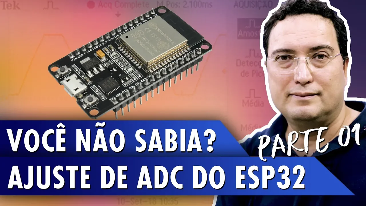



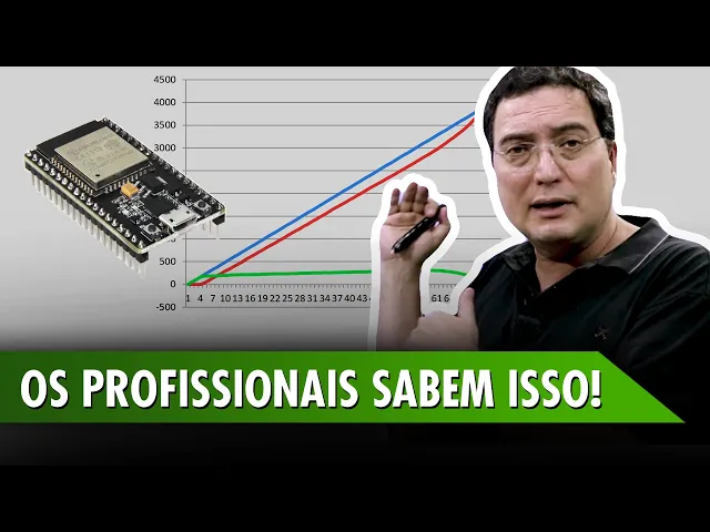
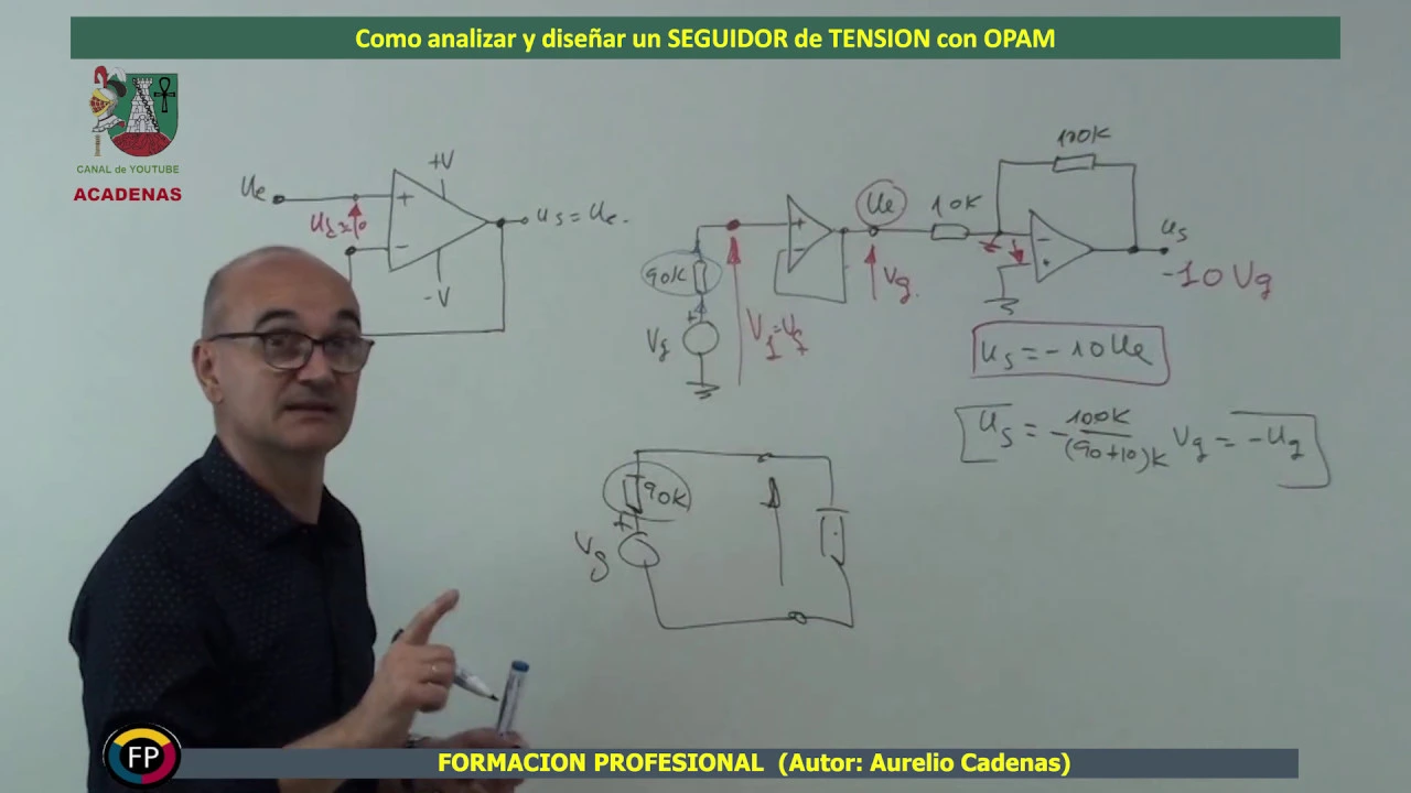
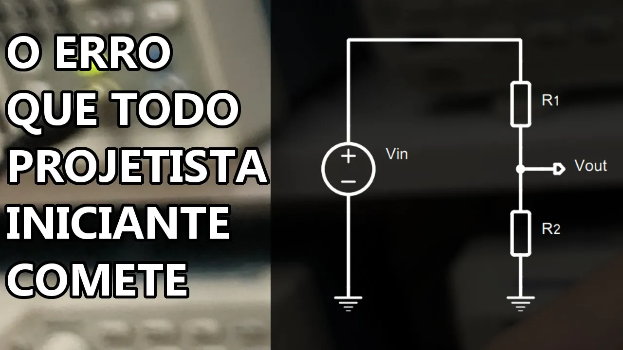










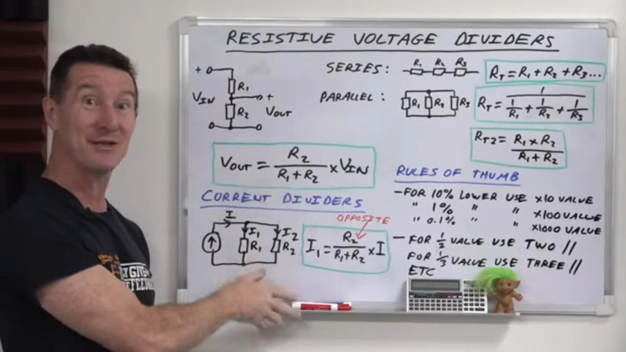
The ESP32's built-in ADC has a maximum input range of 3.3V, but this can be extended to measure higher DC voltages by using a voltage divider circuit (Vout = Vin × R2/(R1+R2)), where the divided voltage must not exceed 3.3V. Since standard resistors come in preferred values rather than exact calculated values, software compensation is necessary to improve measurement accuracy. The ADC has an input impedance of approximately 200kΩ, so external circuitry should have lower impedance. Additionally, the ADC exhibits nonlinearity above 3.3V, making it important to keep input voltages within the linear range or apply proper voltage division.
ESP32 ADC Voltage Measurement: Extending DC Range with Dividers
Added:Basic DC circuit theory, specifically Ohm's Law and how voltage behaves in series and parallel circuits.
The fundamental formula and operation of a passive resistor voltage divider.
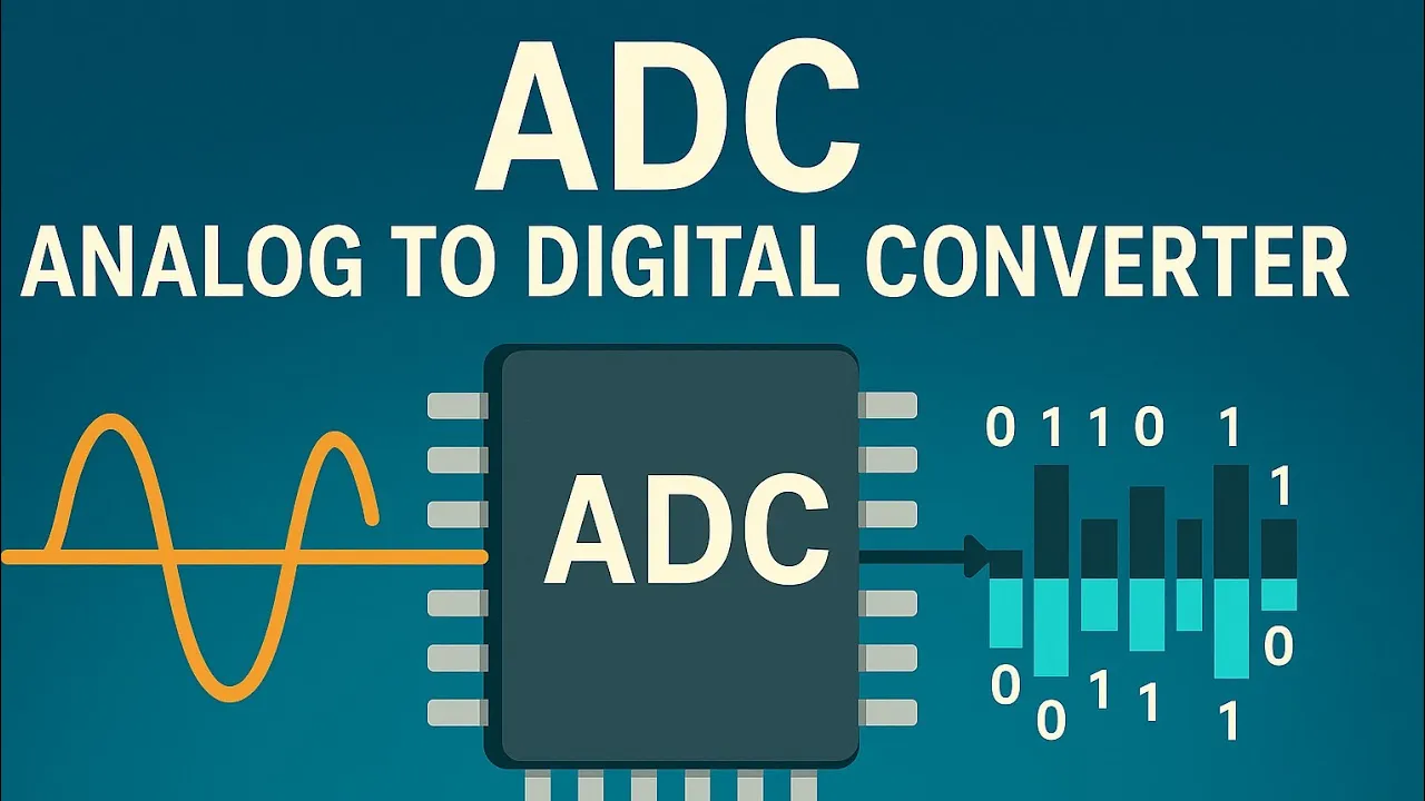
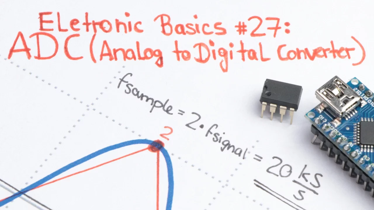
The concept of Analog-to-Digital Conversion (ADC), including resolution (e.g., 12-bit) and reference voltage limits.
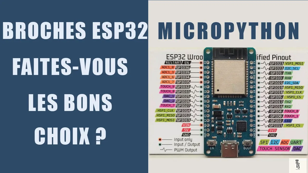
Familiarity with the ESP32 hardware specifications, specifically its standard 3.3V operating voltage limit on GPIO pins.
Calibrating the ESP32's ADC to compensate for its inherent non-linearity and hardware-specific offset errors.
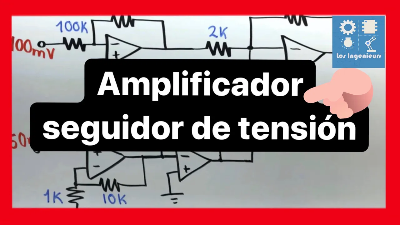
Using Operational Amplifiers (Op-Amps) as voltage followers (buffers) to prevent impedance loading effects on high-resistance dividers.
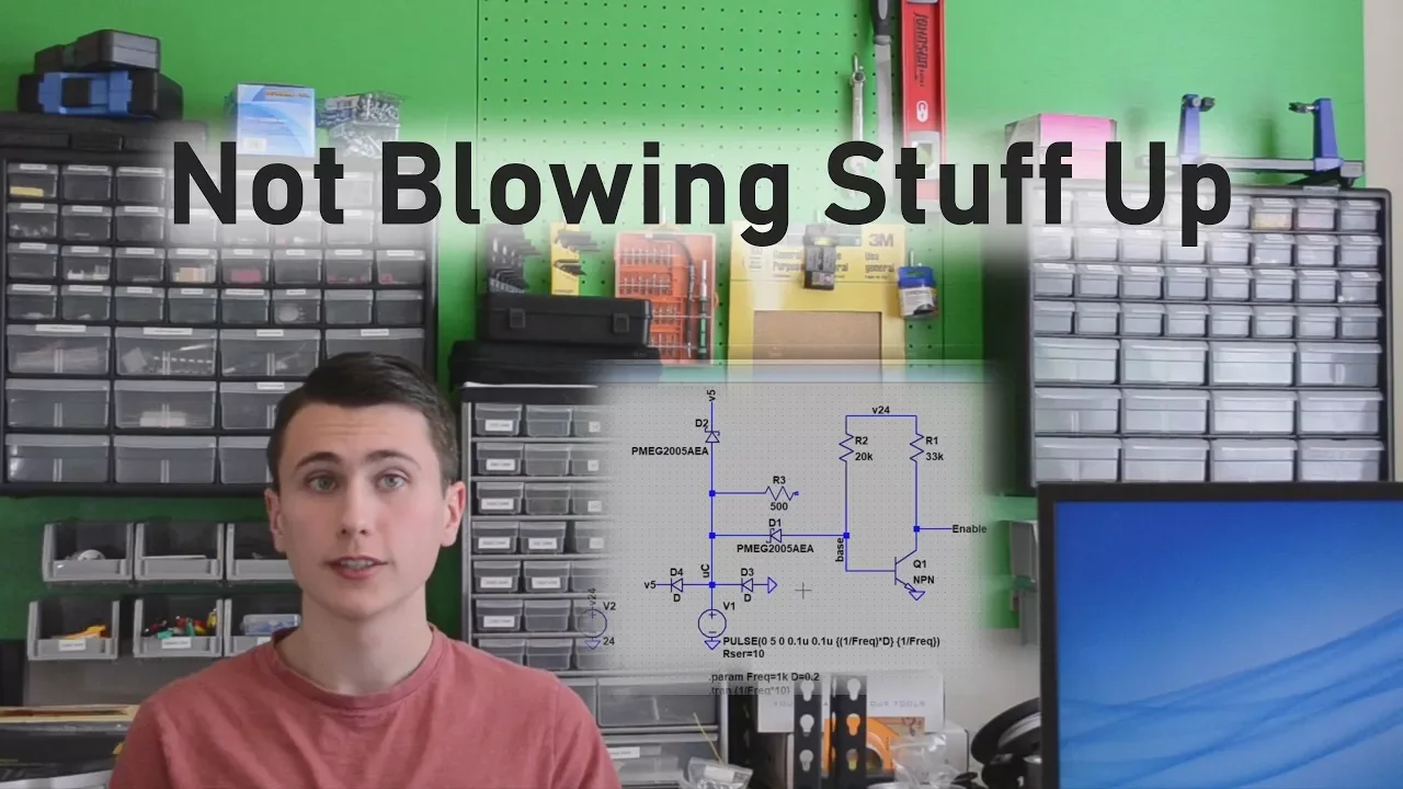
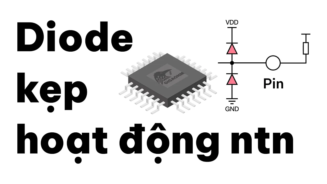
Implementing overvoltage and transient protection circuits, such as clamping diodes, to protect ESP32 pins from voltage spikes.
Applying signal conditioning techniques, including hardware RC low-pass filters and software averaging algorithms, to reduce measurement noise.
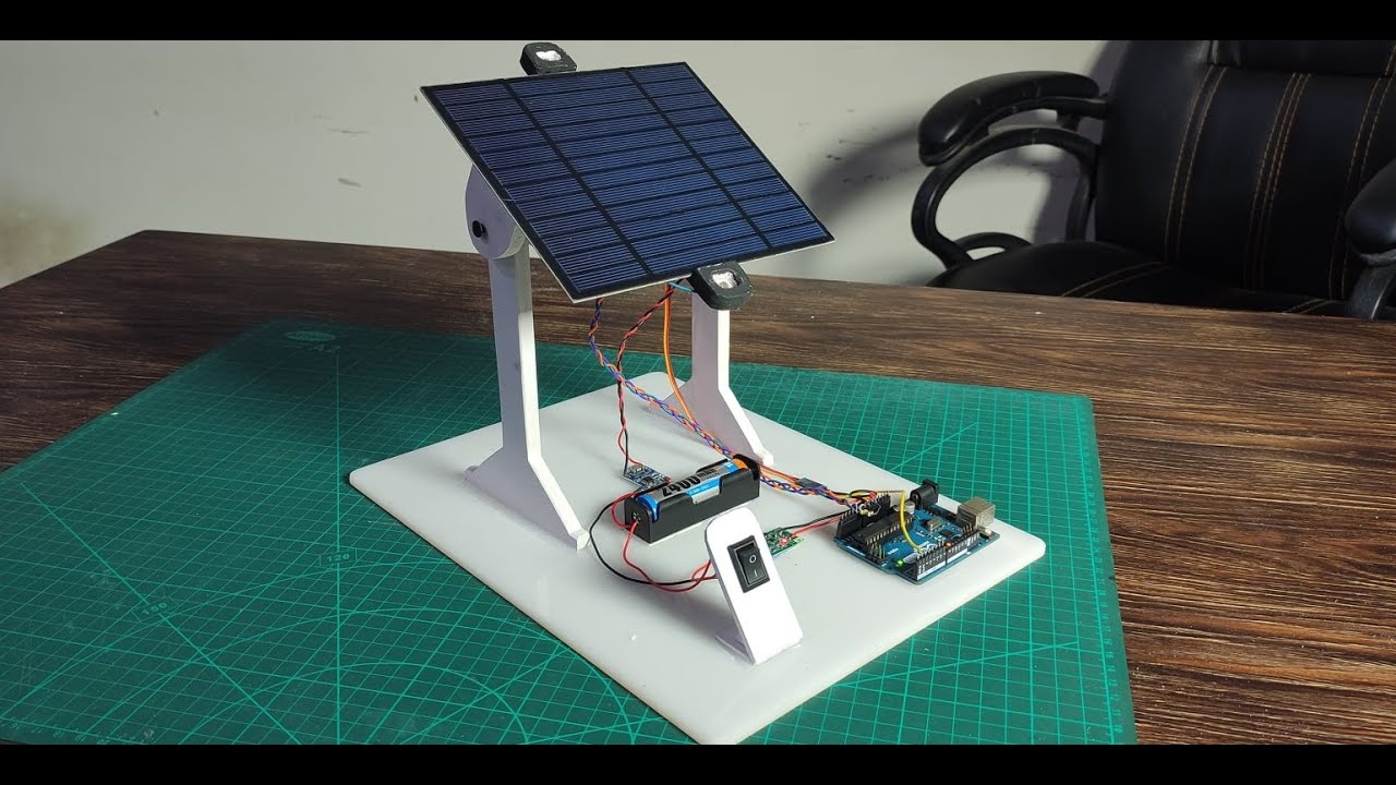
Developing practical telemetry projects, such as LiPo battery state-of-charge monitors or solar panel voltage tracking systems.
85K views1.8Klikes8:11Original Release: 2019-01-15
hello I'm Dave welcome to my technical notes channel in this technical note I'm going to look at how you can use your ASP 32 as a wide-ranging voltage measuring device to begin with a reminder that the basic analog to digital converter voltage input is VD D which is 3.3 volts - a nominal 0.3 volts so ideally naught to 3 volts for a linear measurement but it will actually measure naught to 3.3 volts so it's basic measurement range is 3.3 volts and there's an expression there float voltage equals analog read on pin 36 divided by 4096 the default resolution times 3.3 volts is a 3.3 volt voltage meter some more reminders that if you on the left hand side if you put into the ADC 3.3 volt its range is 0-2 4095 you'll get a reading off 4095 in the middle if you put in half of that voltage you'll get approximately half the reading or 2047 or if again if you scale the display output with a value a range value you'll get a voltage so analog read on pin 36 divided by 4096 which is a naught to 4095 forget the numbers times 3.3 will give you a voltage output this case one point six five volts how do we extend the voltage range we add a voltage divider where V out equals V in times r2 divided by r1 plus r2 and the out should not exceed three point three volts which is the max of input to the analog to digital converter so voltage dividers reduce input voltage to a desired value so a hundred volts down to three point three volts so here I've done the wiring for measurement of a 13.8 volt power supply and I've chosen in the range to be naught 15 volts and using a hundred K value for r1 and a 27k for r2 and showing that on the serial monitor you'd get a reading of 13.8 volts which is what you'd expect using GPIO 36 throughout all of these examples otherwise known as VP or the N which is GPIO 39 on most boards so to make the calculation easy it's better to go to an Ohm's law calculator if you do that and I'll put a link in below and in this design example enter 15 volts for the voltage source and 3.3 for the required output voltage and choose any value you'd like but I tend to use a hundred K for resistor R 1 calculate press the calculate button the answer is 28 point two oh five K or twenty eight thousand two hundred five ohms that's an exact value the next one we come to is that resistors are only sold in what's called preferred value ranges east 63 range typically so what we need to do is translate the 28 205 ohm absolute value to the nearest preferred value well that begins with 27 so we'll use 27 K ohms that's the value we should use a hundred K and 27 K in a voltage divider and now we need to do is to compensate in the software for that ratio which is 28 205 over 27 K and then we'll get to instead of three point one nine volts we'll get a value of 3.3 volts and that improves the accuracy of the voltage reading that we're using so here's a short example how to do that so again voltage equals analog read on pin 36 divided by the resolution in this case the default resolution is 4096 multiplied by the voltage range so we're working out how to make an or 215 or reading 15 and then compensate for the actual value calculated divided by the preferred volley so required value divided by the preferred value and that gives you a very a very accurate result so here's some examples for a naught to 5 volt reading 100k and 200k for a 12 volt maximum reading 100k and 39k in both cases with compensating values in the analog read statement it's like compensating for the preferred value over the actual value and here's a couple of more examples for 24 volt maximum input 100k and 16 K again compensated and also hundred volts noting that when of DC voltage gets above sixty volts it becomes hazardous to the human body so if you're doing this you really should know what you're doing and be very careful about touching any life components so in summary then the default resolution of the ADC channel is 4096 the input impedance of the ADC is approximately 200 kilohms which I determined by applying a fixed input voltage and then gradually increasing the input impedance until the ADC reading had dropped to half and so i know that the external and the internal impedance are about the same not a terribly accurate way of measuring input impedance but it gives you an idea of what the input impedance is likely to be so your external circuitry should always be of lower impedance than 200 K and indeed most development boards do use values which are lower than 200 K compensate for preferred value resistors so to improve reading accuracy be careful or ideally don't measure voltages of more than 60 volts DC unless you you feel safe to do so and also see my tech note 69 for methods that mathematically using a polynomial improve ADC linearity so the ADC is quite linear between naught and three volts above three volts it tends to become Mark Abilene nonlinear so what do I mean by nonlinear if you put in three point one volts you might get a reading of three point zero five volts and if you put in a reading of three point two you might get a reading a three point one and so on I hope you found this useful I hope you found this technical note interesting and useful
Up Next

22:25
Relay Wiring Guide for Automotive Electrical Projects
@MotionRaceworksOfficial
306.6K views•2020-04-28

30:32
Ultrasonic Transducers: Resonant Frequency Measurement and Horn Design
@imajeenyus42
229.9K views•2017-02-22

54:16
Polymer Environmental Degradation: Mechanisms & Stabilization
@iit
1.8K views•2012-07-10

33:39
How a Student's Question Saved a NYC Skyscraper from Collapse
@veritasium
22.8M views•2025-04-26
Related Study Plans & Knowledge Roadmaps
Structured learning paths in Engineering
engineering
Building Acoustic Levitators: Physics & Arduino
01The Physics of Sound and Standing Waves
02Piezoelectric Transducers and H-Bridge Drivers
03Arduino Programming: Generating 40 kHz Signals
+ 2 more learning modules
14h5 modules
Explore Roadmap
engineering
Building Peltier Cloud Chambers: Particle Tracks
01Cosmic Rays & Cloud Chamber Physics
02Thermoelectric Cooling (TEC) Fundamentals
03Custom Liquid-Cooling Loop Design
+ 2 more learning modules
18h5 modules
Explore Roadmap
engineering
Yagi-Uda Antennas: Modeling, Build & VNA Test
01Introduction to RF and Antenna Fundamentals
02Yagi-Uda Antenna Design Principles
03Antenna Modeling and Simulation in 4NEC2
+ 2 more learning modules
18h5 modules
Explore Roadmap
engineering
ECG Monitor Design: Op-Amps, Filters & Noise
01Electronics & Breadboard Basics
02Op-Amps and Instrumentation Amplifiers
03Bioelectricity and ECG Fundamentals
+ 2 more learning modules
18h5 modules
Explore Roadmap