![Regulatory PID [RS Elektronika] #158](https://i.ytimg.com/vi_webp/ecOGDeYjt0M/maxresdefault.webp)





















![Little Guys 9: The First Of Many [Intertel Axxess]](https://i.ytimg.com/vi_webp/tbSl0GREN9k/maxresdefault.webp)


This video demonstrates how to build a two-wheel balancing robot using an LG XBOOM Go speaker as the head, featuring an aluminum and 3D printed frame with belt-driven wheels powered by motors controlled by a Teensy 3.6 microcontroller running a PID algorithm that uses data from an MPU 6050 inertial measurement unit to maintain balance; the key insight is that PID controllers for balancing robots typically require very high proportional (P) values (often ten times higher than derivative values) to enable rapid acceleration toward the upright position, with the D value used to dampen oscillations and achieve stable balancing.
Two-Wheel Balancing Robot with LG XBOOM Go: Build Tutorial
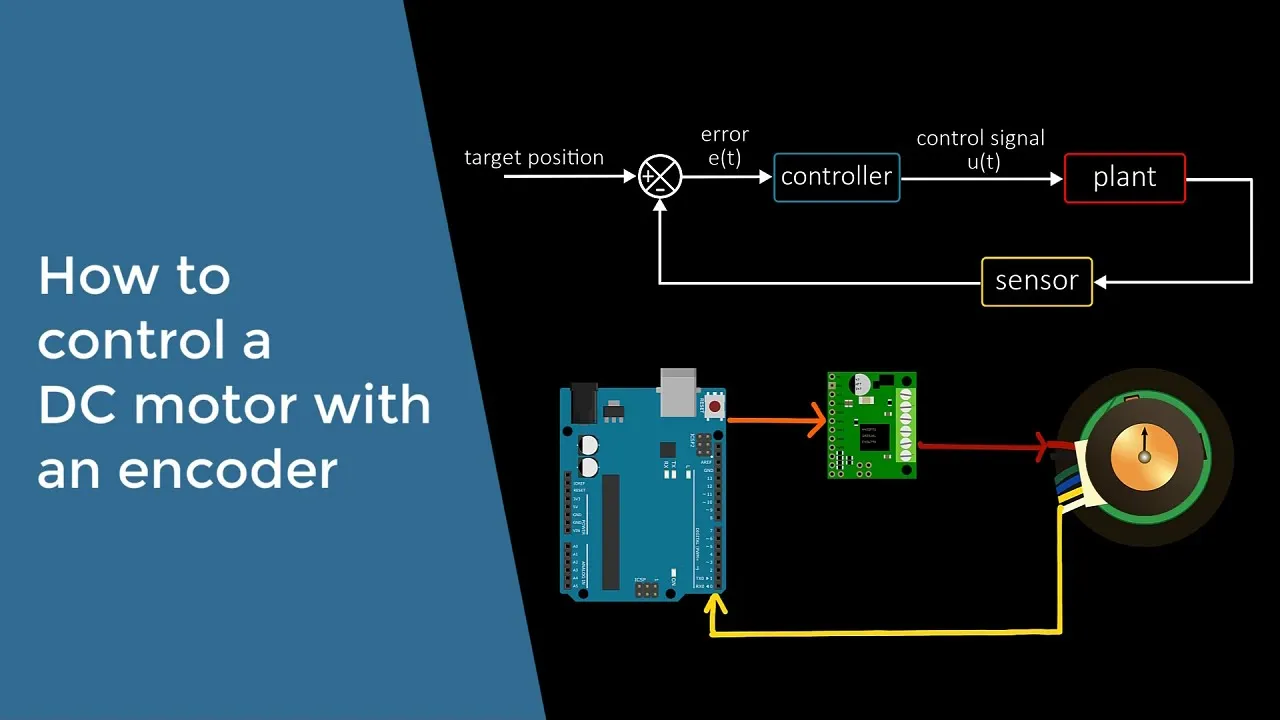
Added:Basic PID Control Theory: Understanding feedback loops, error calculation, and tuning parameters (Kp, Ki, Kd) for system stabilization.
Microcontroller Programming: Familiarity with C/C++ programming and hardware interfacing (I2C, SPI, PWM) using platforms like Teensy or Arduino.
Inertial Measurement Units (IMUs): Knowledge of how accelerometers and gyroscopes work, along with basic sensor fusion techniques (e.g., Complementary or Kalman filters) to estimate tilt angles.
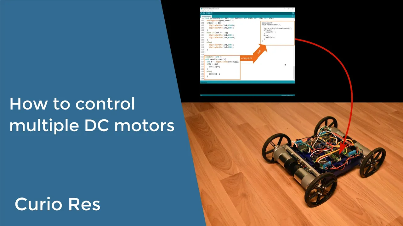
DC Motor Dynamics and Encoders: Understanding how H-bridge motor drivers control speed/direction and how rotary encoders track wheel position and velocity.
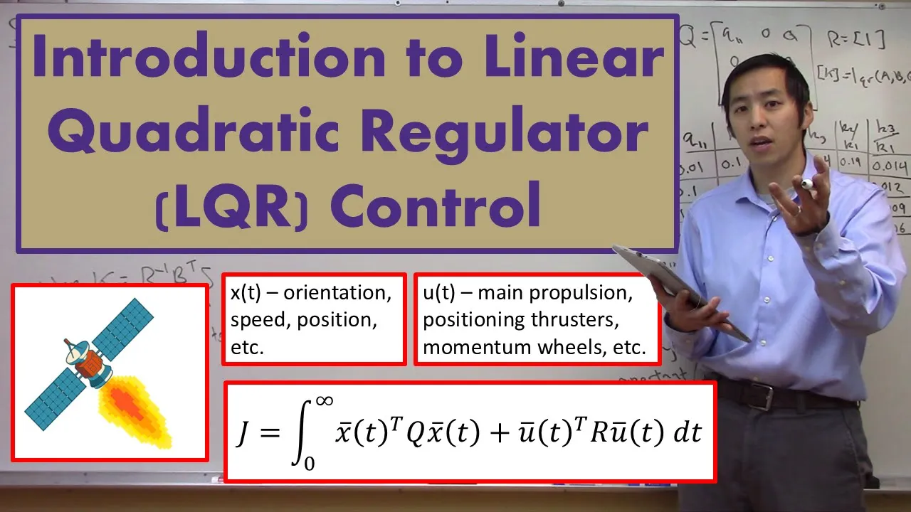
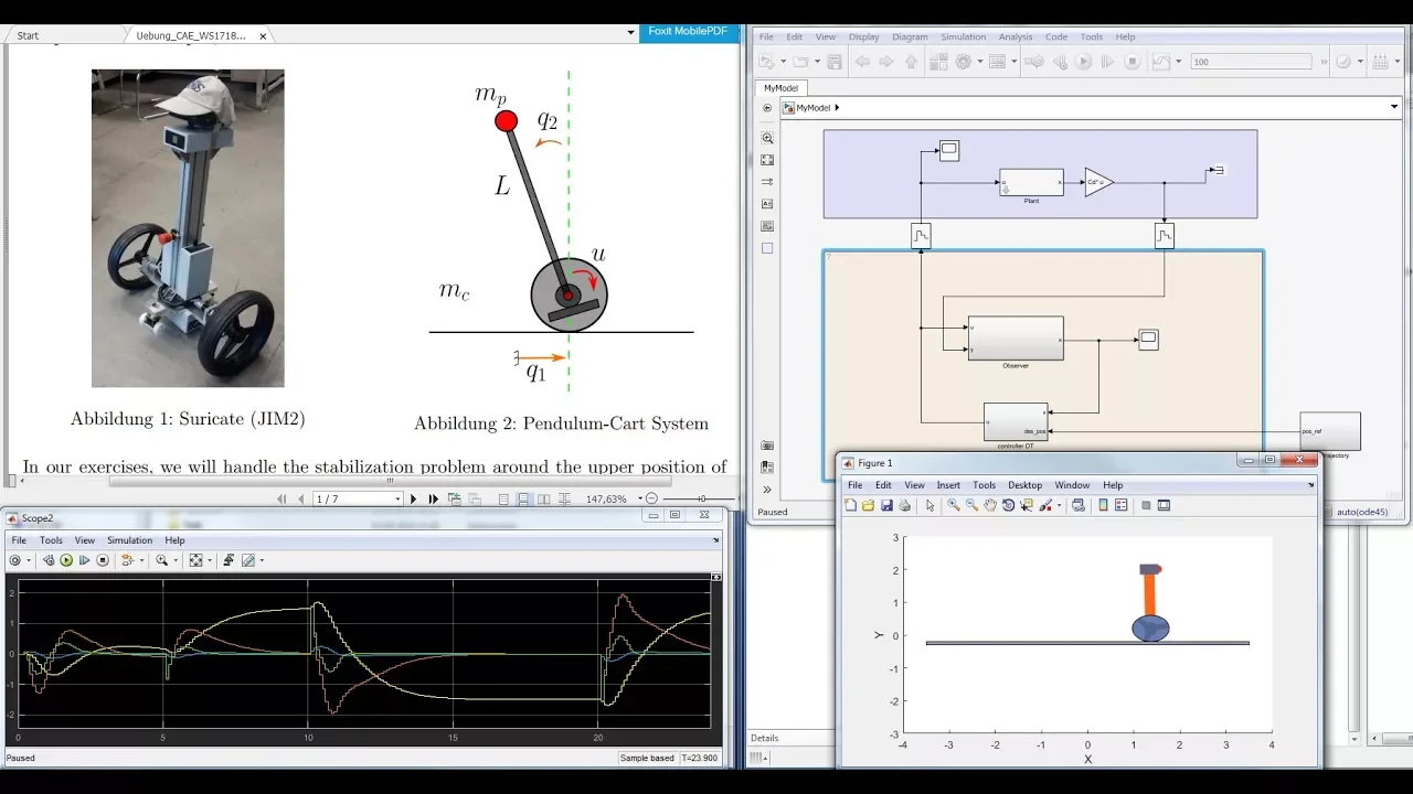
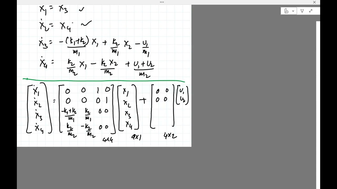
State-Space Control and LQR: Transitioning from standard PID to Linear Quadratic Regulators (LQR) for more robust multi-variable control of the inverted pendulum system.
Dynamic System Modeling: Deriving the mathematical equations of motion for self-balancing robots using Newtonian or Lagrangian mechanics.
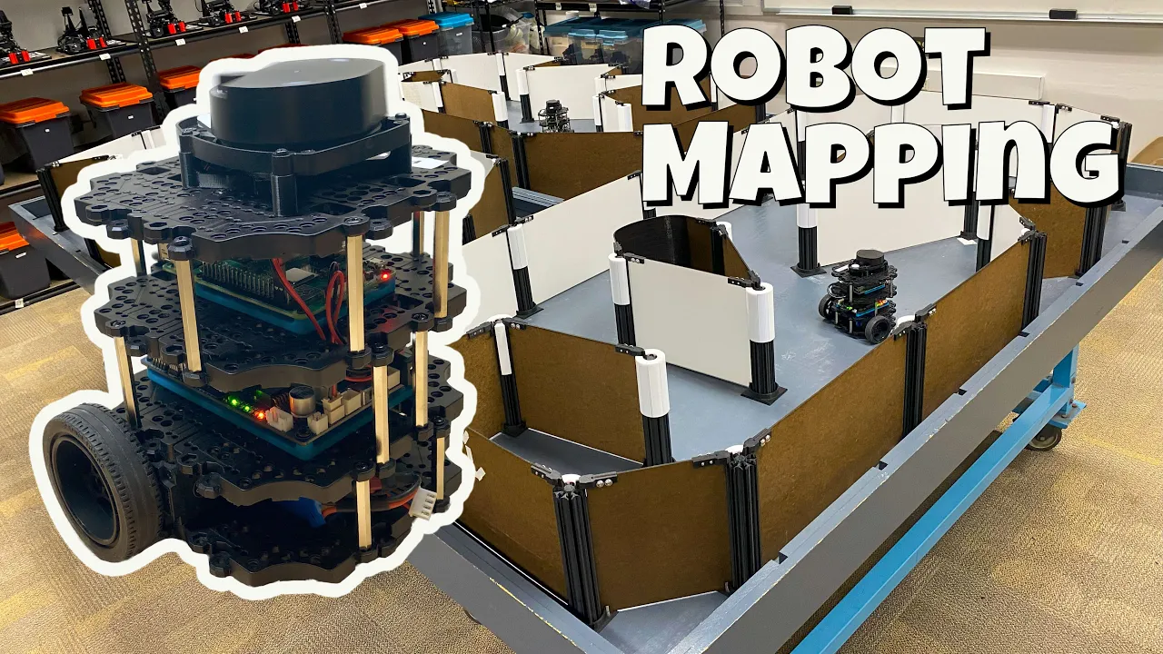
Autonomous Navigation and SLAM: Integrating sensors like LiDAR or depth cameras with ROS (Robot Operating System) to enable mapping and obstacle avoidance.
Embedded DSP and Real-Time Systems: Optimizing the control loop execution using Real-Time Operating Systems (RTOS) and advanced digital signal processing.
100.8K views3.5Klikes14:33Original Release: 2019-07-09
hello this is a robot project but it's sponsored by LG's ex boom go Bluetooth speakers so I get asked to review a lot of Bluetooth speakers in this channel but normally I don't do any of them but these are pretty good as a good brand because it's LG these speakers all support an Iridium technology which is this complete control over the audio signal so it sounds exactly how it's supposed to and Meridian technology is used in the latest Land Rovers and Jaguars so these are Bluetooth speakers but they have high fidelity sound quality and in fact they support 24-bit which is higher quality than a CD the larger speakers the PK 5 and the PK 7 both have lights in to light up your party and those lights react to the music as it's playing the PK 7 has dual tweeters and all of these speakers have dual action base and the PK 3 if you've got more than one of these speakers you can use the dual play feature to pair them together and that means you can get stereo sound out of each of the speakers they've also all got this voice control button which allows you to link them to your smart phone for voice control be it Siri or an Android voice controlled app all of these speakers are splash proof and the PK 3 apparently can be completely submerged these have pretty good battery life as well so 12 hours 18 hours and 22 hours on the PK 7 which is pretty good for a Bluetooth speaker so this range of speakers has received a 4 star review from both tech radar and trusted reviews so these look a bit like a robot head don't they we 2 eyes in them so LG have asked me can I make a robot with one of these as his head so I'm going to use the PK 7 the big one to make a two wheel balancing robots and that's going to look something like this we're going to use the PK 7 for his head that's about a foot long so the whole thing is about 3 feet tall it's got quite big wheels it's got lots of body panels it's going to have an aluminium and 3d printed frame inside 2 motors with 2 belt driven wheels and obviously it's going to balance on those 2 wheels using an inertial measurement unit and some code running on a teensy 3.6 [Music] [Applause] [Music] [Applause] [Music] [Applause] [Music] [Applause] [Music] so here's my aluminium frame all aluminium plates and extrusion and we've used tea nuts and bolts to attach everything so that's extremely rigid indeed down the bottom we've got a hole there to allow an axle through so we need to 3d print the part that's gonna grab the axle and we've also got these plates which are going to hold the motors and those are going to go in sliders the tension up and down and that's going to adjust the belt tension or rather pull it tight to the wheel [Applause] [Music] [Applause] [Music] [Applause] [Music] [Applause] so he printed these blocks to fit in just here and Lowe's we've got a clamp we can put a bolt through and that's gonna hold an axle which is a steel 80 millimeter axle that goes all the way through those holes and we have a motor assembly which is one of these turning G motors which is 149 kV the 63 74 s k3 range we call that on an aluminium plate with a pulley and we've got a 3d printed spacer and we've got the shaft sticking out the back to put the encoder on and that plate fits into these runners which you've got grooves on the inside so that that play can slide up and down and we can go and tension the motor distance between that and the wheel so we've got those blocks bolted in the bottom we've got our motors fitted and those plates have called slide up and down to tension the belt tension and we've got our two motors and we've got encoders on the back which are the eight 192 CPR encoders which you get from a drive robotics which is handy because I'm going to be using an O drive robotics motor driver to drive the motors so that is feeling incredibly rigid and incredibly substantial there's quite a lot of mass to it now those motors and all the plates are in I really need some wheels so that we can get the main mechanical assembly finished [Applause] [Music] so there is one where your hub with half a tire printed and the tire is ninjaflex so it's really flexible and the hub is printed with a 1.2 mil nozzle on the lulzbot more strudel had to change filament halfway through because it's such a big print which is why the middle read but that's incredibly tough so just one more hub to print and three more of those tires so after many hours of printing we've now got two wheels with the four tires on so we've got the bearings encapsulated in the top there and we've also got a t5 pulley which is a separate piece printed with a smaller extruder slotted on so that we can drive the wheel with the motor now we just need to fit that axle get the wheels on and then we can go and put some pulleys and get those tensioned up so my wheels are fade there and obviously the belt driven onto the motors but what we need to do is keep this belt tight so we need to pull these two plates together and we're going to do that with these pair of blocks now one has got a captive nut in the bottom which fits in a little place and that means I can tighten these together and that pulls them together and those are calls bolt on the two plates so those tension is a fitted there's a nut above and below and if you can just see that that allows me to pull what's thumbing up and down and of course that's in the captive nut on the bottom so it pulls those two plates together and tensions on the belt and the belts I'm using they're of course steel tensioning cords and they're eighty-five belts which is the slightly heavier duty version of the t5 so I think that on the whole that should have less backlash than we get in a gear box so that's everything so far we've got the lgx boom p7 speaker which actually going to be a bit higher than that on its neck so it comes to nearly three feet tall and obviously we've got the arms and all the body panels to do but first of all I want to put some electronics in and see if we can get some rudimentary control over those wheels so here's my prototype electronic setup the motor driver is the O Drive 3.5 and that'll drive two motors when you've got one connected for now we've also got one encoder connected to that motor assembly we just built the core I've got teensy 3.6 and we've got an MP u 6050 inertial measurement units and that's also going to make the robot balanced we've also got two of these which are the NRF 24 lo1 and one of those is connected to this mega which is basically going to be the remote control so we're going to receive data from the remote control to drive around and move the arms and that sort of thing but the main balancing is going to be dealt with by the teensy which is a very fast processor at 180 megahertz and it's 32 bits so for now I'm just connect it's a one wheel of the motor and I've just tied the angle of the inertial measurement unit to control the motor speed so if I tip it we'll see the motor moves in either direction obviously we need a pig controller and some tuning to actually make it balance which is the fun challenge of balancing robots but for now I can control our motor and that seems to run perfectly well there's several really important things to consider when building a balancing robot one of those is that the motors can be positioned and velocity controlled really accurately and that's what the O drive is very good at with that 8192 CPR encoder the other one of course is having a good range of speed and a lot of talk so I don't think we can have any problems here that seems to be pretty good and of course we've got that extra mass on top as well which is going to stop that wheel just spinning like you did there so I think there's no problem with the power of the motors I think we're limited to about 10 or 20 amps and we could go up to 40 and we could also go up to 48 volts so we could quadruple the power there I'm gonna start with 24 because I think that's going to be fine to make it balanced and it's not really a racing machine so anyone familiar with my channel will have seen this a number of times before I'm using the I squared C dev lived from Jeff Roberge which you can get on github for the mpu 60 50 with Arduino examples so very similar to open talked episode 20 which I did quite recently we've got an interrupt service routine and we've got an interrupt attached to pin zero and that is the mpu 60 50 saying it's beta is ready and that I am you will combine its accelerometer and gyro data for you and just give you the numbers basically in degrees and we only need to read one axis here so that's interrupt service routine goes to another tab and all that's doing is setting a flag here so that's just saying the IMU data ready flag is set to 1 then further down my main loop we say if that IMU data ready flag is set to 1 then use the Reed angles function and that goes back to the same tab where we do all the MPU 6050 stuff out of the example code to go and get those angles and that means that basically it only ever reads the angles of this specific place in the loop regardless of when the interrupt is triggered and that could be at any time in the code so for now we're just going and typing now to a serial terminal and we're setting the motor velocities now I did quite a lot of stuff in open dog episode 20 about how long the ooop takes and at the moment I do have the ability to throttle it down but the moment I'm throttling it down to zero milliseconds so we can actually see how long the loop takes to read that data read the remote data and write to the O Drive if we have a look in a serial monitor we can see that in fact that's under one millisecond essentially these bits of data from the remote and the end ones here this is the angle of one of the IMU axis and this is the data going out of the O Drive so if I go and tip that board we should see the number getting bigger and we should be to hear the O Drive in the backgrounds ramping that axis all the way up and we still only got one millisecond of course we're only doing two o Drive writes to the two axis of the O Drive although I have clocked my o Drive up to half a megabit but I don't think the results would be much low if we use the default 115 Killa board so I've put my electronics on this board this is a piece of perma proto board which is like a breadboard but it's actually got solder connections so you can transfer your breadboard design onto it really easily so I've got the team C the MP u 60 50 that's soldered down tight so never shifts and we've got the little remote chip there on a socket and a cable for the serial line which goes off to the O Drive that one I've shortened all the cables and was also called those on the 3d printed basis to fit into the robot so I've made this 3d printed piece of plastic that sits in the bottom and that's gonna hold the battery so that should slot in just in here yep fits perfectly and of course the battery goes in there so we've got the teens he fitted right in the top there and we've called the O drive in the bottom along with the batteries of the leads and nice and short of the motors and the encoders and obviously we've still got that IMU map to them both motor speeds now so no proper tuning yet but um yeah that's looking pretty good yep so that does almost balance actually it needs a proper controller but pretty how you fall those motors are gonna be fast enough and talky enough don't think there's going to be any problems there so yeah there we go won't let it run off the table but that's yeah almost there excellent right I've got the X boom p7 speaker fitted as the head of course 3d printed neck there and the panels are going to fit around that and we've got some little 3d prints that fitted in the back on the front and those are bolted onto the 20:20 extrusion around the back I've got these three clamps which were attached to the neck with screws and we've got some straps that go around the bar or the speaker we've also got some sticky pads underneath to hold the head on so they're also going to be loads of trial and error footage of getting this to balance but it's come up pretty quickly in the end so obviously just with that IMU mapped proportionally to the motor speeds it almost balanced so I've put a pig controller in and it's been really easy to tune up so it's actually pretty stable already it's just balancing on two wheels so pretty happy with that and what we've got is a pig controller where the set points which is actually a little potentiometer in here so I can get it to balance perfectly you can sort of see the speaker isn't perfectly in the middle and it isn't perfectly balanced back to front we've got the input which is coming from the inertial measurement unit so it's that angle and then basically we've got an output which is just driving the wheels eventually will be to steer it by making one won't go fast and will be to make it radio-controlled but for now it just balances trying to keep exactly upright with that set point that's perfectly balanced and now seems to be working pretty well so I'm pretty happy with that and for anyone interested in my pind values what I typically find for balancing robots is that you want an AI value that's extremely high normally ten times that of P and that's because AI helps the robot accelerate towards its target more so that it can balance and catch itself really quickly you need then need to dampen that down with a D value which you can basically experiment with and these probably could go a bit higher still to try and get rid of some of those oscillations and make it a bit more reactive when you push it instead of driving for a long time although there is quite a lot of mass on the robot and you'll notice these values are really really high and that's because the Oh driving coders are 8,192 counts per revolution so to get enough counts per second or per minute to get the velocity we need we need quite a lot amplification on our pit controller but that's the end of part one don't forget to come back in part two where we're gonna put his arms on and those are going to be motorized and also make a controller so that we can drive it all around and then see what we can do with it thanks again to LG for sponsoring this video with their LG X boom go speakers alright that's all for now [Music]
Up Next
18:14
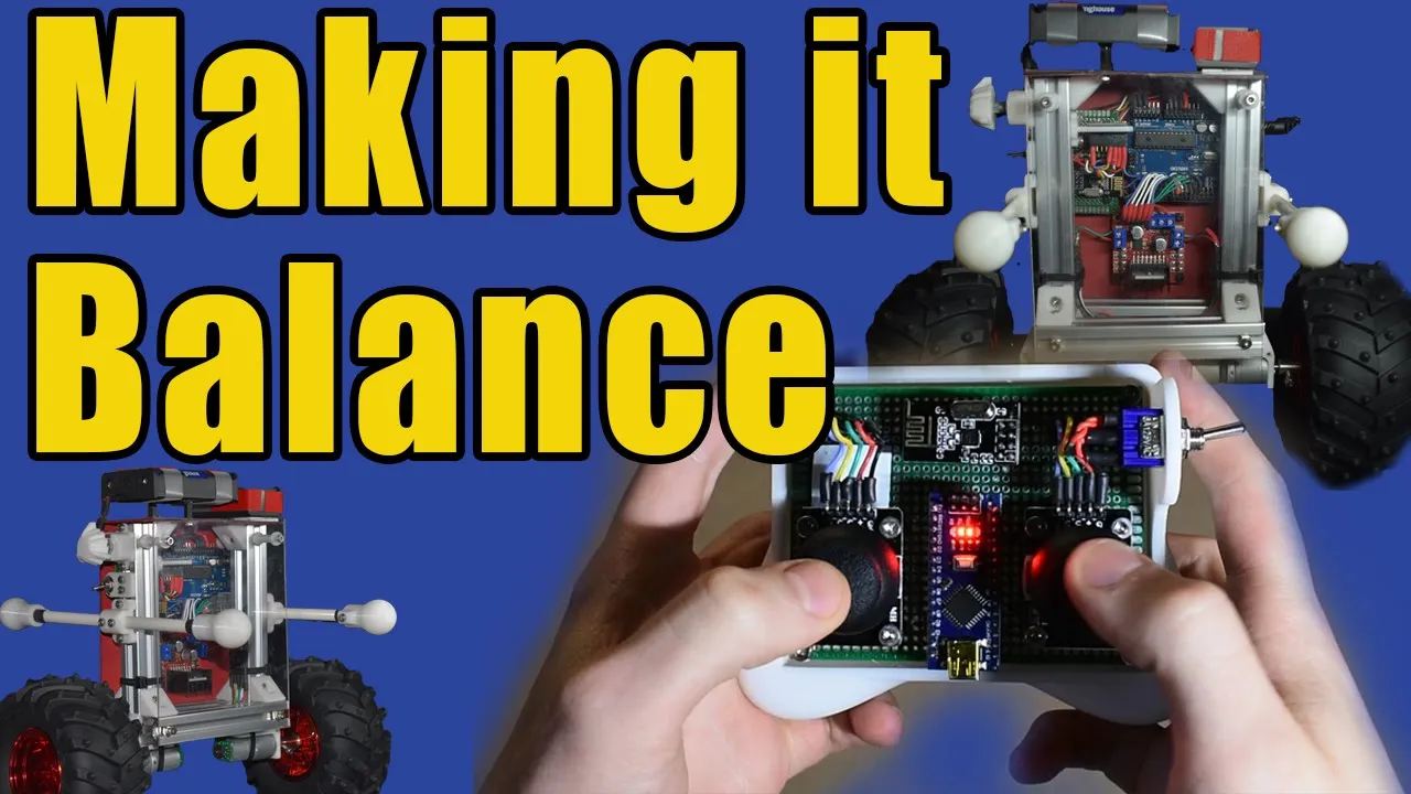
Build a Self-Balancing Robot: Remote & PID Control (Part 3)
@NoahZipin
34.3K views•2020-07-31

58:25
MathWorks Virtual RoboSub Simulation Environment | Webinar 2026
@RoboNationInc
209 views•2026-03-10

13:24
Designing a Ball Balancing Robot: HAL 9000 Build, Mechanics, and Control Systems
@jamesbruton
194.7K views•2020-06-16

25:22
Micromouse: The Fastest Maze-Solving Robots on Earth
@veritasium
23.5M views•2023-05-24
Related Study Plans & Knowledge Roadmaps
Structured learning paths in Robotics
robotics
Building Delta Robots: Kinematics & Pico
01Foundations of Delta Robots & Mechanical Design
02Electronics and Microcontroller Setup with Pi Pico
03Delta Robot Kinematics and Coordinate Math
+ 3 more learning modules
65h6 modules
Explore Roadmap
robotics
Building Ballbots: Dynamics, Kalman & LQR
01Embedded Electronics & Omniwheel Actuation
02Ballbot Kinematics & Rigid Body Dynamics
03IMU Sensors & Kalman Filter State Estimation
+ 2 more learning modules
42h5 modules
Explore Roadmap
robotics
Micromouse: Hardware, PID Control & Flood-Fill
01Electronics & Teensy Microcontroller Basics
02Sensors and Actuators: Motors, Encoders & IR
03Precision Movement: Implementing PID Control
+ 2 more learning modules
35h5 modules
Explore Roadmap
robotics
CDPR: Kinematics, Arduino & Winch Control
01Foundations of Arduino & Basic Electronics
02Stepper Motors and Winch Mechanics
03Kinematics of 2D Cable-Driven Robots
+ 2 more learning modules
28h5 modules
Explore Roadmap