







![[모터 제어] 1. 브러시리스 DC 모터 (BLDC)의 개념](https://i.ytimg.com/vi/xJcPeqOKMvQ/maxresdefault.jpg)








![How to reuse Washing Machine Motors [Arduino vs Basic Triac control]](https://i.ytimg.com/vi_webp/xI6CF2nYf_g/maxresdefault.webp)
![Building an Autonomous Robot From Scratch – Perceptron 🤖| Motor Driver [Ep.04]](https://i.ytimg.com/vi/fgswH4akRd0/maxresdefault.jpg)



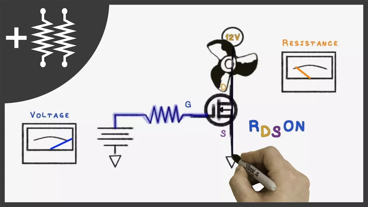
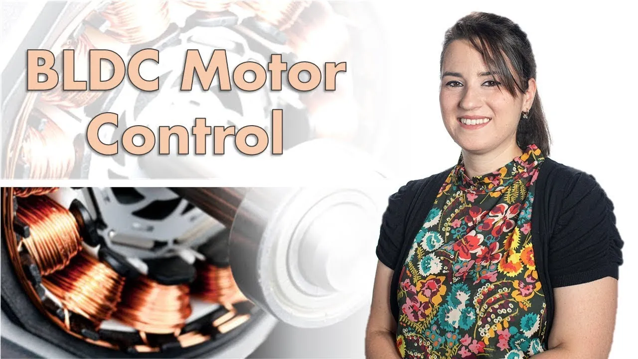
An Electric Speed Controller (ESC) controls a Brushless DC (BLDC) motor by implementing a six-step commutation process where the ESC sequentially connects one phase to the power supply and another to ground, creating a rotating magnetic field that drives the motor's rotor; this process uses MOSFET half-bridges to switch phases and requires current chopping to prevent excessive current draw from the power source.
DIY BLDC Motor Driver ESC Design with Arduino and L6234
Added:Understanding the physical and operational differences between brushed DC motors and Brushless DC (BLDC) motors, including the need for electronic commutation.
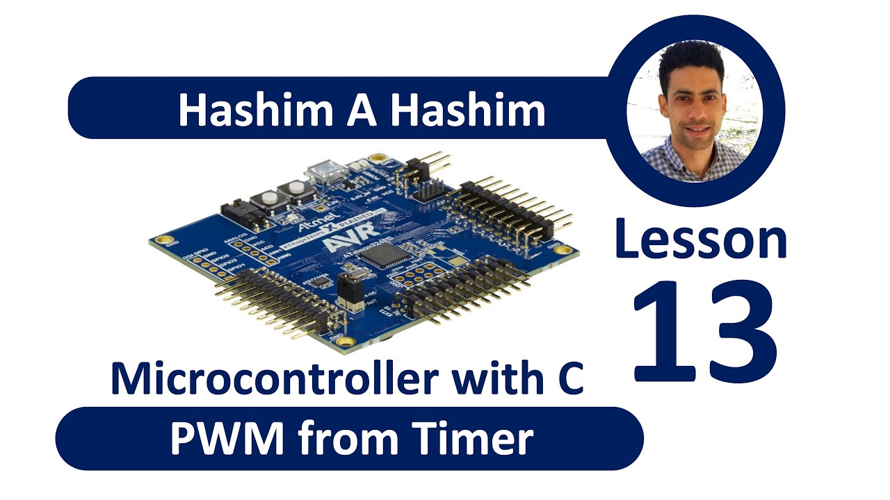
Fundamental knowledge of microcontroller programming (C/C++ in the Arduino IDE), focusing on generating Pulse Width Modulation (PWM) signals and handling interrupts.
Basic electronics theory regarding half-bridge configurations, switching transistors (MOSFETs), and how they are used to control current flow in inductive phases.
Familiarity with 3-phase power concepts and the basic 6-step (trapezoidal) commutation sequence required to spin a BLDC motor.
Exploring Sensorless BLDC control techniques, specifically detecting Back Electromotive Force (BEMF) zero-crossing points to eliminate the need for Hall effect sensors.
Studying Field Oriented Control (FOC) algorithms to achieve smoother torque delivery, reduced acoustic noise, and higher efficiency compared to trapezoidal commutation.
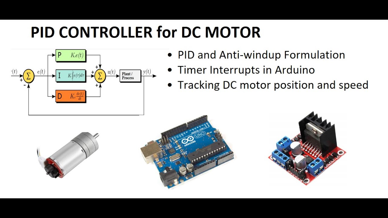
Implementing closed-loop control systems using PID (Proportional-Integral-Derivative) feedback loops to regulate motor speed or shaft position under varying loads.
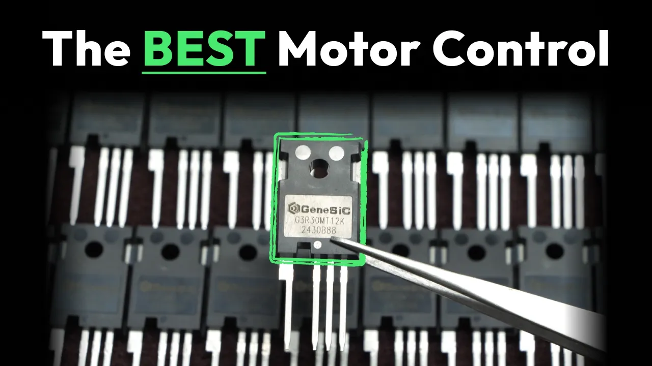
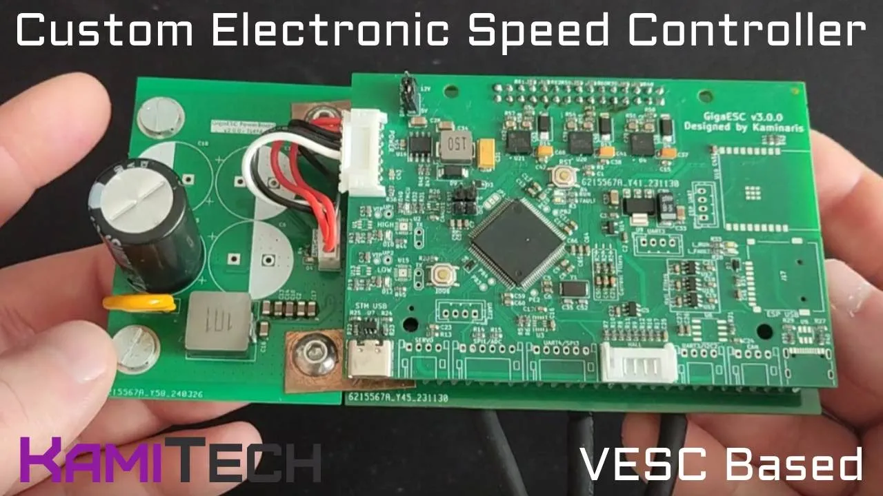
Designing custom, high-power ESC PCBs, including proper gate driver selection, discrete MOSFET selection, thermal management, and noise decoupling for high-current applications.
1.8M views25.3Klikes9:52Original Release: 2017-08-06
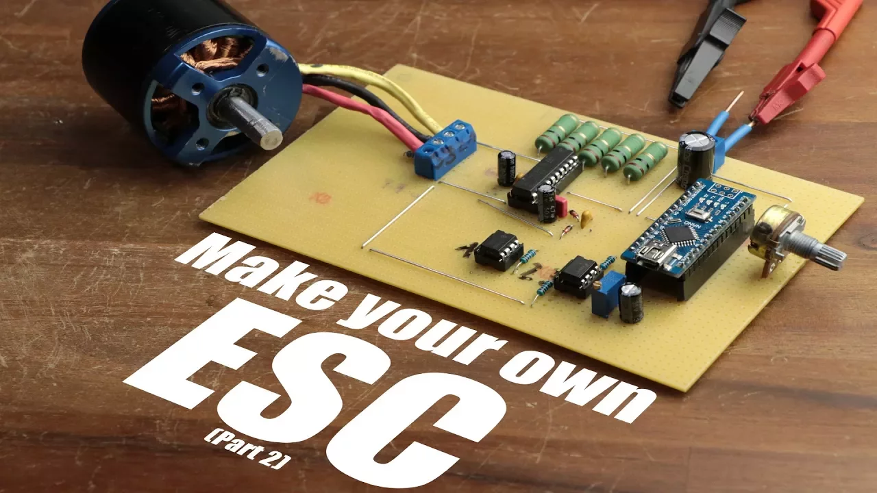
As you can see I am currently working on my DIY quadcopter project which I will probably finish in the year 2022 The heart of the system are those 4 brushless dc motors which through the help of the fitting propellers create the uplift necessary to let the quadcopter levitate I already talked about brushless DC motors aka BLDC motors during a basics video of mine but I missed the chance to talk in detail about so called ESCs or electric speed controllers which directly connect in-between the three phases of the BLDC motors and the power source of the system Simply put their job is to spin the rotor of the motor with an adjustable speed according to an input signal But while that is a rather dumbed down explanation of what they do their hardware construction and control software is everything but simple So in this 2 part video series let’s find out how such an ESC works and let’s try to create our own consisting of an Arduino and a couple of complementary components Let’s get started!
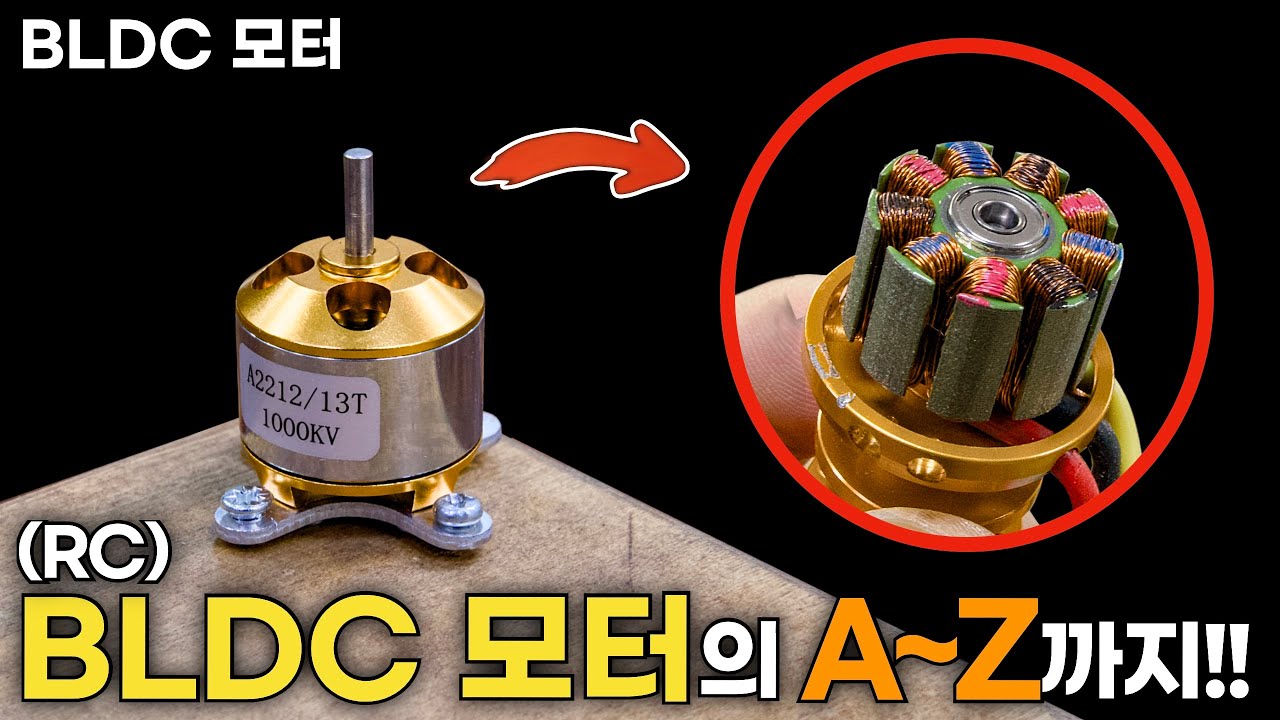
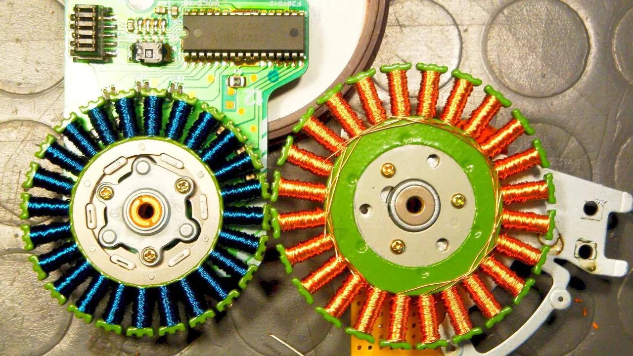
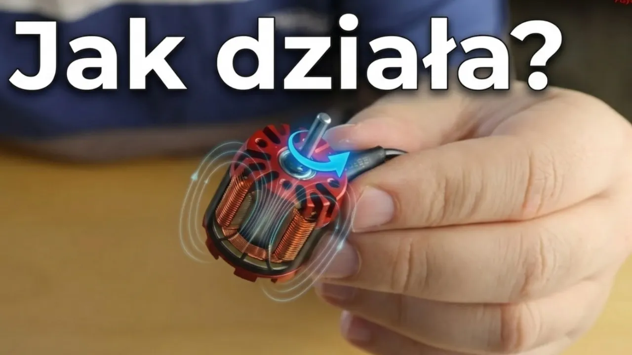
First off, I hooked up three oscilloscope probes to the three phases of the motor and sent an input signal to the ESC so that it rotates relatively slow By the way the input signal consists of a simple PWM signal with a frequency of 20ms and an on time of 1 to 2 ms, while 1ms represents the low speed and 2ms the high speed I created this signal by utilizing the timer1 of the Arduino µC But back to topic, the oscilloscope already shows us that this will not be a simple project but if we think about the overall structure of a BLDC motor we might be able to understand the voltage curves Now a BLDC motor consist of three coils which as we can see are distributed evenly and also tied together in a common neutral point, while their three phases which I will call A, B and C are led out of the motor as three wires This part is called the stator which obviously stays in place while the rotor with its many neodymium magnets surrounds the stator and is like the name suggest the part of the motor that rotates But to keep the explanation easier later on I decreased the number of magnets in my illustration to only 4 Now the voltages we have been looking at so far were the voltages between phase A/B, phase B/C and phase C/A Those are called mesh voltages and usually a bit harder to grasp since they include two coil simultaneously It would be easier for us if we could see the voltage across each individual coil which means we have to use the neutral point as a reference voltage but as I said earlier only the three phases are led out of the motor, not the neutral point So, to solve this problem we could add a 10kohm resistor to each phase and solder them together on the other side to create a virtual neutral point Now by checking the voltages while the motor rotates reveals still complicated looking voltage curves, but let’s have a closer look at them step by step First off Phase A Is pulled up to the supply voltage while Phase C is pulled down to GND After pulsing this behavior for a couple of times which I will talk about in detail later we can see that there is a phase change which means that now Phase B is pulled to the supply voltage while Phase C stays low This phase change process then repeated 4 times, each time with different a phase pulled to the supply voltage and GND before the cycle started over again So, what the ESC basically does is going through 6 steps in which one of the three phases is connected to the supply voltage and one to GND That means that in each step current flows through two coils, each time with a different direction which thus creates a changing magnetic field which attracts the magnets of the rotor and therefore creates a complete 360 degrees rotation of the magnets in those six steps But if you have more magnets like we do it will take a multiple of the six steps but they will still stay the same, they will only repeat themselves a couple of times And of course, if we want to increase the rotation speed of the motor the ESC simply decreases the time for one step and thus increases the frequency of the rotation So now that we know the theory, how does the ESC actually connect the phases to their corresponding voltage potential?
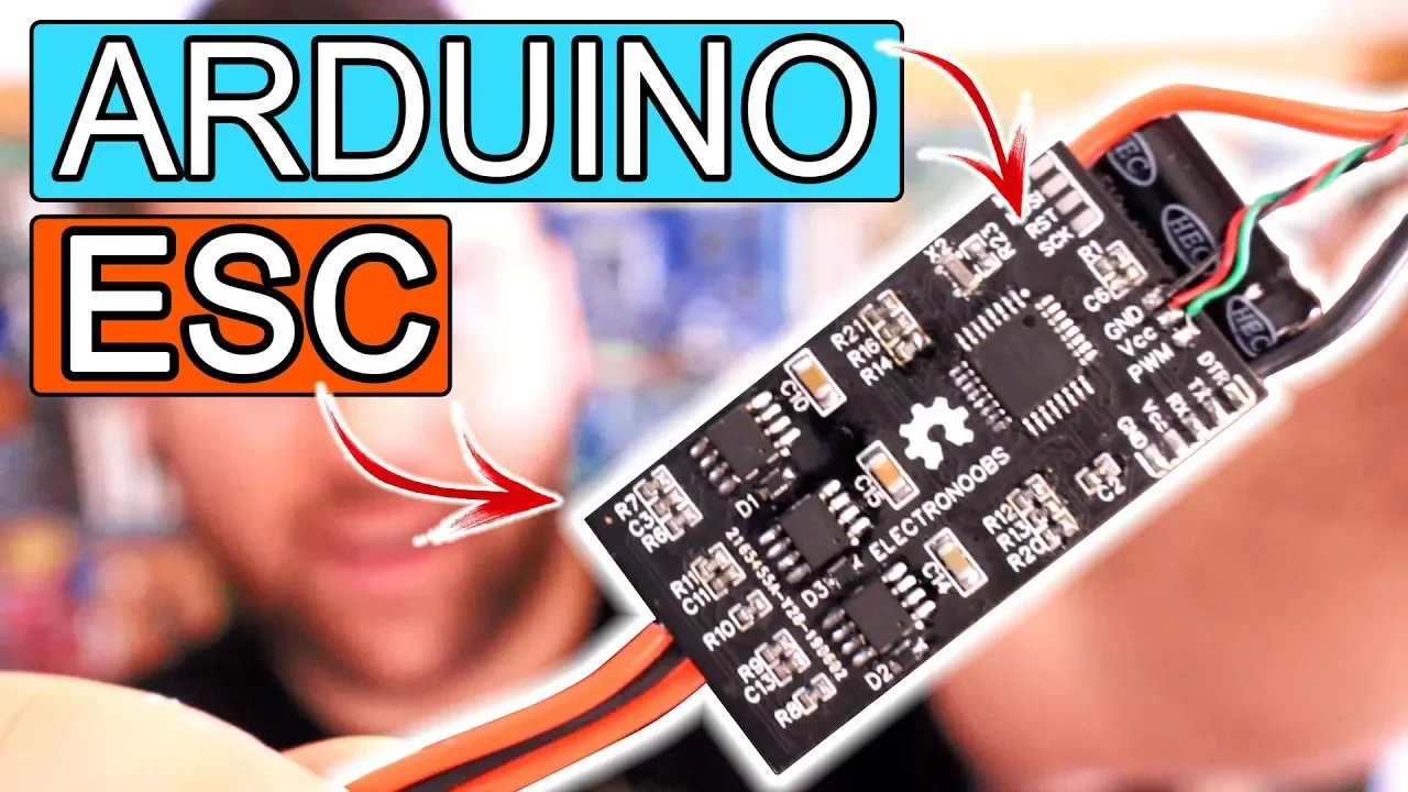
By removing the shrinking tube of one of them we can see the components that handle this job pretty close to the output of the ESC According to their datasheet they are N channel MOSFETs which are connected to the three phases as three half bridges This way we can activate a high side one to connect one phase to the supply voltage and activate a low side one to connect one phase to GND and thus create the 6 different states for the six steps But because we want to use N channel MOSFETs for high side switching we would need a bootstrap configuration to do so That is why I went with this L6234 three phase motor driver IC since it combines the three MOSFET half bridges and driver circuitry in a simple to use package All we need to do is to connect the motor phases to the output pins of the IC and connect its six inputs pins to the Arduino So, I went ahead and created a first schematic for the project in which I not only connected the output and input pins of the IC but also added the complementary components for the bootstrapping, a potentiometer to adjust the rotation speed and 5 1ohm power resistors which will have an important function for the circuit later on Now because creating this circuit on a breadboard could turn out to be quite a hassle due to the high current flow I rather created the circuit on a piece of perfboard right from the start And of course you can find more information about this project like all the schematics, the Arduino code and pictures of my layout design as always in the video description After 2 hours of soldering the first test circuit was complete and it was finally time to program the Arduino As you can see I started off by creating 6 functions for the 6 steps in which I utilized the PORTB and PORTD register to pull the outputs of the Arduino connected the L6234 IC High or Low It may look complicated but once you know that PORTD basically represents digital pin 0 to 7, PORTB represents pin 8 to 13 and a 1 means pull the output high and 0 means pull the output low it is easy to understand And the input logic of the IC is also well described in the datasheet, if the enable pin is pulled high, a low input activates the low side MOSFET while a high input activates the high side MOSFET And if the enable pin is low both MOSFETs are turned off So, after completing the step functions I configured the timer 1 of the Arduino so that it creates a timer compare interrupt in a time interval between 80 and 1.6ms according to the position of the potentiometer The point of this interrupt is to increase a counter variable called step which I used in the main loop to switch between the different step functions And of course, if the step counter reaches the value 6 it starts over at 0 and additionally I also added a doonce flag so that the output registers do not get rewritten continuously After uploading the code, hooking up the three phases of the motor and supplying a voltage of 12V to the circuit we can see that the motor tries to move but it seems like its stuck A first clue to why this is happening can be seen when we have a look at my power supply which reaches its current limit of 3A every half second And if monitor the supply voltage with an oscilloscope we can see how the voltage collapses down to 4V which forces the Arduino to restart But thankfully though the problem we are facing here is easy to understand At first The Arduino activates step 1 which lets current flow from Phase A to Phase C As you might know coils have a very low resistance but on the other hand a relatively big inductance That means that the current through the coils will rise very fast and easily reaches our 3A current limit even within the shortest step duration that we set earlier So, what we have to do is to somehow cut off the current rise at a threshold value so that the current can decrease and then once again rise after a set wait time And to find out how to implement this current chopping feature and how to improve our DIY ESC even more make sure to watch part 2 of this project series Until then don’t forget to like, share and subscribe Stay creative and I will see you next time
Up Next
6:12
Arduino ESC Control: Complete PWM Tutorial for Brushless Motors
@KyleFieldus
111.6K views•2013-10-27

12:54
Triumph of Orthodoxy Icon: Byzantine Art & History Explained
@BenCallan
2.1K views•2024-08-06
7:49
Electronics Waterproofing: Materials and Heat Transfer Analysis
@greatscottlab
1.8M views•2017-12-23

1:42
Game of Thrones Opening Credits: A Cinematic Analysis
@gameofthrones
46.3M views•2011-04-18
Related Study Plans & Knowledge Roadmaps
Structured learning paths in General & Interdisciplinary Studies
general-studies
Elevator Engineering: History, Physics & Cities
01From Hoists to Safety Brakes: The Dawn of Vertical Lift
02Hydraulic vs. Traction: The Engineering Physics of Elevators
03Modern Speed, Safety, and Algorithms
+ 2 more learning modules
12h5 modules
Explore Roadmap
general-studies
Rubber: Material Science, History & Geopolitics
01Origins of Natural Rubber & Mesoamerican History
02The Chemistry of Natural Rubber & Vulcanization
03The Geopolitics of the Rubber Boom & Colonization
+ 2 more learning modules
12h5 modules
Explore Roadmap
general-studies
Containerization: Evolution, Logistics & Trade
01Ancient Trade & Bulk Cargo: Amphorae to Barrels
02The Industrial Revolution & Cardboard Packaging
03The Containerization Revolution: Malcom McLean
+ 2 more learning modules
12h5 modules
Explore Roadmap
general-studies
Textile Tech: Evolution, Labor & Global Impact
01Pre-Industrial Textiles: Handloom & Cottage Industry
02Mechanization: The Spinning Jenny to the Power Loom
03The Factory System & Global Labor Transformation
+ 2 more learning modules
10h5 modules
Explore Roadmap