![[전기기초 1편] 반드시 알아야 하는 전기기초이론 - 전기기능사, 전기산업기사, 전기기사](https://i.ytimg.com/vi_webp/LaZabdwbvBY/maxresdefault.webp)
























A photoresistor is a semiconductor device whose electrical resistance decreases as light intensity increases, due to photons generating electron-hole pairs that enable conduction; to measure this resistance change with Arduino, connect the photoresistor in series with a fixed resistor (5kΩ) between 5V and ground, then read the voltage at the junction using an analog pin, where higher light levels produce higher voltage readings (around 700) and lower light levels produce lower readings (around 200), allowing the Arduino to control LEDs based on detected light conditions.
Arduino Photoresistor Tutorial: Build a Light-Sensitive LED Circuit
Added:Basic understanding of Ohm's Law (V = IR) and how electrical resistance affects current flow in a circuit.
Familiarity with the Arduino microcontroller platform, including how to upload code using the Arduino IDE.
Fundamental C/C++ programming concepts used in Arduino, specifically 'setup()', 'loop()', variables, and basic conditional 'if-else' statements.
The concept of a voltage divider circuit, which is essential for reading analog sensor values like those from a photoresistor.
Basic breadboarding techniques, including how to connect LEDs with current-limiting resistors.
Implementing software hysteresis and calibration techniques to prevent LED flickering at threshold light levels.
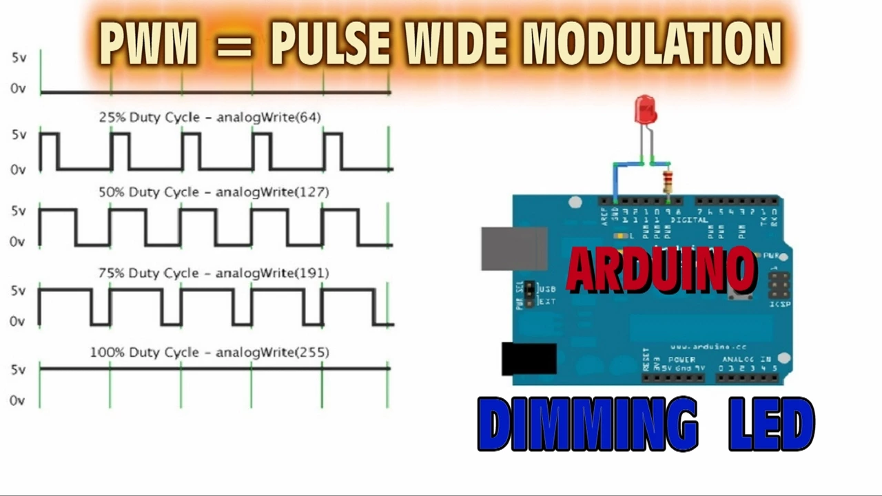
Using Pulse-Width Modulation (PWM) to dynamically dim or brighten the LED based on ambient light intensity rather than just turning it on or off.
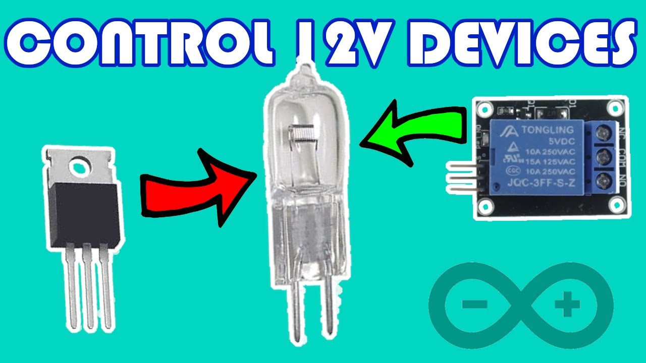
Integrating relays to control high-voltage AC appliances (like household lamps) based on the light levels detected by the Arduino.
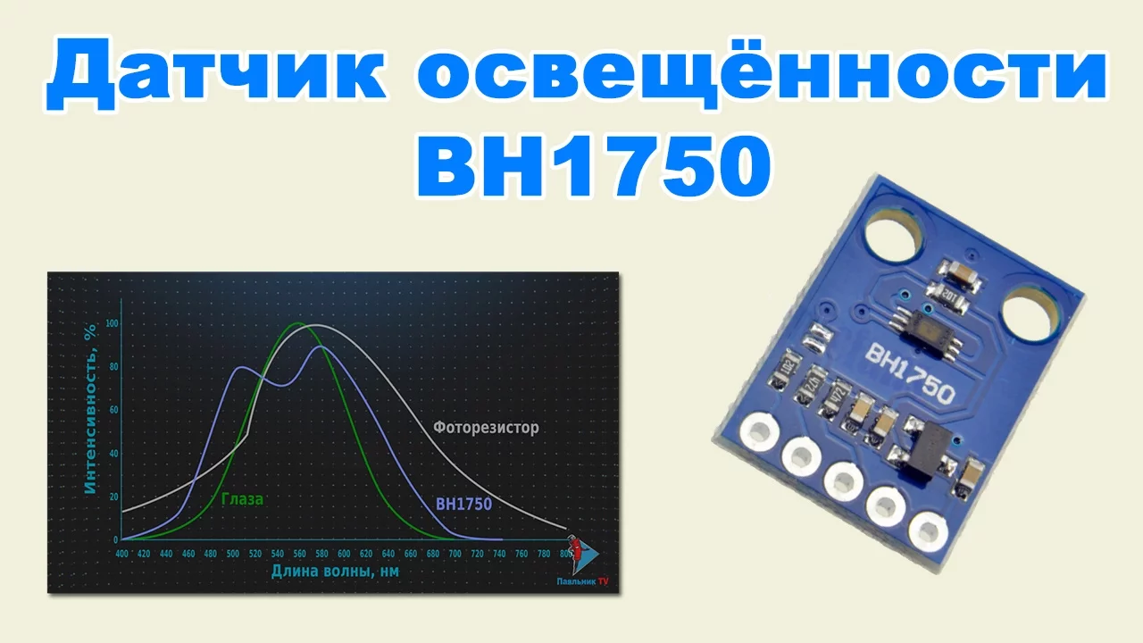
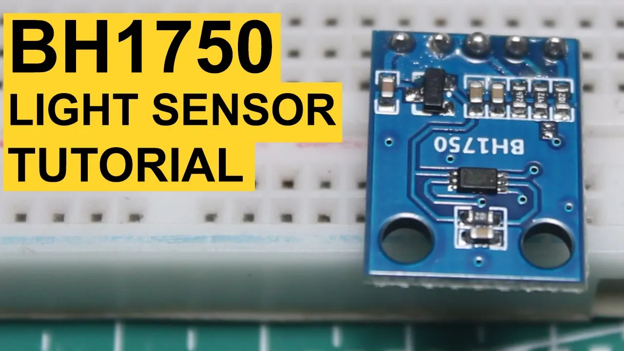
Exploring more precise, digital light sensors such as the BH1750 or TSL2561 for accurate Lux measurements via I2C protocol.
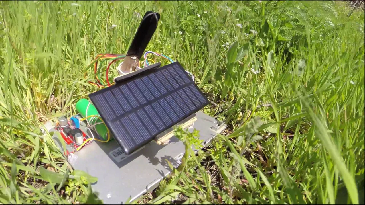
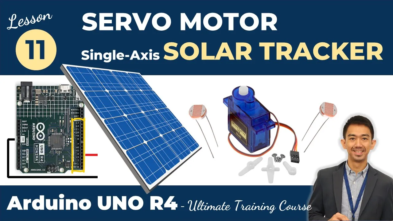
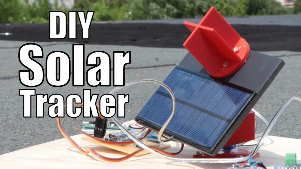
Building an automated solar tracker or smart home automated window blinds system using servo motors and multiple photoresistors.
227.9K views7Klikes36:19Original Release: 2019-08-27
hello guys this is polemic order from top tech boy comm and we are here today with lesson number 25 in our new or improved Arduino tutorial series and what we're gonna do today is we are going to learn how photo resistors are photo detectors work and then we're going to learn how to hook them up and use them in an Arduino project so I need you to pour yourself a nice big mug of iced coffee don't put sugar in it and especially don't put those little sweetener packets in it it is delicious just the way it is also need you to get out your a Lego super starter kit if you haven't picked one up yet go down to the description click on the link hook a brother up $35 it's got an Arduino and a boatload of components which we are using in this in this video series you know and one of the nice things about getting this is that we're working with the same hardware so life is just a lot easier for you and it's a lot easier for me if we are working with the same hardware all right this is what you are going to need on today's project you are going to need your Arduino you are going to need two 330 ohm resistors look at this special day you're gonna get to use a green LED normally we just use red and yellow green is reserved for special occasion so today will be a special occasion and we will be using a green LED you also in your a Lego kit need to get a 5 K resistor you can see that there are these resistors and it is labeled 5k for 5000 ohms and I'll explain why we need to use that in a minute also in today's project I'm going to be using this matte mass mass tech digital voltmeter really good you can do this project without the voltmeter because you can just look at the readings that I'm getting but if you guys don't have one of these look in the link below get you one because you're really if you're going to be doing projects if you're going to be doing electronics you need to at least have one of these DBM so if you don't have one strongly suggest you go out and figure out a way to get one alright so what we are going to do today is we will be working with the photo detector okay the photo detector it's this little thing let me see if I can give you a better look see if it will focus on it hopefully no it just wants to focus on me okay there I think you can see it this little guy has two leaves all right what does a photo detector do well it's resistance changes when the light changes so as the level of light changes the resistance changes and then we will set up a circuit which will allow us on the Arduino to measure that change in resistance and know that that's due to a change in light but I am going to tell you how these things work and I am getting a lot of hate from some of you guys on these lessons where I'm trying to explain how things work or trying to do some math and I think what you want me to do is a lot of you just want me to post my code and then you copy my code and hit download and everything works but you know someone at the end of the day needs to understand how these things work okay this is how a photo detector works a photo detector is so this is a photo resistor we'll call it okay as the light intensity goes up the resistance of the material goes down so if we measure resistance as the light level increases the resistance goes down why it is a semiconductor device and it is pretty close to being an intrinsic semiconductor device go back and look at what I think was lesson number two and we talked about how diodes worked by drawing band diagrams got a lot of heat on that one you're going to get more band diagrams today I'm sorry if we look at energy across the semiconductor so just imagine that this is some two mention X along the length of the photoresistor we have what happens if if you have atoms those atoms have very discreet energy levels that the electrons can be in but if you bring the atoms together to form a crystal if you form a crystal then the atoms start coming together in those discrete energy levels start interfering with each other and then they will smear out and make bands of allowed energy levels this is called the conduction band and this is called the valence band you can have electrons in here you can have electrons in here but you cannot have them in this gap this gap is the forbidden region if you have an intrinsic semiconductor the valence band is full of electrons and the conduction band is empty why is that well because marbles roll downhill if you put a marble in the bowl it's going to want to go to the lowest energy level if you put electrons in a semiconductor they want to go to the lowest energy and here there's going to be almost no conduction why is there no conduction down here with all these electrons imagine you have a jar and imagine the jar is full of marbles and you shake it the marbles don't move because it's full now have an empty jar shake it no conduction no marbles move because there are no marbles so when you look at this in this state this intrinsic semiconductor is going to have a resistance that is very high why is the resistance high because there's almost no ability to conduct but what happens if we send in a photon or light that photon will kick an electron into the conduction band or multiple electrons because you have multiple you have multiple photons coming in and then there are going to be multiple electrons that are kicked up to this higher conduction band this higher energy conduction band well when the electron is kicked up here as the photons come in what happens I have an electron in this empty jar he's free to conduct electricity what do I have I have missing electrons in the jar that's full now the other ones can move around so what happens I generate electron hole pairs from from the photons and what happens to the resistance the resistance goes down and so what happens is the more photons that you bring in the more electron hole pairs you generate and thus the more conduction that you can have the resistance goes down okay that's how this thing works now let's look practically at how it works if I can find it did I lose it no here it is okay so now let's see practically how it works and also we start getting a little bit more practically into the project because in order to hook this thing into a circuit and design a circuit around it in order to design a circuit around it we really need to kind of know what its resistance values are and so I need to get a fresh piece of paper input here and now what I am going to do is I have this I might need to get out of your way a little bit more okay I have this voltmeter and it is set to the ohms reading and I'm going to read the resistance across this device here by hooking up my leads and putting it where you can see it this time all right so do you see how in these photo detectors like this these photo resistors that they don't have a polarity either way either way is okay all right and so let's look at this and I'm trying to point it right at the light so it max brightness you know is it's really right looking at the light the reading of the resistance is one point let's call it 1.5 kilohms so it's 1.5 kilo ohms 1.5 kilo ohms when the light is all the way bright so that's one point five and I know it changes a little bit okay but that is roughly what it is in full brightness now we have to darken the room and so I will turn my studio lights off okay now what do we expect right all that light coming in all that light coming in with generating electron hole pairs that means that it's very conductive that means that the resistance is low so what do we expect when we turn the lights off we expect the resistance to come up and even turning off the studio lights we can see that the resistance increased a little bit but now let's really go dark and as we really go dark you can't read it because this is in the dark maybe you almost can but you can see that it went up to 16 kilomitres don't turn the studio lights on so that we can kind of flip the lights as we need them so what happens when we turn the lights off we're not generating electron hole pairs we don't have conduction so when the light goes off the resistance goes up it makes sense it makes intuitive sense if we're thinking about those band diagrams all right now we need to start thinking about a circuit because we want the Arduino to be able to know are the lights on or are the lights off and so what you can think of and guys this is really important because a lot of the components that you are going to be dealing with a lot of the components the sensors the way they work is that whatever you're interested in the resistance changes is that parameter changes and so you can think of them as a variable resistor so as the light changes the resistance value changes there's also temperature sensors that work that way that is the temperature changes the resistance changes there's all types of sensors whose output is a change in resistance so how do we detect a change in resistance on the Arduino well the first thing that you might think is just take a pin on the Arduino and hook the sensor across it and then as the resistance changes the current is going to change true but what's the problem you can't measure current in the Arduino you can only measure what voltage so in order to use one of these things what you need to do is you need to connect it to the 5 volt pin but you've got to put it in series with this is your sensor this is our light sensor you have to put it in series with another resistor a fixed resistor and let's say I picked the 5k resistor deliberately because if you remember our values were between 1 and 1/2 and 16 K you want the fixed resistor that you choose to be roughly in the range of what the variable resistor or the sensor is going to be and so this is going to be 5 K all right so what is the current the current is going to be equal to the voltage divided by the resistance and what is the resistance it's our sensor plus 5 K all right so as the light goes up as the light goes up the resistance of this resistor is going to go down and as this goes down the current is going to go up as the light is turned off as the light is turned off this resistance becomes larger and as the resistance becomes larger the current goes down alright so then that is also if we think a voltage is going to be current 5 over R s plus 5 K times what times this 5k resistor right so I can measure the voltage right there so what that saying is is that this voltage is going to change as the resistance changes and the resistance is going to change with the light so what that means is if we put this 5k resistor in series with this sensor this voltage at this point is going to change so what does that mean from the Arduino well we don't have to use a control pin what we just have to do is hook it to the 5 volts we have to come across the sensor then we need to go through the 5 K resistor and then we need to come out here and go to an analog pin and then on this analog pin we can write a voltage and that voltage will be very strongly related to what the current is all right so this is what we are going to do and I will kind of do this along with you all right so let's start by hooking up our circuit with the let's let me zoom in a little bit and let's hook up our circuit with the Arduino all right so I'm going to come in and where do I really need to get started I need to get started with the photo detectors which I apparently have lost which I have oh here that's ok that almost panic there because I could not find the photo detector so if we looked at the circuit the first thing we want to do is go across the photo detector so I'm going to put the photo detector or photo resistor between column fit between column 10 and column 15 and remember the direction doesn't matter and then I'm going to come in and I've got to make sure I use the right resistor the five K resistor and not the current limiting resistors for the LEDs I believe these two are the same and this is the five K resistor I really need to teach you how to read resistors from those little rings one of these days I'm going to go the one leg of the resistor is going to connect to the bottom leg of the photo detector so I'm going to go from fifth column 15 to column 20 see see there's a connection between those two now remember this whole thing is going to connect to I will use the red wire the whole thing is going to connect to all right let's look here I've got the left leg of the photo detector is going to go to 5 volts it will go to 5 volts like that now the bottom leg of the resistor remember that is going to go to ground I'm going to use a black wire for that so that is going to go to GND now it is this Center it is this Center what is that okay it is this Center connection between the photo resistor and the in the normal resistor the fixed resistor that we want to measure and so I will grab a wire into that column and then I'm going to bring that over to a zero all right so now this is all hooked up and so what we need to do now is we need to read the value off of a zero and what we should see is we should see that that changes as the light changes so we should read a number it's not going to become it'll be between zero and ten twenty three but it won't go over that full range but it should be numbers between zero and ten twenty three and then we need to record the values that are indicated when the light is off and then record the values that are indicated when the light is on so I need to come over here and open up a fresh IDE okay let me get this and I know I need to switch over where you guys can see it alright so let me get this over here and see if I can get a good view here perhaps this will be a that is a pretty good view don't you think you can see everything that is going on and so let's come up here and this is going to be pretty easy code because we've got a fixed five volts across the photoresistor and other resistor we don't have anything to do there we just have a pin which is going to be a zero so we are going to call that light pin because we're reading the light there and that is going to be equal to a zero I believe and then we're going to need int we're going to need light Val that is what we're going to read off of that pin and so we don't need to put a value in there we will need to do a pen mode we will need to do a pin mode so we're gonna do pen mode we are going to do light 10 is a watt it's an it's an input we're reading from it input like that all right now down in the void loop what do we want to do it it is pretty simple it is going to be pretty simple what we are going to do is we are going to read from that pin so what do we do light val is going to be equal to analog read of what of light pin and so we're just going to analog read and then builds 2 up let's turn on our serial monitor up here because we want to prints we do it a serial dot begin and we'll do the trusty 9600 oops I hit some strange key there okay now six-hundred like that okay I'm hitting the wrong keys 9600 so now light valve we bred so we're gonna print it now serial dot print Ln and what are we going to print we are going to print we are going to print light Val because we are reading that and then I want to put a delay of I'll put delay value and then I will come up here and be a good person in these variables yet delay value is equal to 250 milliseconds all right so this should just sit and it should read and it should print and I'm gonna try to move to a view where hopefully you can see this but let's go ahead and download this hold your breath oh it's gonna work okay so now let's turn on the serial monitor and let me see if I can get a window where you can see the serial monitor look at that alright so we are reading a number between 0 and 10 23 now let's remember what we think is going to happen as we change the light okay as I turn the light off the resistance going to be higher as the resistance gets higher the current gets lower and as the current gets lower the voltage is going to drop okay the voltage is going to drop so as I go in let me say that again as I turn the light off the resistance of the photo detector will go up as the resistance of the photo detector goes up the current will go down when the current goes down then the voltage across that 5k resistor will go down so what do we are the voltage of that across that 5k resistor will go down so what do we expect to happen when I turn the lights off to this number we expect to go down by probably a factor of two boom it went down even more than that do you see that it went down to 200 about 200 now it's up to 700 why does it go up the lights are coming in it's generating electron hole pairs in this photo detector the electron hole pairs make it more conductive when it becomes more conductive the resistance goes down when the resistance goes down I get more current more current leads to more voltage across that boom okay now what your assignment is your assignment is to hook up a circuit which will turn the if the lights are on in the room you want the green LED everything is okay green the lights are on but if the lights go out you want to turn on the red LED okay you want to turn on the red LED now you to make this work you're gonna have to look at what these values are like what we saw in this room that when the lights were on it was around 200 okay it was around 200 and when the lights I mean when the lights were off it was around 200 and when the lights were on it was around 700 okay so what I want you to do is I want you to set up a circuit and I want the red LED to come on if the lights turn off in the room and I want the green LED to turn on when the lights are on you go do that by yourself you figure it out and then when you come back I'll do it with you but do it yourself get it working and then when you come back see if you did it the same way I did it okay let's see what I am going to do I'm gonna first switch over here to this view so you can see me hook this up you ought to really be adept at this point at hooking up LEDs so I'm gonna go pretty quickly I'm going to put my red LED in column 25 the law or I guess I'm gonna start with my current limiting resistor current limiting resistor is going to go from column 25 to column 30 alright and then the long leg of the LED needs to point back towards the voltage source so I'm going to put it in column 30 and then the short leg of the LED is just going to be over a couple of columns now to hook that up what I'm going to do is I'm going to bring column 25 to pin 9 okay so one of the pins that I will be using to make this thing work will be pin 9 now I'm going to repeat that for the green LED but I'm gonna go from column 35 to column 40 from column 35 to column 40 then long leg of the LED connects to the resistor short leg a couple of columns over then I'm going to connect that to that resistor to power it over to pin 8 okay it's connected to pin 8 and now I need a couple of ground wires right I need a couple of ground wires so the lower leg the short leg of the green LED is going to go to and I am running out of ground wires but I think I can still do it I'm gonna go to the ground that's over there beside pin 13 ok the ground beside pin 13 for the green LED the ground beside pin 13 and now I still need to ground the short leg I need to ground the short leg of the resistor I mean the short leg of the LED guys if you are not following this go back and look it I think lesson number 3 where we showed you how a breadboard is but we're a breadboard works but I'm getting to the point I mean I've got to do this stuff faster I can't every time go real slow to show you how to hook up an LED you should know how to hook up an LED by now and so there is another ground pin here by five volts which I'm going to connect to so I've got the 5 volt going to the top of the photo detector I have a ground coming from the resistor that's in series with the photo detector then I'm supplying power to the current limiting resistor of the red led by pin 9 in the green LED by pen 8 so if you guys have been following along you ought to be able to do this with me as I do it quickly and if you haven't you just need to go back and look at some of those earlier some of those earlier lessons all right let's get some coding done here and let's see what was that most excellent view where you could see me and the serial monitor and everything I think this I think this was it let's see if I can make this any okay so now we are going to come up and we can probably use a couple of these values we still have white pen we still have what light bell we still have this so those are pretty good I need int I need red pin and the red pin was ten nine equal nine all right and then I need int and I need green pin and that was an eight so that's going to be equal to eight and now I need to do a couple of more pin modes here I need to do n mode and I need to do red pin is going to be an output and then I need to do a pin mode three green pen and it needs to be an out output all right so my pins are set up now I'm still reading lot values so that's good now what did we say we said the trick is to kind of figure out where you were going to set your values and it seemed like when the lights were out we were at about 200 okay and then when the lights are on we were at about 700 all right let's see yeah you see this little wire had gone over the photo sensor and it kind of cast a shadow on it and the value went down okay so what we need to do is we need to do some if statements and this is what I want you to think don't say if it's equal to 700 or if it's equal to 200 because it's kind of there's variations and there's in between values so how do you want to do it well if you have like lights lights on at 700 and then lights off are about 200 how would you want to do this what I think I would do is I would say if and then what am I looking at like Val okay if white val is greater if light val is greater than 350 what do I know I know and then I'm going to open my clause and then Arduino adds the close what do I know in that case well in that case I know the lights are on if the lights are on everything is good so I should do a digital right and then I should do green pin should be what hi all right now what you would probably think is okay now I'm gonna go do if light val is is less than 350 then I'm gonna say red pen aside that's right but you've got to remember you've got to undo what you did and so if you come in here you've got to also remember what's the other thing you want to do you want to turn the red pen what off because if you didn't do that then they're both gonna stay on so you got to remember to kind of clean up all right now what's the other one if light Val light Val is what less than 350 if flat Val is less than 350 open the clause now what do we want to do we want to do the opposite so I'm going to just copy these controls see that that was I hope I have an undo I don't know what I did there okay let me get those in control C and then come down here control V now this time we want green tend to beat what low and we want red pin to be cut so what we want this to do is we want this to warn us if the lights have gone off let me let me download this and see ah okay lights are on we're good to go right lights are on we are good to go and in fact let me let me just leave it like that and I will come over here and I am going to turn off the lights and nothing happened we have an error houston we have a problem so let's see 200 the values that we're reading 200 is less than 350 so if I say yes and light panel take red pin high I might have a problem how I this up so let's see that's grounded the orange comes to the end we make sure I did pen 9 can you guys see what I did wrong red pen is pen 9 comes over to my resistor long leg of the resistor it is there I do come back to ground ok so guys this I don't a lot of times I make mistakes on purpose but did not make a mistake on purpose here and so I want you to see that this is not working and so what I want to see is is my basic LED circuit working so I've got the current limiting resistor on the red LED hooked to the red LED I'm going to take this wire that is on that circuit and instead of 10 9 I'm going to hook it to 5 volts and when I do that it comes on that tells me this circuit is working so now I need to come back to pin 9 and put it in and I need to figure out why it is not working ah there it is okay so probably what had happened why was that not working man this is great when things go wrong like that probably I just had a loose connection and it wasn't it wasn't working because of that all right so let's play around with this let's play around with this lights are on I actually think you can see this better when we were in this view down here like this I actually think the LED shows up better maybe not let's try this one okay you can clearly see that the green light is on all right now we're gonna turn the lights off and the red light comes on green red okay guys let's review what is happening let's review what is happening when you have light you generate electron-hole pairs it becomes more conductive which means the resistance drops when the resistance drops you get more current which leads to a you could get more current which leads to a larger voltage a larger voltage across that series resistor when you turn the lights off the resistance goes up when the resistance goes up you have less current when you have less current you have less voltage across that resistor that fixed resistor that you are that you are hooked up to okay guys we went all the way from solid-state physics to hooking up a circuit based on a little circuit design based on and then hooked hooked up the Arduino encoded and make things work and this is how you work if you're a real engineer man this is how you work if you're a real engineer you got to start with physics you got to do a little math you got to do a little circuit you got to do a little engineering you got to do a little coding and then you hook things up and you make it work I feel like I'm getting a lot of hate on these where I actually go in to try to help you understand how things work but at the end of the day someone has to know how these things work right you can't just sit and copy and paste people's code the rest of your life you need to learn a little bit of the physics you need to learn a little bit of the math all right this is palma quarter from top tech boy comm hope you hopefully you guys will give me a thumbs up hopefully you'll subscribe and share this and I will talk to you guys later
Up Next
2:16
Stepper vs Servo Motors: Accuracy, Control & Cost Guide
@ATOcom-Automation
147.5K views•2024-03-31

30:32
Ultrasonic Transducers: Resonant Frequency Measurement and Horn Design
@imajeenyus42
229.9K views•2017-02-22

70:35
Arduino IMU PID Control System Design and Tuning
@paulmcwhorter
67K views•2020-02-06

33:39
How a Student's Question Saved a NYC Skyscraper from Collapse
@veritasium
22.8M views•2025-04-26
Related Study Plans & Knowledge Roadmaps
Structured learning paths in Engineering
engineering
Building Acoustic Levitators: Physics & Arduino
01The Physics of Sound and Standing Waves
02Piezoelectric Transducers and H-Bridge Drivers
03Arduino Programming: Generating 40 kHz Signals
+ 2 more learning modules
14h5 modules
Explore Roadmap
engineering
Building Peltier Cloud Chambers: Particle Tracks
01Cosmic Rays & Cloud Chamber Physics
02Thermoelectric Cooling (TEC) Fundamentals
03Custom Liquid-Cooling Loop Design
+ 2 more learning modules
18h5 modules
Explore Roadmap
engineering
Yagi-Uda Antennas: Modeling, Build & VNA Test
01Introduction to RF and Antenna Fundamentals
02Yagi-Uda Antenna Design Principles
03Antenna Modeling and Simulation in 4NEC2
+ 2 more learning modules
18h5 modules
Explore Roadmap
engineering
ECG Monitor Design: Op-Amps, Filters & Noise
01Electronics & Breadboard Basics
02Op-Amps and Instrumentation Amplifiers
03Bioelectricity and ECG Fundamentals
+ 2 more learning modules
18h5 modules
Explore Roadmap