













![Hector SLAM Using Hokuyo LIDAR and Mobile Robot With ROS(Robot Operating System)[MELODIC]](https://i.ytimg.com/vi/lXU4CurkpuM/maxresdefault.jpg)


![[ROS2] 5-2. AMCL 패키지 설정법|R2R 심화|민형기 강사님 무료 강의](https://i.ytimg.com/vi/nRCa3UUXrUg/maxresdefault.jpg)
![[ROS2] 5-1. AMCL 패키지 구경하기 - Localization|R2R 심화|민형기 강사님 무료 강의](https://i.ytimg.com/vi/Vju8tufEkj0/maxresdefault.jpg)



Coordinate frames are essential reference systems in autonomous vehicles that define the position and orientation of sensors, the robot itself, and the environment, enabling the conversion of sensor data from local frames (like lidar or camera frames) to global frames (like map frames) through rigid body transformations that combine rotation matrices and translation vectors; ROS provides the tf and tf2 packages to manage these transformations, allowing developers to transform points and poses between different coordinate frames using homogeneous transformation matrices.
ROS Coordinate Frames and Transformations for F1tenth | UVA Course
Added:Basic ROS (Robot Operating System) concepts, including nodes, topics, publishers, subscribers, and the workspace environment.
Fundamental linear algebra, specifically 2D/3D coordinate geometry, translation vectors, and rotation representations (rotation matrices, Euler angles, and quaternions).
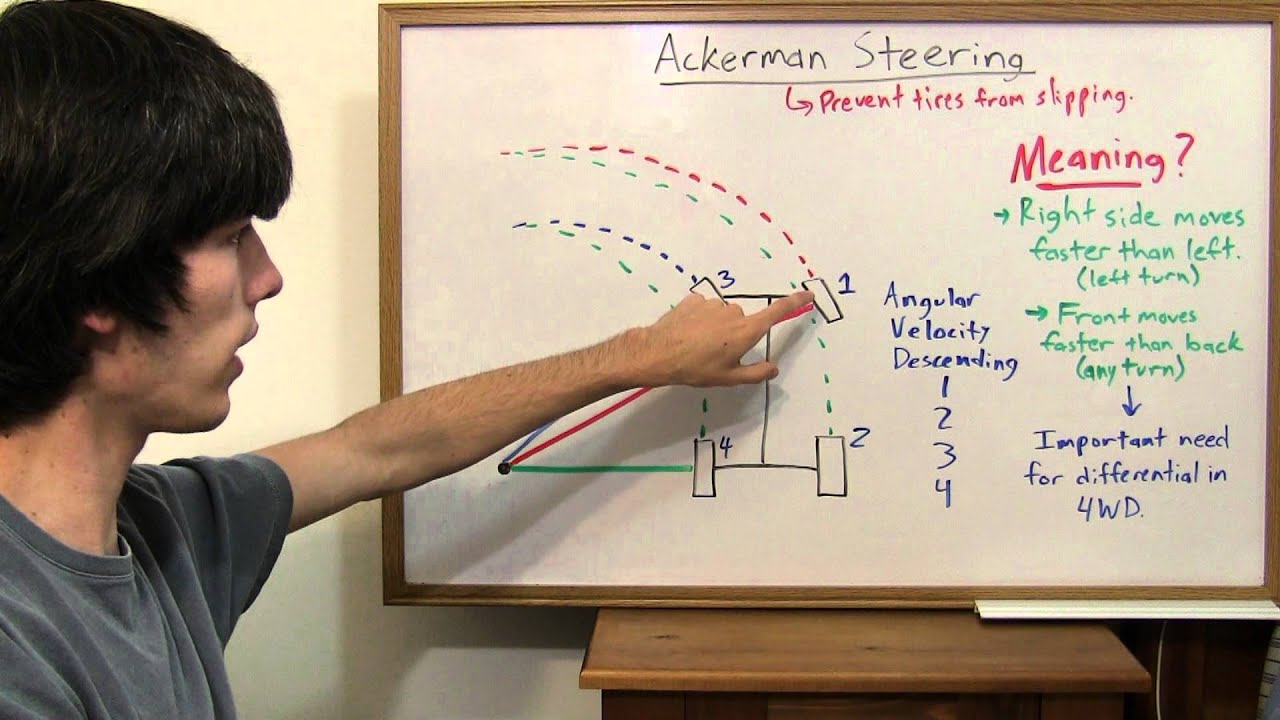
An introductory understanding of mobile robot kinematics, particularly Ackermann steering as used in the F1tenth car, and the basic concept of wheel odometry.
Familiarity with common robotic sensors, such as LiDAR (laser scanners) and Inertial Measurement Units (IMUs), and how they gather spatial data.
Implementing SLAM (Simultaneous Localization and Mapping) algorithms, such as Cartographer or Hector SLAM, to generate track maps using the established coordinate frames.
Configuring AMCL (Adaptive Monte Carlo Localization) or other localization packages to estimate the car's pose relative to the map frame.
Designing and implementing path planning and tracking algorithms, such as Pure Pursuit or Model Predictive Control (MPC), utilizing the TF2 transform tree for spatial references.
Deploying sensor fusion techniques using Extended Kalman Filters (EKF) via the robot_localization ROS package to combine IMU and odometry data.
15.9K views392likes1:15:00Original Release: 2020-03-18
all right so um welcome back to uh f110 autonomous racing um as you have received several announcements uh till they seen me um show you some examples of these uh coordinate frames like the map frame or something called the base link or the laser link or the lidar frame um and so i hope by now you have some intuition for why we need a coordinate system why these frames are important what they represent but we haven't really delved into the details of what are these frames what is the methodology behind naming them what are transformations between one frame and the other so i want to cover that topic uh in the lecture today uh and this also you know will serve as a transition to working and better understanding the simulator because the simulator you will see uh will utilize all of these coordinate frames and transformations that we will cover today so in in addition to that i want to talk a little bit about the tf and the tf2 ros packages which is uh what the implementation of this ros transformation um is is accomplished through these packages and so as as always with everything else i will show you the intuition first then a little bit of math to convince you how this works and what happens underneath the hood and finally we will wrap the lecture today with the overview of what some of the api calls and the package tools are available for us to interact with transformations and again time permitting i will maybe even show a demo of some transformations with turtles okay so so let's jump into the topic of the lecture which is coordinate frames and transformations so to build some intuition about why this is necessary um i want to show you this this image which compares and contrasts what the f-110 car the real hardware has in terms of the sensor capability and the compute capability as compared to you know a typical prototype of a full-scale self-driving car and i should also mention here again that the simulated f-110 car has the same virtual capability as the real car the only difference is that you know on the real car we spent a lot of time in looking at the the vsc which sends the pwm signals to the actual drive motor that part has becomes more simplified in the simulation because we don't really need a vese in the simulation we can directly control the speed and the steering of the of the car itself but that's not the point here the point here is that on all of these 110 scale or full scale autonomous vehicle setups you have a different set of sensors and each sensor is going to report data in its own local frame specific to that sensor right so the lidar will tell you distances from the lidar itself the camera is going to detect obstacles or other features with respect to the coordinate frame which is on the camera the same goes for radar or short range ultrasonic sensors gps what have you and so so this makes it important to to talk and have a common coordinate system to express this data and another reason why you meet you may need frame transformations is that when you map a large area for example let's say a city or a large track you may not actually build the entire map in one shot right so you see here the output of a slam algorithm called cartographer but the map is getting built by stitching together different maps which were built maybe at different times so a large scale mapping is typically accomplished by stitching together these sub maps together which are roughly shown in this uh sort of animation and so in order for us to stitch these two maps or sub bring these sub maps together we need a way for a common frame of reference or a common uh coordinate system to describe the position of obstacles and the boundaries from one map with respect to another map or with respect to the entire world as whole so so not only do we need frames to get the data from the sensors we also need transformation between the frames in order to tie everything together into a global coordinate system or from one coordinate frame uh into another frame so what is this coordinate frame that i keep referring to so this is just a very simple definition shown especially with an example of the f-110 car so shown here is a coordinate frame is simply a set of three orthogonal axes for the x y and z direction and they have a origin where you place this frame so on the on the top right and maybe let me just quickly switch to pointers so on the top right you see an example of a coordinate frame which is placed at the center of this uh f110 car with the lidar in the front and the camera in the front as well on the bottom left you see an example of what you could call or describe as the world frame right so this entire map and anywhere the car is in this map the position of that car would be measured with respect to the origin on this bottom left corner in this map or the world frame and here you see a top-down view of what this exact frame looks like with the x pointing in the front of the car y is pointing towards the left of the car and z is coming out upwards towards you uh from the top of the car right so in many robotic systems uh the first step is always to figure out and assign some coordinate frames to make sense of the position of the robot right so here's an example that illustrates a very trivial but important point so on the left image you have the the car and the corridor uh so we have a race car or a robot r and we want to represent the position of the robot with respect to the coordinate w or the world frame in um in this picture and the origin of the world frame is on the bottom left corner as is depicted and so you can see roughly that the car is located at uh x equals two point something and y is the double of that so four point two so two point one and four point two is somewhere around here but if you have multiple cars or if you have an obstacle in front of the car you could also assign a coordinate frame on top of your red car itself so you have a robot r1 and then you have another robot r2 you could then say what is the position or relative position of r2 with respect to r1 okay so in this image you can see roughly that r2 is located mostly along the x axis so that's why we have x is eight and then in terms of the y direction it's on the negative y or the negative green direction which is why it's like negative zero point one so so this is a very trivial point to show that any position or pose of the robot only makes sense when you have defined the coordinate frame in which you are describing that pose and this is not just true for the position it also holds true for orientations of robots so remember how the pose of a robot is a combination of the position and its orientation or the rotation aspect of the robot as well which is the theta so you have x y z and theta which fully describes where one robot is located either with respect to another robot in which case you are talking about the frame of reference on the robots themselves or they are absolute position and pose with respect to the world frame or the coordinate axis on the bottom left right so this makes talking about the pose of the robot very easy and straightforward and that's why uh you know every robot requires some coordinate frames to describe uh its position so very quickly let me uh describe some conventions that ross in particular uses in general these con you know you'll find these conventions and a lot of literature in robotics itself and the the the key idea here is that the xyz orthogonal axis they follow what is called the right hand coordinate system where your if you point your index middle finger and the thumb uh orthogonal to each other using your right hand then your index points towards the x axis your y the middle finger points towards the y axis and the thumb will point towards the z axis in other words um you know if you uh if you place your right hand in the depicted orientation on any other robot that will give you the convention in terms of the directions of these three axes with respect to each other so the so-called right-hand coordinate system the z-axis points along the thumb of your right hand you could even do this with your left hand and that inverted coordinate system is more prevalent and sometimes used in graphic design more so than in robotics so robotics typically uses the right hand coordinate system and so does ross and while we are looking at this image it also helps to mention that the color convention in robotics and ross in particular is also fixed so rgb red green and blue will always correspond to x y and z axes uh in ros so that's a very easy way to remember the orientation of these three axes even when the labels are missing just by looking at the color right so going back to the the question at hand on why do we need a transformation between different frames a very simple example is that you have a lidar or your camera and that camera or the lidar detects some obstacles in fact this is one of the uh one of the halves of the assignment that will be released where you have to implement automatic emergency braking where the lidar will you know detect some obstacle in terms of distances away from in terms of the range from an obstacle in its own field of view so the question arises if the lidar reports that there is an obstacle a certain distance away from the lidar then what does it tell you about where the obstacle is in terms of the larger map right so or does it even tell you anything about where you are uh within a larger map and and that's really what the what the fundamental challenge is to use transformation and frames that you get data in what you call the sensor frame but you want to import or ingest that data and transform it into another frame maybe the map frame which has a much more global perspective than the perspective of just being on the robot itself so therefore we must link these frames together in some mathematical way and that's where transformations come in so what is an example of this transformation so here's one older version of the f110 car you can see it uses the older nvidia tk1 platform instead of the tx2 and it has a lidar mounted at the rear top of the top plate of the car itself so you can see we have two frames of reference here so we have a frame of reference or a coordinate frame on the lidar itself or at the center of the lidar and convince yourself that this is also following the right hand thumb rule with the z pointing towards the direction of the thumb and x and y being consistent with that but we can also place another uh frame on the robot itself right so maybe in the middle of the robot or on the front axle or on the rear axle and so the data that you will get from the lidar is going to be in the frame of reference of the lidar but you may want to transform that data into the frame of reference of the robot which is often called the base link and we'll study more about that in just a second so in this picture from this front view you can immediately tell that there is a rigid static transformation between the where the coordinate frame of the robot is and where the lidar is denoted by this delta z component right because x the origin is on the z axis in this case and by the way it's your choice where to place this coordinate system although there are some conventions which many packages use and we'll discuss them uh when we get to that point but if we look at the same um sort of view of the car from the side or from the top it looks something like this right so we have the the front coordinate frame of the robot which is the same as this bottom frame on the left image and on the left image we see that the lidar is at a delta z transform away on the z axis but it's also actually a delta x distance behind or away from this frame of reference of the front of the robot right so those the values of the lidar if the lidar detects an obstacle it will not tell us how far the front of the robot is from that obstacle it will only tell us what the distance of the obstacle is from the lidar so you need a static transformation in this case to convert any data and then compute the distance of the obstacle from the front of the car by always using the delta x then the delta z static transforms in this case so we'll discuss in more detail of all the frames of reference or the coordinate frames on the f-110 car but this was just meant to be an intuitive example to show you why you need a coordinate frame and why would you need any sort of a transformation between different coordinate frames all right so continuing with the same example previously we had the lidar frame or the laser frame that you can interchangeably name them uh placed on the top of the lidar then you had another frame which was earlier placed in the front and this new example it's placed on let's say the center of the car or the cg of the car and now we are introducing another frame which is the map frame right so the map frame is again up to you where to place the origin of this frame um and then the point is that as your robot moves you need to track the position and the pose of the robot with respect to something right so you cannot track the position of the robot with respect to the later laser because the laser is moving with the robot itself and the same is true for the car frame so when this robot moves after some time t delta t you see that you get new data in your lidar frame which has also moved with the new position of the lidar then there is a static transformation this orange arrow between the lidar and the base link of the car and then you can track the position of the car by looking at the transform of the car frame with respect to where your map frame was right so you see the map frame hasn't moved from one time to the other time but we are using this original information of where the origin of the map frame was to compute the transform which will give us the pose of the car as it moves uh in the world right so there exists this relationship between different frames some of them are static relationships for example the distance between the lidar and the car frame doesn't change over time but some of them are dynamic relationships where there's transformation of where the base of the car is with respect to the origin of the map is changing over time so here's a small video to show you why we need frames and how the same data looks different from uh based on the perspective of where you are looking the data from so so in this uh video you see uh what the lidar frame of reference reports the data as right so what you are seeing are subsequent lidar stance the car is static or not moving because we are just reporting what the lidar sees at any given time and so you can imagine that this is what you see if you were to visualize the scan data in the lidar or the laser frame because the world just moves around the lidar and the lidar stays at the center of the world but if you use an algorithm to look at this data and build a map of the world and replay the same data in the map frame or the world frame then it would look something like this where the actual actually the robot is moving in this map and the lidar scans which the robot reports are going to be consistent with the previous video so actually in this simple example the robot is just moving across the lab and then eventually it turns as well but you get a new perspective in terms of what the robot is doing by just switching from one frame to the other and all we have done here is going from the laser scan reference frame or coordinate frame in the previous video to the map frame in this new video and so the question is how does this occur how is ross able to compute these transformations what do you have to do in order to utilize these frames on the f110 card so we address all those questions by the end of this lecture okay so so let's talk about the reference frames on the f110 card and we have multiple reference frames like i've said before the reason we have multiple frames are first we need to know the location of where our car is in the world so you know maybe we need a map frame somewhere so that we have an origin or a reference point in terms of describing the absolute pose of the car in the world and then we need some transformation or we need to know what is the relationship between the frame in which you are measuring stuff or you know the measurement frame like the laser uh and the actuation frame maybe like the base link of the car or the the car frame on the front or the rear axle so so we just saw a video example of this phenomena so i just want to make sure everybody is on board with what happens when you go from one frame to the other with the same data so here is a snapshot in time of from a simulator where you see the data being reported by the laser frame right so you can see some information about the width of the track how far the left hand turn is and you you see some information about the relationship between the race car and the world but if you transform the same data into a map frame you can actually see where the car is in this loop or in this map right so they are and in fact the laser observations they match with our view of the environment or the or the map of the environment so we know where the robot is in the environment and and showing this side by side i hope will you know convey this this point across that all what has changed from the left image to the right image is uh the frame of reference in which we are viewing our data so here we are viewing the data in the laser frame of reference and here we are viewing the data and the map frame of reference and they're the exact same data at the exact same time so to summarize why do we need different transformations let me just quickly go over some of these points some of the obvious ones are that the data that we measure is usually always provided in the most convenient frame of the data source right so what that means is it makes sense to report lidar ranges with respect to the frame of reference on the lidar that's the most convenient frame to report lidar data because that's what the range actually means it's the distance away from the lidar similarly you may have images or depth cameras or other sensors like radars the most convenient frame to report the data would be the measurement frame or the sensor frame secondly if we have multiple maps or disconnected maps which are sometimes called sub maps we saw an example earlier in the lecture we want to know the location of the robot in one map with respect to another or within a global sort of a you know a combination of all these sub maps so that's again very useful to do that when we have transforms between different map frames needless to say that if we have some a map frame defined then the dynamic transform between where the car is at any given time is another way of saying that we are localizing ourselves within a map right and then we saw an example of this as well when an obstacle is detected in the sensor or the laser frame on the f-110 car we may want to actually render the obstacle on where it is present in the map so that during the next time in the lap when the car is there it can plan differently because it already knows there's an obstacle here as we were able to transform the obstacle from the laser frame onto the map frame so to go back to the point at at hand the f-110 car both the physical car and the simulated car uses the following four frames okay it uses something called the map frame uh the base link frame and the laser frame and then it also uses an odometry frame and there's a reason why odometry has been shown in parenthesis and i'll explain why this sort of frame is redundant or you know not really reporting the position of the car we mostly use the map frame for that and just a reminder i've stated this point already that the convention in raw says that rgb the color convention always corresponds to the x y z axis using the right hand thumb rule excuse me so let's go over each of these frames one at a time to understand their relevance with respect to the f110 car so as one can imagine the map frame is simply the origin which is set by the user and every other transformation in terms of the odom or the base link can be measured with respect to the map okay so it simply represents the environment in which our f-110 car will be racing so in the simulator you will have a map frame and then the pose of your car will be reported in some coordinate um system and and the theta in terms of the orientation always with respect to the origin of that map okay so uh the map frame is quite intuitive and this can be placed arbitrarily but once it is placed it should it typically never moves during the entire um sort of robotic experiment or data collection or whatever you want the robot to do right because uh it's not wise or prudent to keep changing the origin as your robot is moving because then your relative distance from the origin doesn't make sense so the map is fixed it's the origin of where everything else is measured with respect to in terms of the environment of the robot the base link is a commonly used frame and the name itself is almost like a convention or a standard used by by ross and the base link is for a card robot like the f-110 car the base link is always positioned at the center of the rear axle of the robot and this is again convention where the base link is kept and you'll see there are some variants of the base link that i'll show you in a in a in a picture a little later in this lecture but for for all purposes and for all intents with the f-110 car you the base link is placed on the center of the rear axle this is also true for the simulated car i shouldn't keep repeating that because everything i will explain is true for the simulated car and so it goes without saying since the the quadratic frame is placed on the rear axle with x pointed towards the front of the car and z pointed upwards as the car moves the origin of the base link is also moving so you can have a dynamic transformation between the map and where the base link is and that transformation is going to simply give you the pose of the car at any given time also on the car in the simplest case is the laser link or the lidar sometimes it's called the lidar link as well and this is the frame of reference in which scan mesh scan measurements are taken or getting reported by the lidar now you see in this particular picture the car is a little bit different from the one which we are accustomed to where the lidar is placed at the rear of the car but you can place the lidar in the front of the car as well the only thing which matters is that the view of the lidar is not obstructed and so in this particular example the base link is on the rear axle and the lidar is in the front but you can also have the lidar in align with the base link at the rear of the car as well so as with as is the case with the baseline the laser frame also moves as the car moves in the world relative to the map frame so to recap we have the map which is the origin of the world or the environment in which the car operates the base link is the center of the rear axle of the f-110 car and the simulator and the lidar or the laser frame is where the sensor measurements or the scanned messages are reported with respect to finally we come to odometry frame and odometry frame is typically required by ross due to reasons historical reasons of how robots were used to be set up and although this frame is still useful and will be present we don't really uh you know we don't really define this frame so one way to define the odometry frame is this is the position the initial position of where the robot was kept in the map before everything began right so you have your your corridor here i define the map to the origin of the map to be the center of the the corridor some distance away from the wall and maybe the car was kept a little bit towards you know on the side of the uh the x-axis to begin with and so that's where i will initialize my ordometry frame and as the name suggests you can odometry frame can give you um the transformation between the base link and the initial position as calculated by either dead reckoning or using an imu or using the vsc right so we have discussed different methods of ordometry to estimate the pose of the robot remember how the problem with many of these odometry calculations were that they tend to drift over time and you know they accumulate some errors over time if they're not corrected using some closed-loop feedback mechanism but you can still keep track of the odometry with respect to the odom frame so the odom frame remember does not move with the car okay so it's just where the initial position of the car is in many cases you can even have the odometry and the map you know map frame basically coincide so they they are at the same origin they share the same coordinate system as well all right so so far we have covered the relevance of coordinate frames they're different you know we summarize why we need different coordinate frames and we um saw on examples of what four coordinate frames the f110 car uses let's now dive into how do you transform data and position between one frame and the other so i'm going to explain this in a general mathematical way and an intuitive way first before again tying it back to the f-110 car and this is a good transition into rigid body transformations okay so so i've said this before that our we are treating our car as a rigid body meaning that it's not made out of jello so there are some coordinate frames between which the transformation is always static right so the distance between the lidar and the rear axle doesn't change it may change slightly because the suspension of the car actually bends and tilts at high speeds but for uh you know for the for the most part you can treat it as a rigid body and then there are some dynamic transformations where you want to actually compute the position of some obstacle as reported in the lidar frame uh and transform it all the way back to the map frame right so it has to go through the base link transform first and then maybe through odom and then to map so let's look at this thought experiment or a simple example we have two coordinate frames right now it doesn't matter whether this represents a sensor or a base link or the map this is just general a general setup right now so we have two coordinate frames uh frame one and frame two and we are given the coordinates of a point p so this is our point p we are given the coordinates of p uh with respect to say one of the frames say frame one and we want to compute what would be the position of this point with respect to this new coordinate frame two okay so this is a generic transformation problem you are given the coordinates of one point in one frame and you are given the origin of both of the frames and you want to compute the position of that same point in the second frame so how does one go about accomplishing this task well here's the high level idea first you want to overlap both your frames so that their origins are at the same point the reason why we do this is we want to first just compute how is my second frame of reference rotated with respect to my original frame of reference within which i know the position of my point p right so i can overlap the origins of both of these points and the idea is for us to describe the unit vectors in my second or new frame of reference in terms of the unit vectors in my original frame of reference in fact you can go both ways it does so maybe you are given a position of a point with respect to frame two and you want to convert it to frame one or you are given the position of a point with respect to frame one you want to convert it to frame two uh the trick is to hypothetically overlap their origin such that you know that the displacement doesn't matter the only thing which matters is the rotation and so the idea is to write the unit vectors of the new frame of reference with respect to the unit vectors of the previous frame of reference so what does that look like it looks something like the expression shown here where x2 which is a unit vector in this x2 y2 coordinate frame we want to write or express x2 as some linear combination of x1 and y1 which is the original frame of reference or frame one and similarly we want to express the unit vector along the direction y2 as a linear combination of x1 and y1 as well and we are to to keep things uh simple we are not really concerned about any 3d rotations right so there's no transformation along z2 and z1 so this is just a 2d version of the problem so i hope this is clear that x2 and y2 can be written as a linear combination of x1 and y1 where the x1 y1 are unit vectors in my original frame of reference so we can gather everything in terms of you know this matrix or write them write this simplify this expression in terms of its matrix equivalent where you can rewrite this as the vector x2 y2 would be some rotation matrix r times x1 y1 right so so you can see that x2 y2 would be r times x 1 y 1 will lead to these same two expressions and also to make things more specific we have now defined that we know this angle of rotation of the new coordinate frame with respect to the first frame right so there's some external information available to us in terms of how rotated the second coordinate frame is with respect to our first frame so in fact there's no surprise that we will use this uh information about theta to compute the values of these coefficients r 1 1 r 1 2 and so on so so far nothing really drastic has happened we are just trying to represent the unit vectors in my new coordinate frame as a rotation matrix times my unit vectors in the original frame so the question arises what are the values of these coefficients right so what are what are these coefficients are one one um and so here's one way to to visualize or see where these expressions are coming from as you can see from this image along the x two unit vector direction it contains the cosine component of the x one unit vector which will come from this side and it contains the sine component of the y1 unit vector okay which is coming from this side so you can write x2 the unit vector along x2 as the cosine component of x1 plus the sine component of y1 and by similar logic you can write y2 as the negative sign of x1 plus the cosine of y1 and i'll let you pause this video or take your time to convince that both of these expressions are correct so this is when we want to express x2 in terms of x1 and y1 and y2 in terms of x1 and y1 then this trigonometric relation holds so that means our rotation vector for this simplified 2d rotation example becomes the following that given the unit vector x1 and y1 if i multiply that by this rotation matrix i will obtain these two expressions of x2 and y2 okay where this first column is corresponding to the x dimension of the new coordinate frame so you can see we will have a term cosine of theta times x1 x1 x2 would be a vector here which is not shown in this slide but i hope you can you know visualize what i'm talking about so you have cosine of theta times x1 plus sine of theta times y1 would be x2 and similarly negative sine of theta times x1 plus the cosine of theta times y1 would be equivalent to y2 okay so this is the y y component of the new coordinate frame okay so so so with this simple trick we are able to represent the unit vectors in the new frame of reference in terms of the unit vectors in my original frame of reference so now let's go back to our original problem that we are given a point p the coordinates of a point p with respect to let's say frame one and we want to determine the coordinates of point p with respect to frame two so since we already have a representation of the unit vectors of one frame as a linear combination of the other frame what we can do is the following we can say that the position of point p with respect to frame one which is denoted by this op1 or origin to p1 so you can represent the position of the point p1 in terms of the unit vectors in frame one right so you can say there's an x component which will be multiplied by the unit vector x one plus a y component in the frame one getting multiplied by y one actually similarly since you know we can go either or right so this expression would be when you know the position in frame one but you can also say that the position of the same point in frame two would be a linear combination of the unit vectors in frame two right by the same logic and so the question becomes if you know the one can you figure out what the other is and the answer would be yes we can figure it out because we know the rotation matrix between the two so if you know the if you know the position of 0.1 with respect to frame 1 and you want to find it with respect to frame 2 then we already know that x2 and y2 can be represented in terms of x1 and y1 and so we can compute this expression this expression as well right so that's how we relate and equate the two so what happens here is what i'm trying to show is that if you want to figure out the position of the point p with respect to the new frame of access x2 and y2 you can align the x and the y axis along with the original dimension and what that would mean is that your point p would be transformed to some point p prime in your original frame of reference right so we are rotating when we multiply the unit vectors x1 and x2 with the rotation matrix r essentially geometrically what is happening is we are rotating the entire coordinate frame to align with the original frame one and what that means is point p is also getting rotated to a different position p prime in my original frame and so then i use this information that instead of using two frames we we can represent them in terms of the same basis vector why the same basis vector because we have aligned both our coordinate frames together so my frame two remember was rotated counterclockwise by some measurement theta but i know how to transform x2 and y2 in terms of x1 and y1 so what i'm showing here is that i can represent the point p prime in the original frame of reference unit vectors by transforming it and multiplying it by the rotation matrix r and that's essentially what is happening that's where you get this equation from that in my rotated point my newly rotated point will obey this equation so to put this together the idea is you are given the position in your original frame of reference and you want to find the position in the new frame of reference by the way you could even solve the inverse problem where you are given the position in 2 and you want to find the position with respect to 1 and all you have to do is you have to fill in this rotation matrix which will be the exact same rotation matrix as we've computed before so simply put the new position of the point p in your new frame of frame of reference is your rotation matrix times the original position so just like how we computed this rotation matrix to transform the unit vectors we simply multiply the rotation matrix with the exact values of the x and y coordinates in my original frame of reference to get the new coordinate position in my new frame of reference all right so this just goes to show that our example was a simple 2d example but you could also do this in three dimensions um in fact if you look at each of these rotation matrix what they are implying is this is the rotation in three dimensions if you rotate around the x-axis alone and this is the rotation matrix to describe any rotation around the y-axis and this is the rotation matrix to describe rotations around the z axis and as the question here states if you pay close attention to these matrices do you see something similar or do you see something that we just saw before i'll give you a second to examine so maybe think about in my 2d example of this generalized rotation and point transformation along which access did we rotate our two coordinate frames they were rotated along the z axis right because x and y were still on the same plane and they were just rotated counterclockwise by theta degrees along the z axis so in fact if you see this slide and then go back in this video you will find that the 2d rotation matrix we saw was exactly this component which describes the rotation along the z-axis in a general 3d environment in fact remember how we even emphasize that the first column is the rotation around the x plus the y component of the new unit vector for the second frame and then the z component was irrelevant when you rotate around the z-axis okay so point being if you know the rotation matrix between two coordinate frames then given the position of a point in one frame multiplied by that rotation matrix you will get the position of that point in the second frame with the fine print being that you are assuming that the origins of the both of these frames of references are overlapping there are other ways to represent rotations as well for those of you who are familiar with drones or aerial vehicles they tend to use quaternions or euler angles euler angles are another name for your pitch and roll and access angles as well you can read more about that in the ros documentation that's not really relevant to the f110 ground vehicle so like i said we are not really done because all we did was we hypothetically assumed that both of these origins overlapped and we only computed the rotational component of this point p but in reality this point p is also displaced by some distance between the origins of the two frames so we have to even add this translation component okay so first we apply the rotation where we have rotated our new frame of reference such that you know they hypothetically overlap with my original frame i compute the position of this new point with respect to my new frame by multiplying it with the rotation matrix and then i simply add the displacement distance between the origins okay so p prime is my rotation vector of frame 2 with respect to frame 1 times p2 which is the position of the position of the uh the point in frame two and then we apply the translation to obtain the following relation that the new position of the point with respect to frame one is the rotation times the position with respect to the previous frame plus the translation between both the frames okay so we actually sort of saw something similar uh when we were talking about iterative closest point if you recall so together a complete transformation is described as a rotational component plus a translational component between the two frames so if we put everything together we can simply get any point in any frame of reference can be transformed into its position in another frame of reference all we need to know is the displacement between the origins of the two coordinate frames and the rotation matrix between the two frames and that could be in 3d as well in fact if you do some more linear algebra you can simplify the entire expression by combining rotation and translation into one big matrix operation so we have this transformation matrix h which when you multiply by the vector p2 which is simply p2 and the other as a unit one it will give you the position of point two in frame one okay so p1 becomes this transformation times the original p2 position of the sample point so h has this name called homogeneous transformation matrix and this holds true for a rigid body transformation we've discussed what a rigid body means and this can work in both two and three dimensions we've seen examples of the 2d case but it also works in the 3d case okay so that's how a transformation a genetic transformation is computed and this is what is happening underneath the hood when we have these different map odom base link and laser frames described on our car all right so in the final part of this lecture i want to cover how do you actually use all of this information right so so so far i hope the intuition is clear on what is a transformation and what are coordinate frames then we saw examples of what frames the f-110 car uses and then we saw how to transform from any any frame to any other frame given you know the translation and the rotation components and you can do this one-shot computation with the with the homogeneous transformation matrix as well but let's put it all together and how do you actually do this using ross which is uh sort of the main point of this entire lecture to be able to apply all these new principles and so to do this ross has provided a very convenient package called transform or tf or tf2 packages and the the goal of this package is that they are able to broadcast these transformations you can use listeners in your api to subscribe to the transformation and you can pass some coordinates or data between some functions so they can transform them from one coordinate system to another all right so this could be both sensor data or points or the pose of the car uh you can also transform from the base link or to the map or from the odom to the map or to the map from from a sub map to the global map and things like that so this is very useful to understand for all future labs and also for the simulator we heavily use this in the simulation and as just as a side i want to point you towards some more in-depth tutorials these are excellent ross tutorials it would be uh sort of reinventing the wheel if we have to go through them ourselves again during the lecture so i just want to point you towards at least reading through or even running some of the the packages which come with these tutorials and i'll try to run some of them by the end of this lecture so another side note is that the transform package or the tf uses some conventions you can't just name your coordinate frames anything you want so there are some standard names for mobile ground robots or mobile based coordinate frames and these representations are standardized this representation 105 tells you about what you can call different coordinate frames on a mobile base there's another representation that tells you about what sort of data types and orientation conventions would you want to use to describe these transforms and coordinate frames for example you know when you describe a static transform you need to know that some some of the values to describe that transform are simply float values some of them are interpreted as quaternions and things like that so again this is a little bit beyond the scope of what is relevant for the course we will only touch upon uh you know what what we need to know for the f110 car but a more comprehensive list of all these conventions for both the names of the coordinate frames and the conventions of the units and the orientations and data types that are available uh on the roswiki so so let's get back and look at some examples of these transformations on the f110 car so here's an example of the static transformation on the f-110 car right so we in the simulator and also on the real hardware we broadcast a static transformation and one example of that is a static transformation between the laser sensor and the and the base link right so remember how the base link is placed on the rear center of the rear axle of the simulated and the real car and in this image the lidar is placed at the front it could also be placed at the rear of the of the top of the car as well the point is that there is a static transformation between these two coordinate frames right so um so why is this static is the question here and hopefully you know the answer the answer is because our car is being treated uh like a rigid body and therefore the distance between the center of the rear axle and say the midpoint of the laser doesn't really change as the car moves that's why this transform is static between the laser and the base link and in fact in the simulator we haven't discussed too much about how the simulator functions in terms of you know how are we rendering or defining the robot i did spend some time talking about the urdf file and the different components of the gazebo simulator so you may want to go back and check that lecture but you can see that in our simulator we are describing what is the the what is the parent link for the car which is the base link and the child of this parent link is what is described as the laser link or the laser model and so you are describing this relationship between base to laser and this is described in this uh zacra file which is in the simulator package and so you don't need to change this file i'm just telling you that when we render the car or when we create the model of the car in the simulator we are defining uh these relationships between the base and the laser frame of reference right so so recall that the f110 transformation tree looks something like this you have a map frame in your track there's a odom frame typically where the car is initialized both of these coordinate frames are fixed so they don't their origin doesn't change over time with respect to each other then there is a transformation between the base link and the odom which is also means there's a transformation between the base link and the origin of the map and finally there's a transformation between the laser whether the laser is placed and the base link on the car itself and so in in literature you will see and sometimes in the simulator as well you may notice there are other different uh frames also present um something called the base footprint and the base stabilized so first let's convince ourselves about uh on the on the names of the different frames that we are already familiar with we have a map frame we have a odom frame which is the initial pose of the car base link as you can see is this frame right here this is not following our convention that it's placed on the rear axle it in this case it seems to be placed on the center of this you know fictional robot but you can see how the orientation of the base link is tilted because the robot is also tilted and so to circumvent these nuances there is also something called base stabilized which will always be parallel to the ground plane and the projection so if your car is in the air or you know it's it's a monster truck making the jump on a ramp which our car does not you can project the base stabilized link onto the ground plane and that's what is called the base footprint so this is just more of a fyi information rather than something that we will deal with during our simulations so if we use a flat world as it says we only need map odom base link and laser there's no motion in the z-axis so there exists a static transformation between the laser and the baseline because the car is a rigid body so in this picture the relative to the base link which is at the center of the rear axle there is a transform of 28 centimeters in the x direction so there's this gap around 28 30 centimeters and then there's also a transform in the z direction okay the lidar is actually higher than the center of the rear axle which is lower to the ground but there is no rotation in terms of quaternions and so these numbers you have to measure on your car not in the course anymore because we are using the simulator but in reality we obtain these numbers by taking physical measurements of where how these two x's are transformed with respect to each other and so in the in the simulator dot launch file which actually showed you in in the previous lecture before the spring break there was this part about defining a static transformation publisher the name of this transformation was base link to laser and then it had this set of numbers which didn't mean much at the time but now you know what that means the static transform publisher takes arguments in the form of the x y z transform the quaternion or the rotational transformations which don't apply in this case the id of the reference frame and the id of the child frame right so you're computing you're describing the transformation of the laser with respect to the parent which is base link and that transformation is 0.285 in the x direction right here and 0.127 in the z direction and everything else was zero okay so so this is how we describe a static transformation and this is implemented by something called a static transform publisher which is made available by the tf2 ros package so placing this line in the launch file creates the static transform there's a topic on which this transform is published which is why this is a publisher in the name and any other node or any other yeah any other node can subscribe to this transform right so so if the map needs to know where the obstacle is present the obstacle radar lidar information is in the laser frame it will be transformed into the base link and then there can be a map to baselink transform as well which can be used to compute the location of the obstacle in the map so i hope that example was clear on the on the f110 car as always the roswiki is an excellent resource to learn more about these transformations uh if you are interested in going into a little bit of more detail all right so let's get familiar with some tools that are at our disposal to interact and build these transforms so the tf tree is a very useful uh thing in ross it gives us a visualization of all the frames and the relative transformation who is broadcasting the transformation and the rate at which the transformation is being broadcasted right so transformations are like topics they are getting broadcasted they are continuous some of them are static so they don't change over time some are dynamic they change over time that's why there's a rate at which they are being broadcasted and that also impacts you know how some packages are better or different than others because the rate at which they publish these transformations or are able to compute dynamic transforms differ right so so uh the thing to note in a tf3 and we actually saw an example of the tf3 where we had those four nodes from map to odom to base link to laser that was an example of a very simple tf3 the thing to know is that if you know the if you given a tf3 you can obtain transformations between any two nodes of this tree and also it serves as a very useful debugging tool and you will see this example the the command which allows you to view the tf tree is ros run the package name is tf and the command is called view frames and a frame is just another raw speak of saying a transformation between you know each of these transformations getting broadcasted is called the frame so we can view these frames and the rate at which they are getting published you could also use rqt uh tool to visualize the tf3 that's pretty straightforward as well so here's an example of what this tree might look like for the f-110 simulated car and note that it doesn't have the odom frame because again the odom frame just keeps track of the initial pose of the car what we are really interested is in the transformation between the base link and the map or where the car is present in the map so you can see that this transformation is getting broadcasted by the simulator um at a rate of thousand hertz so 1000 times per second and then there's a base link to laser transformation as well this is a static transformation so it doesn't really change over time and because the car is made up of many of these joints we are also publishing many many static transformations to between the base link and each of these wheels and joints as well another useful tool in the tf package is tf monitor it just tells you the status of each of these different transformations so it's it's right now it's telling us you know what is the the average and the maximum delay in broadcasting each of these transformations you can see it also tells uh who was publishing in case it knows and sometimes you know when it doesn't have that information which is probably just a bug in the launch file or the naming of the node it at least tells you which of these transformations are static versus dynamic so this is a useful debugging tool as well finally you can actually publish the both the rotation and the translation remember how every transformation is distilled into a rotational component and a translational component you can publish the rotation and the translational components using the tf echo command and the format is that you say ros run tf which is the name of the package the renault name of the node is tf echo and it takes at least two arguments one is the source and the other is the target and then it will publish the transformation between the source and the target in addition there is a api provided where you can use the api when you write your own nodes or you want to enhance your own nodes but transform information um and so so there's four things we will discuss about the api first is that there are some relevant ros messages we'll mostly focus on the python api for the tf package and so ross has many messages to describe you know positional information or spatial information we have seen geometry message twist there's another message called geometry message pose geometry message quaternion so these are the message types to publish these transformations and coordinate frames so they're very useful in communicating because many of the tf packages assume that you are using these standard geometry messages to describe things like the points or pose or sample pose or stamped pose and variants of that also it helps if you use these standard ros messages because they are natively visualizable in arvis we'll see an example of that shortly so the first thing in the api that provides you is a listener so if anything is publishing a transform like we saw your there was a object which was publishing the static transform base link to laser in your ros node you can instantiate a listener which can receive and cache these transformations from any broadcasters so they have behaved like topics that you can subscribe to but they are dedicated api elements because some of them um support additional functionality in terms of you know you not only can you listen uh you can also look up if there's a transformation you can get the latest time between the source frame and the target frame and things like that and again i would point you towards the the reference links i showed in the lecture for more information about incorporating these in your ros nodes we don't need to do this immediately but as and when the need arises i want you to know that such a thing exists similar to a listener we have a broadcaster this is as the name suggests you broadcast your transform matrixes or quaternions between the different frames so it takes a lot of different arguments in terms of the translation aspect the rotational aspects and the reference and the parent frame between which you want to broadcast the transformation and another aspect of the listener is you can actually use the listener since you are getting new frame data to transform points and poses or different geometry message types into your frame of choice as long as what condition holds as long as the target frame is present in the tf tree okay so you can transform any point from one node in the tf tree to another node in the tf tree as long as they are connected in the tree itself okay so to recap the focus of this lecture was to introduce coordinate frames and transformations in ros and the intuition behind why we need them we then went into detail about which reference frames are present on the f110 car and this holds true for both the simulated car and the physical car we then went into a little bit more detail on how rigid body transformation works in general and this is what the tf package uses underneath the hood to transform both points and poses from one frame of reference to the other and the take home messages for you to be familiar with the tf3 the tools that tf offers for us to debug these different transformations and understand how data is getting passed from one transform to the other so with that the lecture ends but i will take a few minutes to show you some demos in turo sim so let me quickly switch to that all right all right so i've already installed some tutorials which i will share on on the on the website but let me show you the demo first and it's been a while but we will use turtle sim again to understand the concept of transformations all right excuse me so what you see here is we've spawned a ocean with actually two turtles and um if you notice one of them just automatically swam to the location of the other turtle and so let me first play this demo and then we'll talk about what is happening so using teleop key which you can see is running here i can actually control the position of one of the turtles the yellow one or golden and then you can see the other turtle is just trying to sort of trace or follow the current pose of my keyboard control total so it's a pretty neat demo and if i stop my original total it will just catch up and then try to overlap with its exact pose so what is happening is quite interesting there is a tf broadcaster and a listener which is running underneath the hood and both of the turtles are reporting their pose with respect to a world frame and using that we can actually read the position of one of the turtles with respect to the other turtles so i'll make it more clear as we look at the demo so let me show you some of these tools that i was talking about and for that let me create some room so i can simply go and type ros run tf and the very useful way to visualize what is happening is view frames so what is happening is it's listening to the transforms which are being broadcasted the frames and once it's done listening you can see it says that it has generated something a pdf file for us to actually look at the tf tree and so we can simply just open this file frames.pdf and so this is what is set up in terms of the transformation of the sim demo that you just saw right so we have a world frame the world frame the position of the two of two turtles total one and turtle two it is broadcasted with respect to the world frame right so the world is simply you can treat that as the origin of the ocean and both the turtles there's a transform which is a dynamic transform because the turtles are swimming in the ocean and you can see there's a broadcaster which is broadcasting this transformation between the pose of total one and the world and the pose of total two and the world right and it gives you additional information as what is the rate at which this frames uh transformation frames are being published and you know when was the last frame that this particular pdf received when it was rendered so so given that this is a tf tree it should be possible for me to look at the relative transform of turtle 2 with respect to turtle 1 because they are connected in this tf3 so let's see if we can actually visualize that let me clear this again and now i can use another tf tool in the tf package called tf echo so echo is just to echo the messages on the terminal and my reference would be total one i didn't want to use caps and so what i'm asking is can you show me the transform between total 2 and total 1.
so let's see what is return so there you go it is returning every frame which is decomposed into a translational component and a rotation component between the current position of total 2 with respect to total one and what i can show you next is let's make some room so that this is visible and let me take this here so now when i move the turtles you should notice how these transformations will also change so you see as the total moves the translation and the rotation values at the bottom of the screen are updating to reflect this relative pose between the two turtles and all of this is happening simply because of the tf package all we have defined is a broadcaster to broadcast the position of one of the turtles with respect to the world and another with respect to the world and everything else is computed for us so i hope that that demo gives you some intuition about how to use these frames and why they are useful um goes without saying that you can also you know one of the reasons why we saw these tf packages very useful is that you can visualize it in in always so let me just start always very quickly and in our ways i want to first change my global visualization to the world frame so you see it's automatically populating the options for me so we want the fixed frame to be the world and then i can add something called a tf topic it should automatically pick up the current df3 which it has and so you can sort of see i i swam the turtles for quite a bit so we are way off the origin so let me show you what we are seeing here the this is the original world frame it's a fixed frame you can think of this world frame as similar to the map but it's actually a single world can have many many maps so they're not really the same thing but it's a static frame is what the similarity is and then we see out here at the tail end of the ocean we have our two turtles right now these turtles are overlapping of course because um you know we we aren't moving one of them actively but if i if i try to let's see if we can visualize this what i want to do is i'm gonna i'm going to try to move one of the turtles without looking at the ocean and you will see that we are just visualizing the turtles and turns of their transformed access i'm not even need to look at the ocean anymore maybe i i can travel to the center of the world okay sort of made it back all right so so that was a very basic demo to show you some of the functionality of the tf package and why it matters as i said earlier we will now share a step-by-step tutorial on how to get access to the online simulator if you can install the simulator locally that's the best uh resource so that you don't have to wait for others to free up the session and so on and so forth we'll share more details about that and then next week we will release the wall following assignment which you will utilize all of what you have learned in this lecture and the one before spring break in terms of calculating the distances for the wall and implementing that as a team for the most part in the f110 simulator and i will also release a lab session handout and you will be expected to you know follow the instructions and then hand out i will release the the commands for replicating this demo that you just saw and what you need to install in order to play with these transformations so with that i'm going to end this uh online lecture i hope everyone is doing well and their family and loved ones are also doing well do take precautions at this uncertain time and i will see you again in the next online lecture with wall following lab session all right
Up Next

27:22
Gazebo Robot Simulation with ROS2 | Advanced Robotics Tutorial
@ArticulatedRobotics
233.1K views•2021-11-15

58:25
MathWorks Virtual RoboSub Simulation Environment | Webinar 2026
@RoboNationInc
209 views•2026-03-10

11:04
How to Build a Self-Balancing Robot: Arduino Nano & MPU6050
@easytechzones
16.8K views•2022-03-09

25:22
Micromouse: The Fastest Maze-Solving Robots on Earth
@veritasium
23.5M views•2023-05-24
Related Study Plans & Knowledge Roadmaps
Structured learning paths in Robotics
robotics
Building Delta Robots: Kinematics & Pico
01Foundations of Delta Robots & Mechanical Design
02Electronics and Microcontroller Setup with Pi Pico
03Delta Robot Kinematics and Coordinate Math
+ 3 more learning modules
65h6 modules
Explore Roadmap
robotics
Building Ballbots: Dynamics, Kalman & LQR
01Embedded Electronics & Omniwheel Actuation
02Ballbot Kinematics & Rigid Body Dynamics
03IMU Sensors & Kalman Filter State Estimation
+ 2 more learning modules
42h5 modules
Explore Roadmap
robotics
Micromouse: Hardware, PID Control & Flood-Fill
01Electronics & Teensy Microcontroller Basics
02Sensors and Actuators: Motors, Encoders & IR
03Precision Movement: Implementing PID Control
+ 2 more learning modules
35h5 modules
Explore Roadmap
robotics
CDPR: Kinematics, Arduino & Winch Control
01Foundations of Arduino & Basic Electronics
02Stepper Motors and Winch Mechanics
03Kinematics of 2D Cable-Driven Robots
+ 2 more learning modules
28h5 modules
Explore Roadmap