













A stereo preamp power supply uses a transformer with a full bridge rectifier and smoothing capacitors to generate multiple voltage rails (+15V, -15V, +12V) through voltage regulators, with a muting relay that engages after a 3-second RC delay to disconnect audio outputs during power-up, preventing speaker thumps and clicks; the PCB assembly process requires careful component placement, heat sink installation, and safety testing using a dim bulb method before full operation.
NE5534 Preamp Power Supply PCB Build and Test - DIY Guide
Added:Understanding the principles of AC to DC rectification, including the roles of diodes, bridge rectifiers, and smoothing filter capacitors.
Concept of split-rail (bipolar) power supplies, specifically how positive (+15V), negative (-15V), and ground references are established using center-tapped transformers.
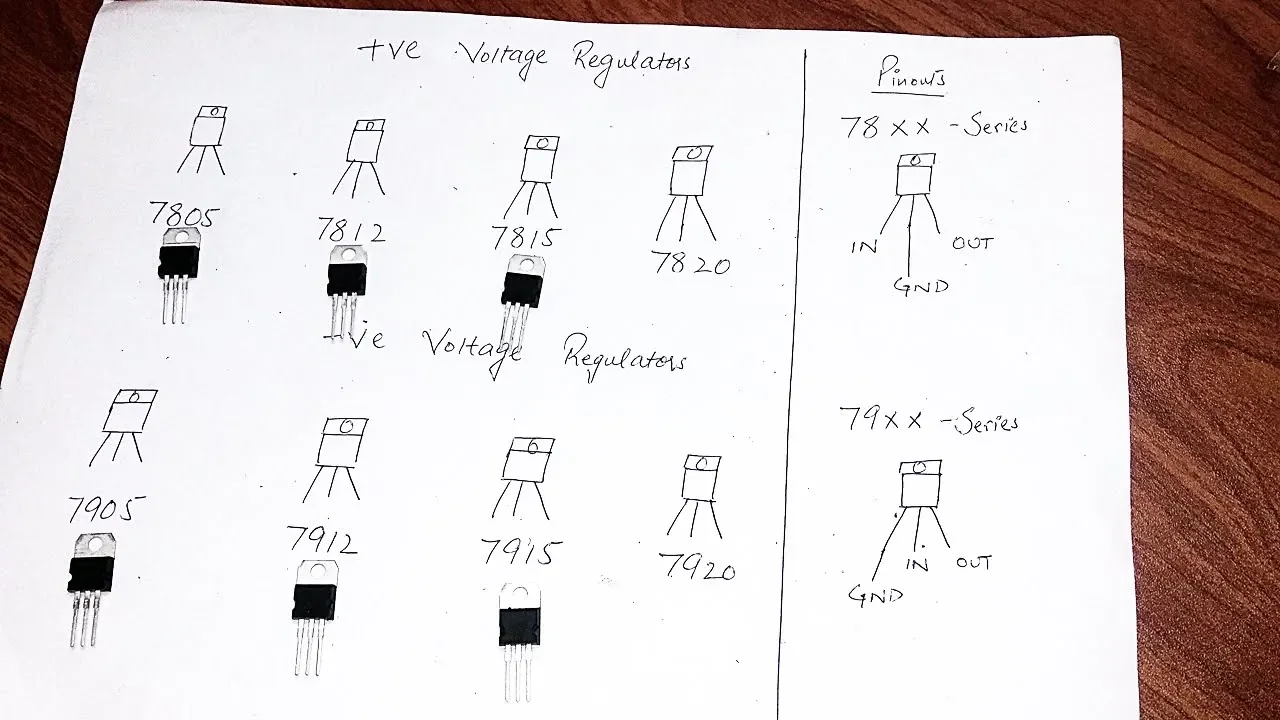
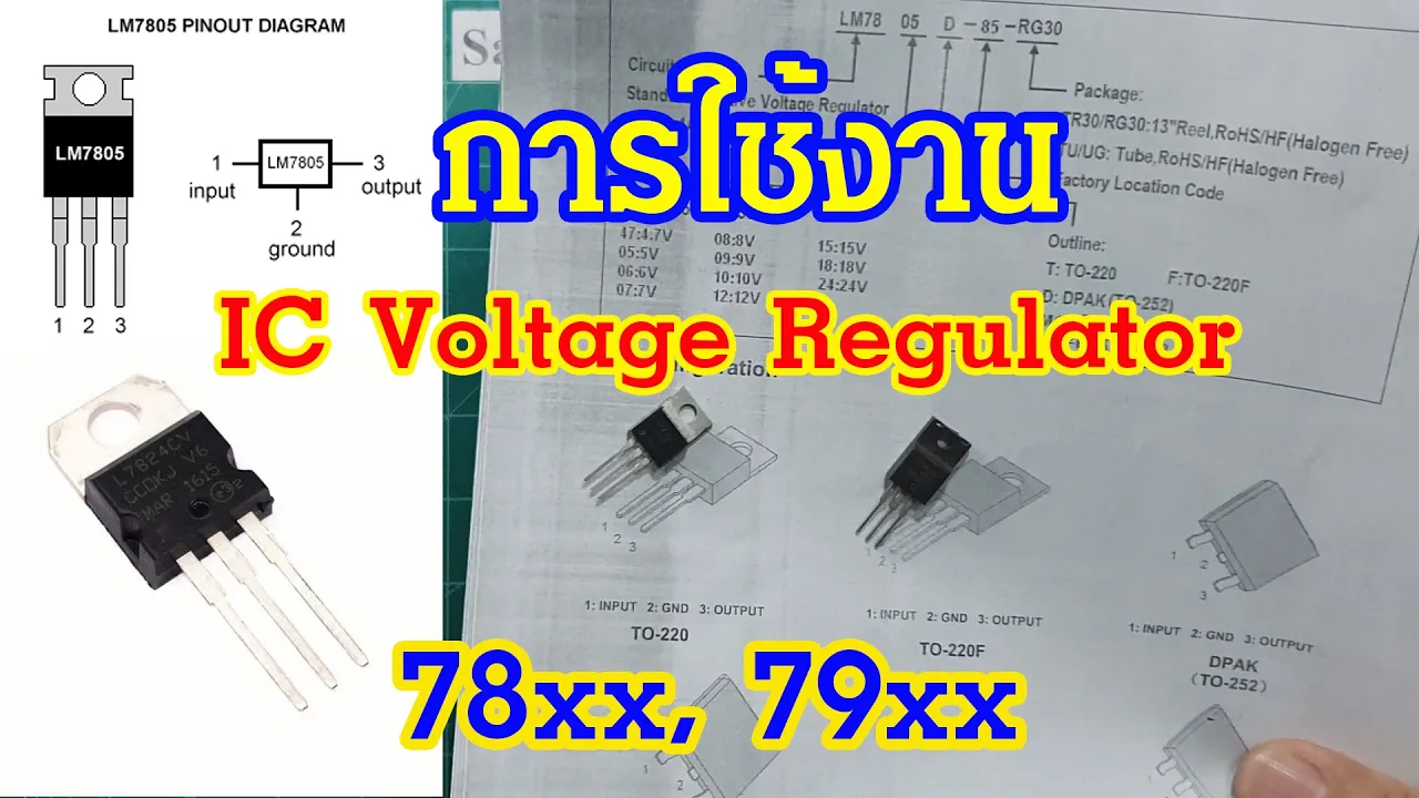
Familiarity with linear voltage regulator ICs (such as the 78xx and 79xx series) and how they maintain stable output voltages.
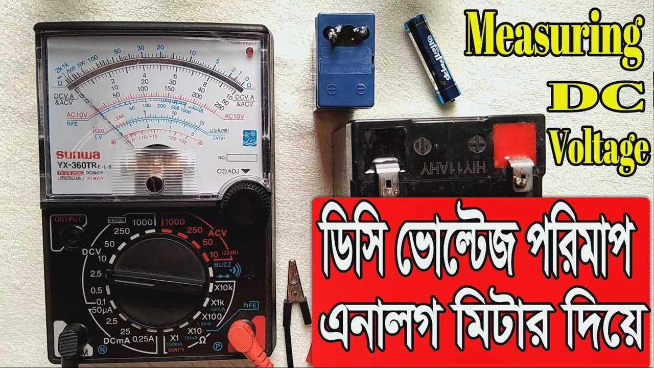
Basic electronics workshop skills, including schematic reading, through-hole PCB soldering, and safe multimeter usage for measuring DC voltage and continuity.
Integrating the completed power supply with an NE5534-based preamplifier stage, paying close attention to proper grounding techniques to prevent ground loops.
Using an oscilloscope to measure voltage ripple, noise floor, and transient response on the DC rails under load conditions.
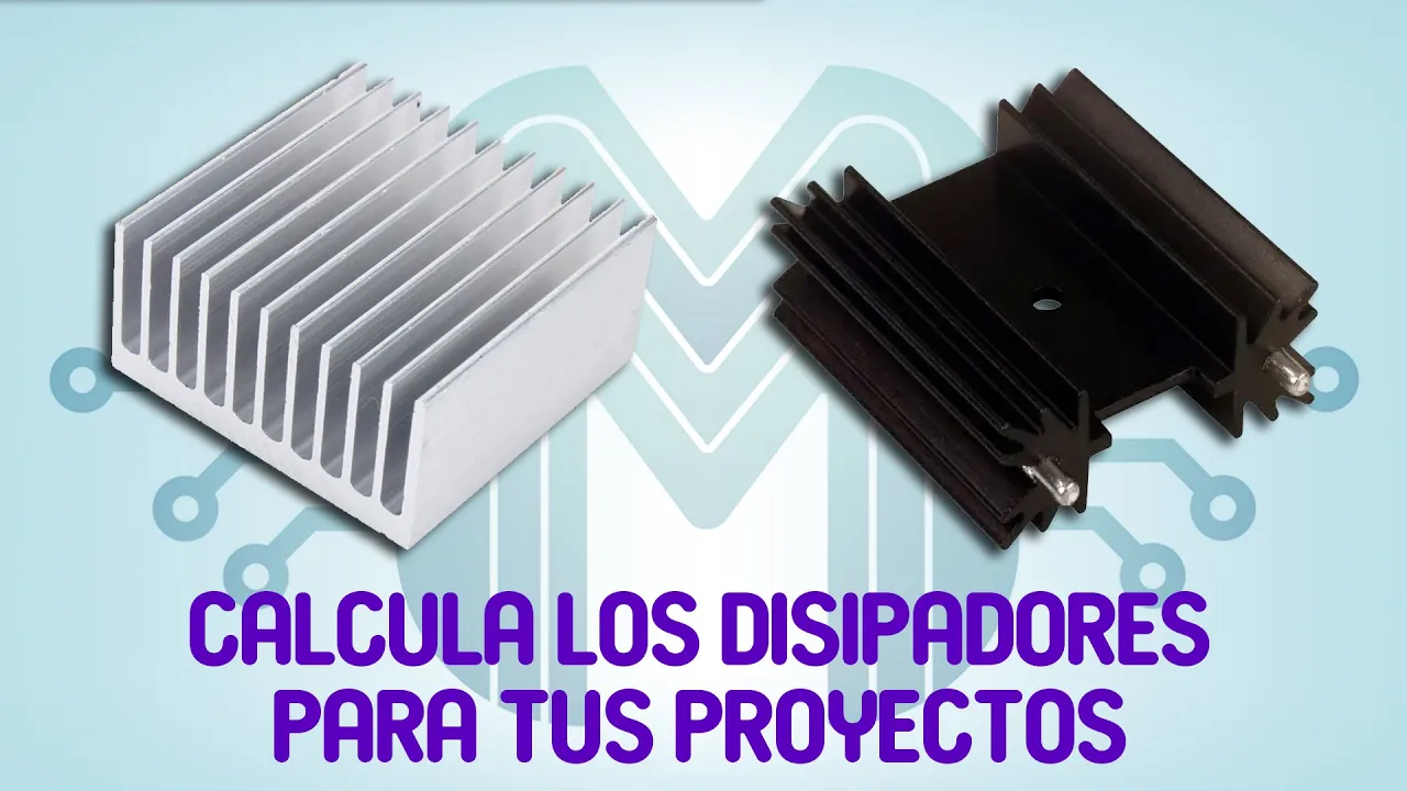
Exploring thermal management principles, including calculating regulator power dissipation and selecting appropriate heatsinks.
Advanced low-noise power supply designs, such as discrete regulators or ultra-low-noise ICs (e.g., LT3045/LT3094), to optimize high-fidelity audio performance.
219 views24likes30:34Original Release: 2026-04-30
Greetings, the Astro 30 here yet again and welcome back to AEL. Thank you for joining me.
I've got a new PCB package from JLCPCB sitting here.
Got delivered yesterday, so I'll just open the pretty little blue bag that the box comes in.
Nice.
And well, you probably tell from the title of this video what this is about, but I thought I would do the unpackaging on camera because it's fun. It's actually upside down, but that's fine cuz I need to get to this tape down here to open the box.
Aha.
All righty.
This is my little power supply PCB for the donated NE5534 stereo preamp PCB that I built in a previous video.
Link will be in the description if you haven't seen that already.
But let's get this bubble wrap open and take a PCB out so we can have a good look at it.
Very, very nice.
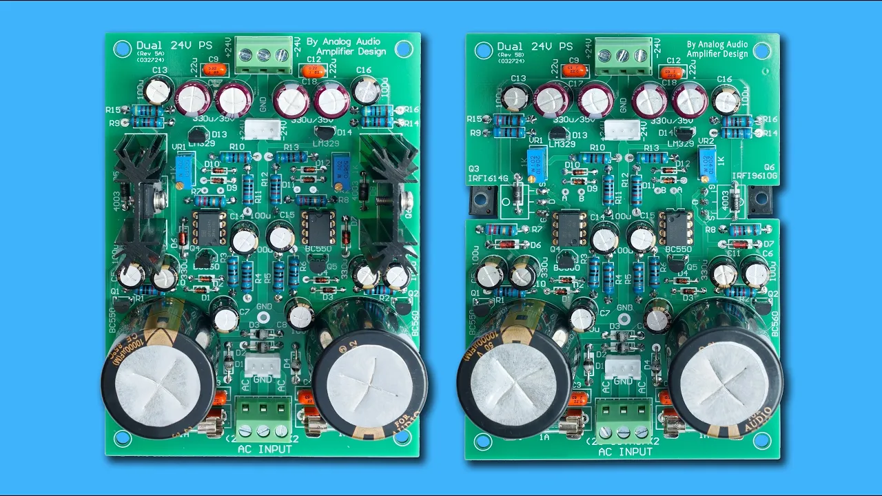
Now I'll show you the schematic in just a moment, but basically we have a muting relay here which takes the left and right outputs of the preamp and disconnects them from uh the outside world, so they're going to the RCA sockets at the back of the unit for instance to connect to a power amp.
So when the preamp is switched on, if the power amp is switched on first, you're not going to get a loud thump through the speakers as the preamp stabilizes.
Which is a common issue.
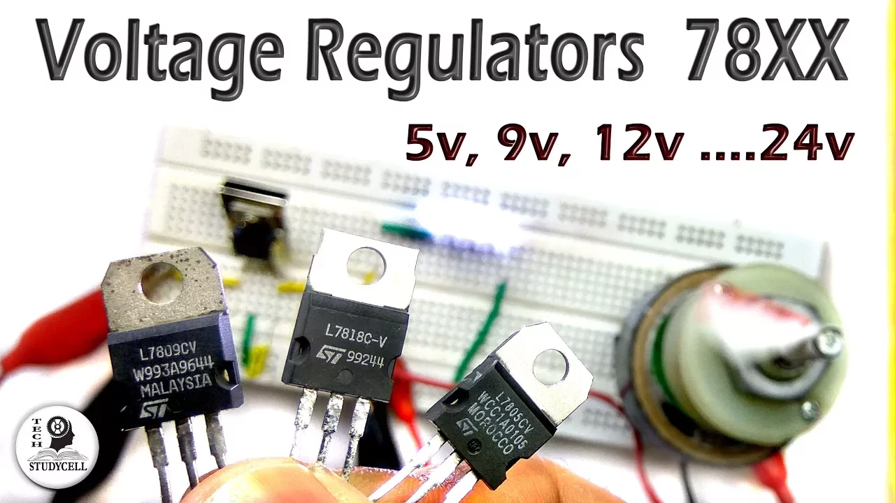
So I've got provision here for some heat sinks which are for some regulator ICs, 78 series and 79 respectively.
Produces plus and minus 15 volts uh on one rail and a second plus 12-volt rail plus ground to power say an input selector board, which is another PCB that I actually have come up with, just haven't had made yet.
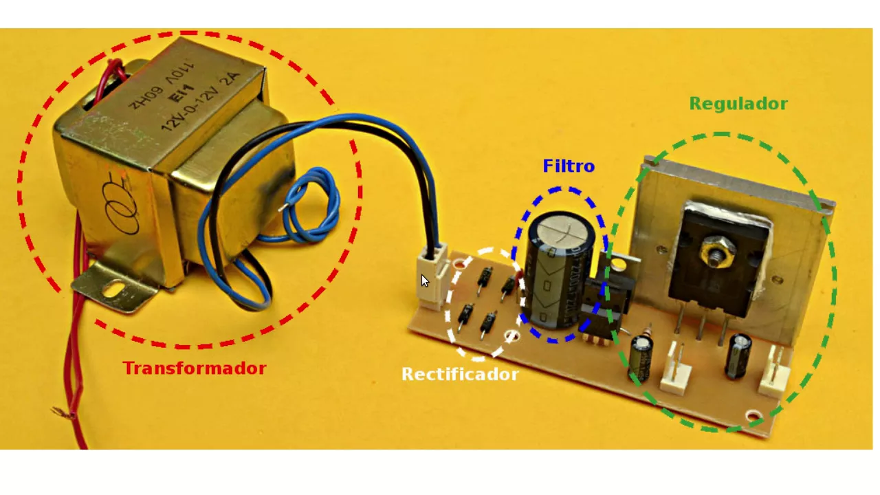
So we have an incoming AC from a transformer 15-0-15, so a 30-volt center-tapped transformer, coming on this connector here. Got a little LED indicator for the power that can go off to the LED and say a paddle switch with an indicator on it or a separate LED on the front panel.
Going through a full bridge rectifier and going through some smoothing capacitors.
Now I've chosen 2200 microfarad at 35 volt each for all four of these capacitors, so that gives us a total smoothing capacitance of about 4400 microfarad.
>> [sighs and gasps] >> So I'll explain this more when we look at the schematic.
And after we've looked at the schematic, we will build this in time lapse, even though at this point in time of the video I don't have all the components, but we will do before this video is finished.
Um I don't have the required heat sinks either.
I have to order them from Altronics cuz the ones from Jaycar are physically larger than this footprint and they're going to touch each other anyway, so that's no that's no good.
So yeah, let's go have a look at the schematic and then we'll get into building something.
I don't know how this is going to come up on camera, but I have just noticed a little bump here in the solder mask.
Maybe a bit of stray copper that didn't etch off properly.
Yeah, that's uh that's weird.
I'll have a look at another PCB and see if that uh protrusion is also on it, but yeah, that's something I've never seen and I can't get the camera any closer to that uh otherwise goes out of focus.
Put that to the side and I'll grab another PCB.
Well, looking at this one, that protrusion isn't there.
So that's a manufacturing defect on that one compared to well, this one, probably the rest of them, so I don't know what happened there.
Um [snorts] might get a look at that under a magnifying glass and see if I can figure out what it actually is.
I have absolutely no fricking idea.
Um it's a bit hard to tell with the solder mask on it, but I don't really want to damage the PCB by removing the solder mask to have a look.
So it's a non-issue as long as it's not connecting to anything like it's conductive and connecting to anything important or cross anything important.
I guess that is one thing to watch with JLCPCB is to examine the PCB for things like that on both sides uh to make sure there aren't any manufacturing defects which could then lead to the circuit not functioning correctly if at all or more disastrously uh going up in smoke.
Anyway, let's go have a look at that schematic. Okay, so here's a look at the schematic. The AC from the transformer secondary comes in here on J1, which goes through a full bridge rectifier made up of D1 to D4, 1N4004s.
1-amp diodes perfectly fine for this application as it's only powering a preamp and maybe a couple of relays.
That is then smoothed with these four 2200 microfarad at 35 volt caps.
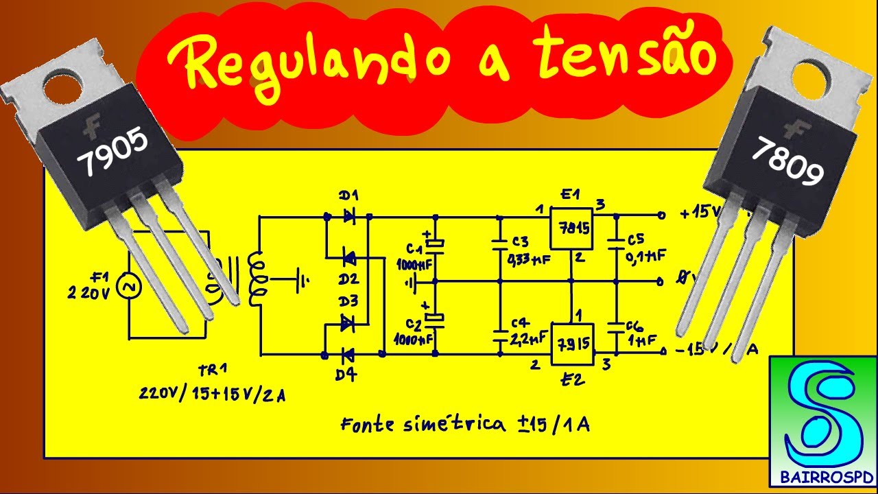
Any high frequency is rolled off with these 100 nanofarad capacitors forming our positive and negative rail. The positive rail goes into a LM7815, which is a 15-volt positive regulator, which forms our positive 15-volt output.
We have a little 10-microfarad capacitor here close to the IC on its output and another 100 nanofarad for extra high frequency smoothing. The negative rail goes into an LM7915 voltage regulator, which produces our negative 15-volt rail, again smoothed with a 10-microfarad capacitor near to the IC, and any high frequency rolled off with this 100 nanofarad capacitor also. VCC line is then tapped into this third regulator, a 78112, which gives us a 12-volt positive voltage output to go power say an input selector as I just mentioned, which only just has this little 10-microfarad capacitor near the IC on the output and a 100 nanofarad for extra measure on the input. Not that it's really needed because it's coming off of the VCC point up here, which already has one.
Conversely, one AC input then comes through this fifth diode here, D5, another 4004.
And this is a half-wave rectifier, which is then smoothed with this 100 microfarad 35 volt capacitor to ground.
And that is feeding the collector of Q1, which is giving the collector current to this transistor, which is actually driving this relay down here. This 22k resistor and a 100 microfarad capacitor at its base here form an RC delay constant. This connects to the VCC point up here.
And this gives a turn-on delay of roughly 3 seconds.
So the relay will engage after 3 seconds. This sixth diode is a back EMF diode for the relay. And the other side of the relay goes through this 220 ohm 1-watt resistor just to slightly limit the current that's being uh supplied through the relay because the voltage that's going to be here is going to be roughly 17 volts. The relay is only rated at 12.
So this just limits the current, which again reduces the voltage, so the actual voltage across this relay coil ends up being around about 10.9 volts, something like that. The pull-in voltage of this particular relay is eight. All the job of this relay is is just to disconnect the output of the left and right channels of the preamp before it goes out to an output connector on the back panel for instance, so that you don't get any clicks and pops when you turn it on or off. And you don't get loud thumps through your speakers if you don't turn the power amp on last or off first in that sort of scenario.
Cuz this is going to be a self-contained unit, a preamp only basically with no power amp, so it can then be connected into a separate power amp. Finally, we got this VD connection here after the half-wave rectifier, which connects to this point here, which is just a simple LED and dropper resistor. This is just its power indicator. That can be a LED inside of a switch or it can be a separate LED on the front panel. It doesn't matter, it's just a power indicator. Anyway, that's the schematic and there's not much more to talk about it. It's a very basic circuit. So let's get constructive and actually build it and see if it works.
>> [music] [music] [music] [music] [music] [music] [music] [music] [music] [music] [music] [music] [music] [music] [music] [music] [music] [music] [music] [music] >> All right, about 20 minutes later, the board is assembled for the most part.
I'm just waiting on an Altronics order to arrive. [music] Which will have the relay and the heat sinks. Um might have an issue [music] with the fitment of the heat sinks for those footprints being really close to each other.
But I shall soon see [music] when I have the physical things in my hand.
Now, soldering to this board is kind of reminiscent of desoldering components on an old Philips television from the 1970s.
Mhm, which is kind of a weird smell.
But um I just want to check the height of things cuz this is going to be mounted in a one unit rack mount case.
So, I need to add 10 mm on the other side for the standoffs.
And I get to the height of the capacitors mhm, 37 and some change.
So, you can't see that. So, let me just re-position.
So, it's something like 37 and 1/2. The internal size of the one unit rack case I'm going to use is 38. So, that's awfully close to these um parts of the capacitor, the tops of the can here, touching the case lid.
So, I could do that. Uh I could stick some things on top of them to just make them insulated in case the lid of the case does actually make contact with it.
But I might just use a bolt and two nuts on the underside of each of the standoffs here.
So, it's getting as close to the inside of the bottom of the case as possible with some four nuts on top.
So, that will give me roughly 5 mil.
So, if I measure this again at 5 mil, that brings it to uh 33 and some change.
About 34.
So, that leaves a good 4 mm of space between the tops of the capacitors and the inside of the lid.
So, that's upside down. So, the electrons are going to fall out.
So, I might just use the double nut method for mounting it instead of standoffs cuz I was going to use 10 mm ones. They're going to be probably on the too long side.
It'd be nice if I could get them in 5 mm, but I can't very easily.
Anyway, I'm just waiting for the parts to turn up so I can install them and the regulators, etc. And then we can actually test this on a transformer. I've got a 15015 knocking about in the corner somewhere.
And we'll see if this uh goes up in smoke or it uh just works.
I'm assuming it's just going to work.
Well, the parts arrived, but I'm not sure why they put it in a large cardboard box for three items.
Whatever.
Okay, seems just like a waste to me.
They could have put it into a post bag.
But they didn't.
Oh, and always be safe with knives.
Don't pull them towards you.
He says as he does exactly the same thing.
All right, let's get a look in here. A look. A look.
Oh, I love these things.
Cuz they're fun to do this with.
Yeah.
I'll um play with that later.
All right, got some 100 nanofarad capacitors. That's fine.
The relay, which I need.
And the three heat sinks, which I now have to see actually fit on the footprints because they're actually wider than the footprints.
They're 16 mm in width. So, I don't know if they're going to even fit close together or interfere with each other. So, that's the first thing we're going to find out.
And just get rid of the box.
A catalog for May.
So, 68 W compact soldering station.
Mhm, 100 bucks. Save 26.
Yes.
Booming 200 W RMS 10-in subwoofer. Uh this is kind of like an electronics porn magazine, to be honest.
Even though it's not a magazine, it's a pamphlet.
Mhm, anyway.
Okay, so let's get a look at these heat sinks and see if they're going to play nice on the PCB here.
At least they fit through the holes, which is nice.
Now, I'm already seeing interference problems.
Big time.
That one fits all right.
That one is a bit on the tight side.
They're also backwards.
I'll try and put them the right way around. Actually, might swap these two over.
So, that fits in okay that way.
It's just this one seems to be acting weird.
I think the issue is this footprint is slightly closer to this other one than these two are. These are fine.
So, in order to get that to fit flush, I'm going to have to isolate the devices anyway.
What I might do is take a file to the sides of these pins here just to sort of like shave a bit off so it can uh which way do I need to do it?
Well, it wouldn't be the outside edge, it'd be the inside edges here.
Just so it's got some room to move that way. So, >> [sighs and gasps] >> cuz I'm looking at it upside down.
Needs to be this inside edge. Now, I shouldn't have to take off too much, I wouldn't have thought.
It doesn't matter if I scrape off the uh bottom of the heat sink here. It's fine.
Probably should use a better grade um file.
Yeah, I'm going to have to use a more aggressive file.
Give me a minute. Yeah, I didn't want to do that, but it's um much flush much flush much more flush now, so that's the main thing. And anything that was scraped on the side of the heat sinks at the bottom.
>> [snorts] >> Okay, so I can basically solder them in.
So, these are just blind holes, so Okay.
Should have put this back in the jig.
Would have been better than tracing it around the desk, but mhm, whatever.
Okay, so now I'll put the problem fitment one in.
Which should actually jam itself.
Oh, it actually fits better in there than it did at the other side. Of course it does, cuz that's not the issue.
The issue's over here.
Okay, so As you can see, I'm soldering these in first before I put the ICs on.
Um because well, going to kind of have to anyway. All right, now the final one.
All right, they're soldered in. So, now I can just let these heat sinks cool down naturally cuz they're going to have quite a bit of heat on them.
And then I can mount the devices.
First though, I'm going to mount relay.
So, we can cross that one off the list.
It fits perfectly.
Uh use this screwdriver just to prop the relay up against the board when I hit it with some solder.
Okay.
Make sure that it's flat.
Which it is now.
And then I can solder the rest of the pins.
Now, the solder smells sweet now for whatever reason.
Okay.
So, it's starting to look like something.
Mhm.
All right, so let me get some isolators.
You can see the difference in the gap between here and that one then this one.
Mhm.
I'm going to get some isolators, uh some bushings, and the three regulator ICs which are just knocking about back here.
Install them in the correct places, and then we're one step closer to testing it.
Yay.
Okay.
Let's double check. 79 should be there, the 78 should be there, and the 12 V one should be there.
Okay.
Now, I can solder these ones in.
Okay. I think that's done.
Okay.
So, now I'm ready to actually test it.
So, I'm just going to go grab a transformer.
Before I do that, I should double check that the um ICs are indeed isolated from the heat sink.
I don't know if I can get a good um So, it looks like down in there is a good point.
That one is fine.
That one is not. Mhm.
Well, of course it's going to be idiot. It's the screw I was touching, not the actual device.
So, yeah, those are the devices.
That one's not making any contact though.
I need a good ground point here. The screw doesn't seem to I'm touching on the screw itself, it should be fine.
Yeah.
Isolator.
Isolator good, so it's not going to blow up when I turn it on.
But, still got to put it through a dim bulb.
All right, I've got the transformer sitting here off to the left. I'm just going to pop an LED in through the LED hole so that's making contact with the board.
This is non-conductive foam. It's just there to stop it shorting on anything nasty that might be on the desk. So, I plug the secondary into the board.
And dim bulb is not bypassed. So, here we go. 3 2 1.
Well, we've got an LED, that's a good sign.
So, I didn't hear the relay go click, but I can find out whether that's engaged or not by measuring between Oh, yeah.
And if I turn it off, I did hear it go click.
Excellent. All right.
It's very quiet, so I can't really even hear the relay.
So, I go into voltages, and I'll put one probe on ground.
And we have positive 15 V there.
Negative 15 V there, and we should have 12 V or thereabouts there.
Excellent. So, that is working.
However, that dropper resistor which is 1 K for the LED might be a bit on the low side. It should probably be a little bit higher.
But, yeah, I'll work that out later.
Um as for that resistor down there that's limiting the current to the relay, I can't really feel anything.
That's fine.
Um What I want to try and do is I want to try and just have a look using a continuity tester on the other multimeter which has already got these handy little alligator clips already clipped to.
Is if we somehow get it to All right.
Now, I want to see how long it takes for the relay to engage.
I don't think it matters if it's shorted to ground on one side as long as the other one isn't. So, here we go. 3 2 1.
>> [bell] >> That was about 2 seconds.
So, what I'll do is I'll bypass the dim bulb now.
And 3 2 1.
About 2 seconds.
Excellent. Well, I'm happy with that.
Now, I'll go into the voltage scale, and I will just uh look at the output.
And it's currently 17 16 V now and dropping cuz there's no bleed resistors on this um circuit board. And we're still hovering around about 12. I just want to make sure that uh these filter caps are bled off to a safe level so I can handle the PCB.
We're at uh 6.1 V now.
And falling, so most of the charge is being eaten up by the regulators.
We're now down to 3.8, 3.6, 3.3.
I know you can't see the meter, but you're going to have to trust me. It's now at 2.7.
So, it's pretty well now safe to handle so I can unplug the secondary.
And I'll remove the LED out of circuit cuz it's no longer needed.
And I'll pop it back in the breadboard where it came from next to me. Right.
And we're at 1.4 V, that's pretty good. That's fine. I can handle that now.
So, that's this little preamp power supply Just kidding.
That's that little preamp power supply built, tested, and working. I'm a little bit annoyed about this footprint being close to this one.
Meant filing down the ends of the um pins just to make it fit in the hole better and give it a little bit of room, but uh it's fine.
I could have used smaller heat sinks, but I like that.
So, that's going to look quite neat in a two-unit rack case.
I just noticed that this uh seal pad is taller than the others.
And slightly shorter at the bottom. It looks like uh they might have put the hole in a different spot on that one.
Mhm.
Manufacturing defect, I guess.
But, yeah, that's this little preamp power supply tested. I'm happy with the result. It's working.
Um And the audio channels are being connected and disconnected uh respectively as they should. So, all well and good.
So, that's going to about do it for this video. I hope you enjoyed it. It's taken me about 2 weeks to make it because I had to order stuff.
And um yeah, so if you did like [laughter] it, give me a big thumbs up down below.
That'd be great.
Anyway, I shall see you in the next video.
Catch you next time. I'm The Astro 30, and if you enjoyed this video, please remember to go down below, like, comment, and subscribe if you haven't done so already. And as always, this is the Astro 30 saying, "See you. Thanks for watching. Have a great day."
>> [music] [music]
Up Next

27:28
K-Pop: The Global Rise and Cultural Influence of South Korean Pop
@bbcradio1
781.4K views•2018-01-19

12:54
Triumph of Orthodoxy Icon: Byzantine Art & History Explained
@BenCallan
2.1K views•2024-08-06

9:49
FastAPI vs Flask vs Django: Choosing the Right Python Web Framework
@TechWithTim
302.5K views•2024-05-26

1:42
Game of Thrones Opening Credits: A Cinematic Analysis
@gameofthrones
46.3M views•2011-04-18
Related Study Plans & Knowledge Roadmaps
Structured learning paths in General & Interdisciplinary Studies
general-studies
Elevator Engineering: History, Physics & Cities
01From Hoists to Safety Brakes: The Dawn of Vertical Lift
02Hydraulic vs. Traction: The Engineering Physics of Elevators
03Modern Speed, Safety, and Algorithms
+ 2 more learning modules
12h5 modules
Explore Roadmap
general-studies
Rubber: Material Science, History & Geopolitics
01Origins of Natural Rubber & Mesoamerican History
02The Chemistry of Natural Rubber & Vulcanization
03The Geopolitics of the Rubber Boom & Colonization
+ 2 more learning modules
12h5 modules
Explore Roadmap
general-studies
Containerization: Evolution, Logistics & Trade
01Ancient Trade & Bulk Cargo: Amphorae to Barrels
02The Industrial Revolution & Cardboard Packaging
03The Containerization Revolution: Malcom McLean
+ 2 more learning modules
12h5 modules
Explore Roadmap
general-studies
Textile Tech: Evolution, Labor & Global Impact
01Pre-Industrial Textiles: Handloom & Cottage Industry
02Mechanization: The Spinning Jenny to the Power Loom
03The Factory System & Global Labor Transformation
+ 2 more learning modules
10h5 modules
Explore Roadmap