







![অধ্যায় ৩: মৌলের পর্যায়বৃত্ত ধর্ম ও রাসায়নিক বন্ধন: পোলারন এবং ভ্যান্ডার ওয়ালস বল [HSC]](https://i.ytimg.com/vi/HB3BXjsf9UM/hqdefault.jpg?v=63b504e2)




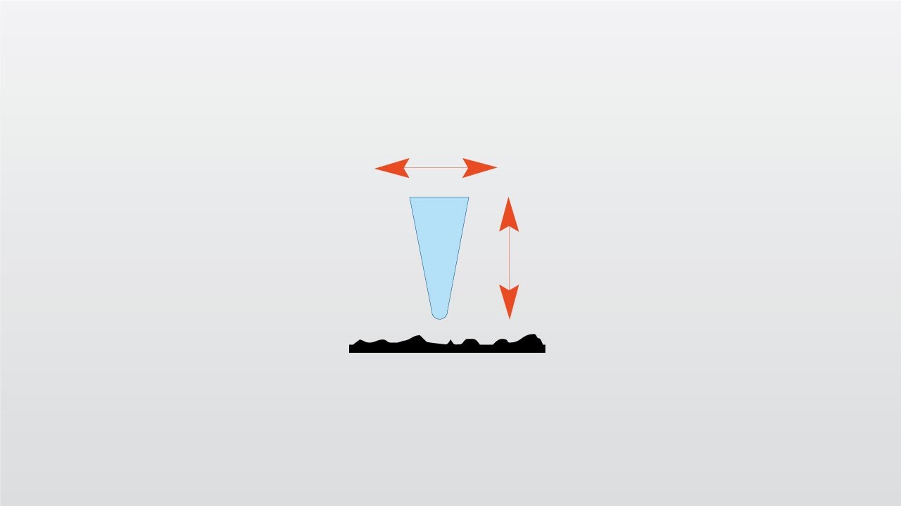

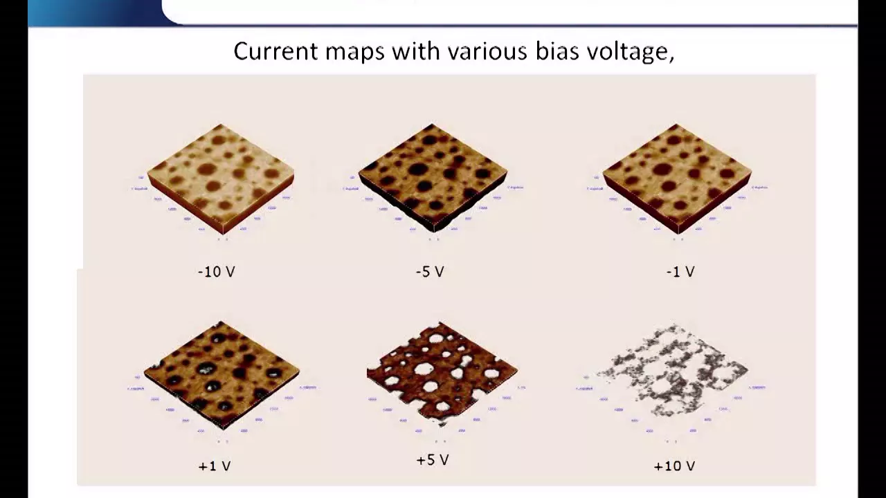



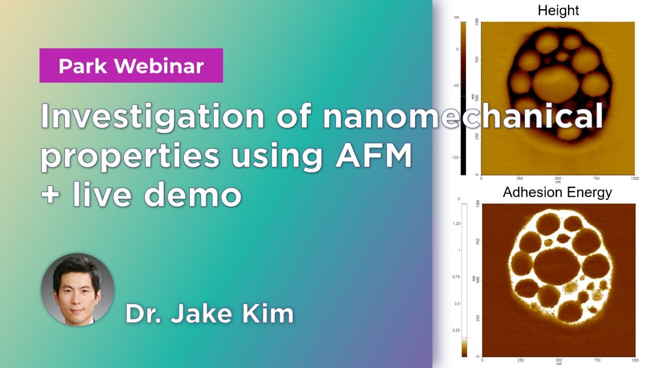
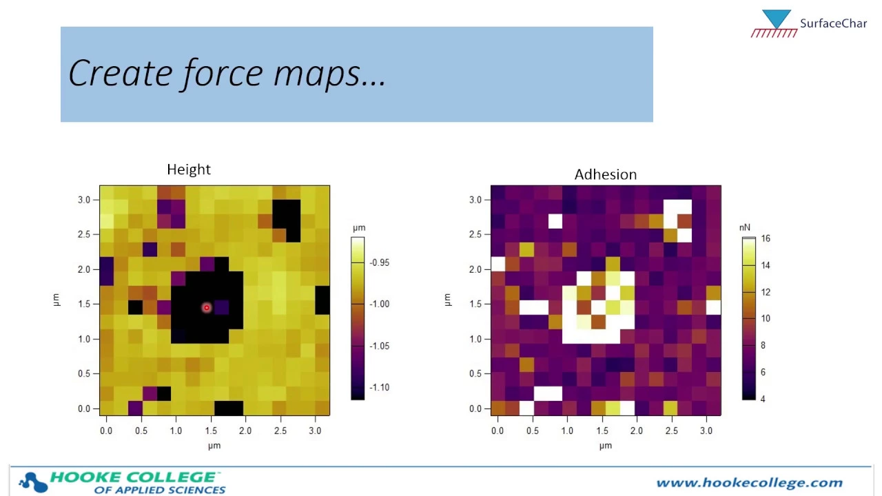


Atomic Force Microscopy (AFM) provides 3D nanoscale surface topography by measuring forces between a sharp probe (radius ~10 nm) and a sample surface using a flexible cantilever; the three primary imaging modes—contact mode (repulsive van der Waals regime, <0.5 nm separation, fast but risks sample damage), tapping mode (intermittent contact, 20-100 nm oscillation amplitude, suitable for soft samples), and non-contact mode (attractive van der Waals regime, up to 10 nm separation, minimal force but lower resolution)—each utilize feedback loops to maintain constant interaction signals while generating topographic maps, with additional specialized modes enabling measurements of friction, electrical conductivity, magnetic properties, and chemical composition.
Atomic Force Microscopy (AFM) Basics Explained
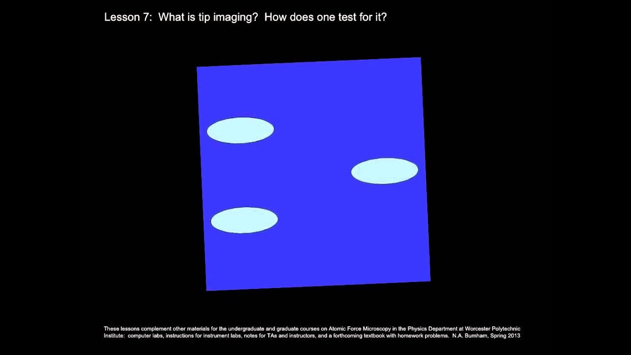
Added:hi there so today I'd like to talk to you about Atomic Force microscopy we're going to go over some of the basics here um so AFM or Atomic Force microscopy provides a 3D profile of the surface on a nanoc scale by measuring forces between a sharp probe which usually has a radius of curvature of say 10 nanometers or less and a surface at a really short distance from each other so you can bring it down to Within less than a nanometer to 10 nmet or so for probe sample separation and the probe is supported on a flexible can and then the AFM kind of gently touches the surface and then records the small force between the probe and the surface and then by maintaining a uh a signal in a feedback loop then you can generate a three-dimensional topo map like some of the ones that you show here so this was taken um by me for a project that um we did on uh measuring the Topography of we surfaces on the under tall stone tools for example so how does it measure the forces well the probe is placed on the end of a can lever which you can think of as a spring and the amount of force between the probe and the sample is dependent upon the spring constant or stiffness of the can lever and typical spring constants could range from say a tenth of a Newton per meter all the way up to on the order of say 10 or 20 newtons per meter but one newton per meter is pretty typical and then the distance between the probe and the sample surface is also going to determine the force because the force is described by a hooks law where f is equal to minus KX or F is equal to KX as you push into the surface so you have your spring constant K and then the tip um surface distance which is your X and so you've got a dependence there on those two things so typical forces can go down to say Nano Newtons or fraction of a nano Newton and high forces might be a millton but a typical would be so somewhere in the micr Newton range so the probes and the can levers are typically made from Silicon nitrite or silicon and they follow some of the same techniques that are used in lithography for making chips um and uh integrated circuits so different can of lever lengths materials and shapes allow for varied spring constants and resonant frequencies and a description of the variety of different probes can be found on various vendor sites so here I show some images from uh AF buer AFM probes domcom for example and buer is a dealer of both afms and um AFM probes and then here's another one made by a different company Nano analytic so the probes can be coded with other materials for other kinds of modes um for example chemical Force microsopy magnetic Force microscopy scanning capacitance microscopy you might want to coat your probe with something that is magnetic or conductive depending upon your Technique you might also want to functionalize the probe and coat it with um other types of chemicals or thin films depending on the application or what you might want to do so how do you make a a contact mode image well um the motion of the probe across the surface is controlled using a feedback loop and a pzo El electric scanner so pzo electric material is a material that if you apply a voltage it will deform the Crystal and you can apply a known voltage getting the crystal to expand or contract by some known amount and that's how the motion of the um Cal lever is controlled and then the uh deflection of the probe is measured by a beam bounce method so you have a laser that's bounced off the back of the canal lever onto a position sensitive photo di detector that usually has four quadrants um the detector measures the bending of the canned lever as the tip is um scanned over the sample and then you have a feedback loop which maintains a certain position of the laser on the photo diode as the tip is scanned over the sample by adjusting the canal lever position by applying a voltage a known voltage to the Paso and then the necessary movement of the Paso is monitored for each pixel in the image and then that's used to create a topography map and so that's how um contact mode images are created and generated now the feedback loop can monitor other types of signals um for example if you're doing tapping mode or non-c contct mode the feedback loop um you still have the laser bouncing off the back of the can lever but instead that um laser beam is allowed to move or oscillate and then a certain amplitude of oscillation for example is maintained so um the same type of concept for different modes uh but uh slightly different signals monitored so the types of forces that are measured if you look here as you approach a vary your tip sample distance then you're getting into different regimes of forces between the tip and the sample and so those are marked here on this figure the dominant interactions at Short probe sample distances in the AFM are these Vander walls um interactions long range interactions like capillary electrostatic and magnetic are significant further away from the surface and these are important in other SPN methods of analysis we'll talk about other modes at the end of the talk but during contact with the surface the probe predominantly experiences a repulsive Vander walls force and this is contact mode and that leads to the tip deflection um described um in a previous slide and then as the tip moves further away then you have your attractive vanderwell forces and those are dominant in non-c contact modes that we'll talk about here in a second okay so there's three primary Imaging modes in the AFM these are the typical ones that you'll find on other AFM like I said we'll discuss other modes of operation later in the talk but the three primary ones are contact AFM and that has a tip sample separation of less than half an anomet say and then you have intermittent contact or more commonly known as tapping mode AFM where the uh tip and Canal lever are oscillated over the surface and then the tip gently Taps the surface at the bottom of that oscillation and in those the um the distance between the tip and the sample ranges between half a neter to about 2 nmet and then you have non- contct AFM where your your tip of your surface never actually touches the tip and never actually touches the surface but it's wiggled over the surface and that can get further away up to 10 nanometers away for example so let's first talk about contact mode AFM when you're in that repulsive Vander walls regime um so first of all you only want to do this with samples that have relatively hard surfaces because your tip is constantly touching that um sample and so that leads to one of the main disadvantages of contact mode AFM which is that the tip can actually damage the sample or deform it if the sample is too soft but um when you're in this repulsive Vander wals regime your spring constant of the can lever is less than the stiffness of the surface and so the canal lever bends and the force on the tip is repulsive and then you maintain a constant Canal lever deflection using using that feedback loop I described earlier and the force between the probe and the sample remains constant and then you use that to generate an image of the surface so the advantages are that this is fast scanning and it's good for rough samples and it's used in friction analysis which I'll talk about in just a second but the disadvantages of course are that it can scratch the surface as we talked about earlier now if you um don't want to deform or scratch your surface then you can uh stay in contact mode and switch to a lower spring constant Canever because of course at a base hooks law f is equal to KZ so if you switch to a lower spring constant you're not pushing as hard um or you can switch to one of the tapping or non- contct modes and then that is less likely to deform your sample however sometimes and this is worth mentioning researchers want to scratch the surface for whatever reason maybe they want to write a pattern on the surface or to form the surface on purpose like for example This research group here whose image I uh stole and credit um they introduce defects um like scratches with the AFM and then they um submerge the surface in a liquid and do an electrodeposition electr plating basically onto that surface and then the metal um preferentially deposits um on the scratch sites because the way that they deposit it is they apply a voltage to that surface and of course when you apply a voltage your electric field is going to be higher at areas that have smaller radius of curvature and if your electric field is higher then you get more electrodeposition of the metals at that point and so they're using it to to nanop pattern their surface um by scratching it another benefit of contact mode that you might want to exploit is that it can measure friction on the Nano scale so you can see what you typically happens in an AFM image is that you scan a line and then you scan back over that same line so it scans each line two times the back and the forth the lateral forces though that are on the can labor can cause it to bend sideways as you can see in this little cartoon over here and that can cause the deflection of the laser spot on the photo diode from left to right well you can monitor the deflection of the laser spot on the photo diode um voltage as it deflects from left to right and then that can be used to generate a signal as is shown here and then that signal the voltage of the signal can be related to the force the lateral force or friction of the tip on the surface so higher friction surfaces reflect the can lever more laterally which means that you can measure a higher friction Force um so you can actually measure friction on the Nano scale and that's been done a lot I've done it myself for example during my PhD thesis okay moving on to another really common mode in AFM we can also um talk about tapping mode also called intermittent contact mode so in this the Imaging is similar to contact however in that mode the can Canal lever is oscillated at its resonant frequency um res frequencies typical can be um in the tens to hundreds of kilohertz range they have oscillation amplitudes of 20 to 100 nanometers or so so typical oscillation amplitudes so during this mode the probe lightly Taps on the surface sample during the scanning um and it contacts the surface at the bottom of the swing and by maintaining a constant oscillation amplitude that means that you're maintaining a constant tip sample interaction and that um allows you to generate a map um of the surface so the advantages of this it allows high resolution of samples that are easily damaged or loosely held to a surface and so it can be good for soft samples like Plastics polymers or biological samples however it's more challenging to do this in liquids typically if you want to do imaging and liquids you do it in contact mode it's not impossible but it is more challenging and sometimes slower scan speeds are needed however I'd like to say that these days tapping mode is one of the you know most common modes that people will try when they just stick their sample in the microscope they just kind of default to tapping and then go from there depending on what they want to figure out there's another um Mode called non- contct mode this is a lot less common because it's more difficult to do but this imag is in the attractive Vander wals regime and in this mode the probe doesn't actually contact the sample surface at all but it oscillates above the surface kind of in this absorb fluid layer on the surface during scanning it's important to realize or note that all samples um that you image in air in ambient conditions have some liquid absorbed on the surface and this is just due to the humidity in the air it doesn't have to be us spilled water or put water on the surface um so that's important to remember whenever you're doing AFM so using a feedback loop you can monitor changes in the amplitude of oscillation due to those attractive Vander walls forces um and then you can measure your surface topography now of course the advantages here are that there's very low forces exerted on that sample and that means that your probes last a really super long time um and you practically never damage your um surface however this mode often has lower resolution um and contaminant layers on your surface can interfere with the oscillation so oftentimes people don't do this mode unless their um AFM is in an ultra high vacuum chamber um and that allows you to do the best job of Imaging another thing people typically like to do with atomic Force microscopy is to take Force curves okay so what you do in a force curve is you measure the amount of force felt by the canal lever as you bring your probe tip into the surface and then push into the surface um to some specified force and then you begin to pull out of the surface and release so you're going in and out so this isn't raster scanning where you're scanning in sort of an array over the surface in a force curve you're staying at the same point laterally on the surface and you're moving the tip in and out like that okay so there's a little cartoon here first the tip starts and it's not in contact with the surface at one that's in the red part of the curve here and then eventually it gets close enough to the surface where those attractive Vander wals forces take over and it'll kind of snap down into contact with the surface and that's shown here in the cartoon at to and then you begin to push into the surface and eventually the canal lever deflects and bends upward and until you reach whatever specified force or flection that you set for your Force curve and then it starts to reverse Direction and pull back out now generally what happens is um your tip wants to stick to the sample due to adhesive forces between the tip and the sample so generally when you pull back out um you go to a larger distance away from the surface before that tip snaps loose and that's indicated here at position four where the can lever is actually bending down W now due to the adhesive forces in between the tip and the sample until it gets far enough away and then it kind of snaps loose and back to its free position so that's what you see in a force curve um Force curve analyses can be used to determine chemical and mechanical properties um like adhesion elasticity hardness of a surface um and rupture Bond lengths now the slope of the deflection which is shown here in the cartoon at C actually provides information on the hard Ness or stiffness of the sample from that f is equal to KZ equation and the adhesion provides information on the interaction between the probe and the sample surface as the probe is trying to break free so to measure the adhesive Force you just measure how far down the deflection is here at Point D when it snaps away from contact UM and then of course lots of times people will functionalize their probe they'll coat it with a thin film of some chemical of interest um and then that can be used to measure the interaction of whatever you've got on your sample with whatever your thin film coding is and that might be of interest for particular studies now moving on sometimes topography really doesn't tell the whole story so sometimes you might want to um use one of the many many other modes that are available in AFM so for example um lately I've been kind of interested in doing quantitative nanomechanical mapping or q&m mode and in that one what basic basically does is you're doing sort of a tapping mode um but each each tap it's measuring the um stiffness from that Force curve regime it can measure the stiffness or modulus of the surface and it can also measure an adhesive force and so you're getting that kind of information that you might get out of a force curve at every single data point on the surface that's q&m mode okay so that's really useful you can also do tunneling AFM tuna or conductive AFM often abbreviated with CFM CFM in both of those modes you can measure the conductivity of your sample which might be of interest you can also do MFM or EFM modes MFM means magnetic force microscopy and EFM means electric force microscopy and in those you're kind of doing a lift so you'll scan over the me scan over a line and you'll use that to figure out what the Topography of the surface is and then you kind of lift up and move the AFM tip back over that same region of the surface except this it's not touching say it's maybe 10 Netter away from the surface and then you measure the deflection of the canal lever due to the electric or magnetic fields that that Canever might experience now lots of times when you're doing M MFM or EFM you need special probes that have either conductive Coatings or Coatings that are um magnetic okay so these are specialized tips that you want to use you can also do electrochemical AFM mode and that you generally have your sample and tip submerged in some sort of liquid solution of interest and you're applying a bias voltage to your tip as you scan it across the surface and then you measure changes in the current um between the tip and the sample when you're doing that um and you also measure changes in topography because you can get deposition or changes in the surface when you're um scanning your tip with that electric field there um in the presence of some of these liquids that you're interested in doing a lot of chemist s use this mode you can also do scanning capacitance microscopy and this is sometimes similar to the MFM or EFM modes that I discussed earlier except um when you're in your lift mode you're measuring the capacitance um of the surface there's a little um image here that I've taken from Brooker um of a scanning capacitance mode image so the one on the left is just the topography and so you can see that there's a pattern surface here maybe in an integrated circuit or something okay um and then if you look at this SCM image of that same region then you can see that there's features present in that image that aren't present in the topographical image here on the left specifically you can see these little dots and within these dots if you know what you're looking at um then this represents areas that have been heavily doped by arsenic um ions for that particular sample and so you can see that the capacitance is different because the composition the chemical composition of the surface is different so that could be really useful um for a lot of different applications and you know there's a lot more modes out here than I really have time to discuss um they're coming out with new modes all the time um even in the 20 or so years that I've been doing this they've come out with a ton and it seems that AFM is more versatile and can do even more things um pretty much every day for example just the other day I saw that they had paired up an infrared spectrom um with AFM so that you could really take an infrared Spectrum um or at least look at peaks of interest from the infrared spectrum and scan over the surface and get chemical identification um while you get a topography map so I mean really just you know stay tuned because they're coming up with these new modes all the time and it's really fascinating some of the limitations that you might experience with AFM are that you can use it to um image all kinds of samples it doesn't matter if it's a semiconductor a conductor or a um an insulator so that's actually an advantage um however there are issues in achieving the resolution that you might want on each one of these samples so for example if you have a very rough sample or a sample where the slope is really steep um as the topography varies like so for example here you've got this little pillar well you're limited by the size or angle of your tip okay so if you've got a high aspect ratio tip with that very small angle down at the bottom of the the tip then you're going to be able to do a better job of figuring out um what the width of that pillar truly is and what the angle of the pillar truly is however if you have a really broad wide bat tip it's going to um sort of convolve the tip with the sample um and so you're going to get sort of a convolution of your tip geometry with your sample geometry which can be a limitation also limitations are um for example if your sample is too rough then your Paso it might exceed the limits that your Paso can move so for example for the AFM that we have here in gwood Hall the maximum peak-to Peak um Z motion that can be done is about 10 micrometers which isn't very much and so if your surface is a rough surface with with a large Z differences over a very short region then you're just not going to be able to see it in an AFM now that's not necessarily um you know all afms have the same limits but it does kind of give you a feeling for what the limitations of AFM might be also it can't go to low magnification so for example for the AFM that we have here in Garwood Hall the maximum lateral motion that can be done is about 100 micrometers or 0.1 millimeters and so if you want a larger image than that an image of a larger area than that it's tough to get now like I said different afms have different um limitations and can move different amounts so if that's what you're interested in you could um go to another mode or go to another company and and check on what they have available but there are going to be limitations in that respect okay um that's pretty much summing up what I want to say but I would like to give credit where credit is due here a lot of the um information that I presented in this talk came from a presentation by Wilson and bullan of Northern Kentucky University and it's a really nice brief PDF file that I'm going to put on our course website um for you to read and access it might contain a little bit more information that I didn't have time to go over in the talk um so credit where credit was due that was a really nice publication and as always please do read your textbook this is just AFM Basics and I do want to emphasize that we offer a course here in advanced microscopy um so if you're interested in that kind of thing and you'd like to learn more about AFM or sem or um uh microscopy Advanced microscopies for nanoscience in general please do sign up for that course in the fall so thanks and I'll see you in the next lecture
Up Next

Understanding Path Loss Exponent in Indoor Propagation Models
@TerraHertz
572 views•2020-10-29

Ultrasonic Transducers: Resonant Frequency Measurement and Horn Design
@imajeenyus42
229.9K views•2017-02-22

Polymer Environmental Degradation: Mechanisms & Stabilization
@iit
1.8K views•2012-07-10

How a Student's Question Saved a NYC Skyscraper from Collapse
@veritasium
22.8M views•2025-04-26
Related Study Plans & Knowledge Roadmaps
Structured learning paths in Engineering