


![[Устарело] Сравнение драйверов шаговых двигателей. Что купить?](https://i.ytimg.com/vi_webp/wKMIlZa2bqw/maxresdefault.webp)






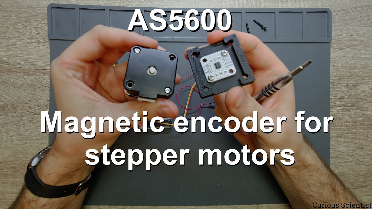
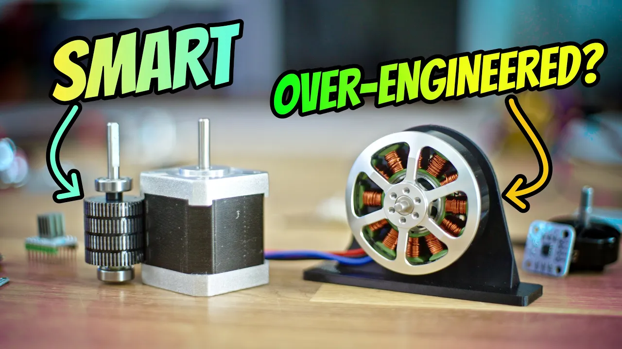




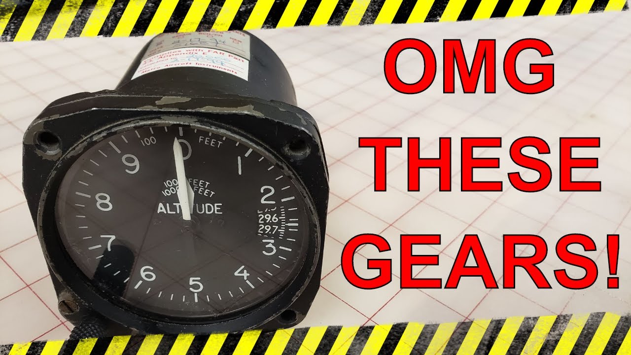




This video demonstrates how to build a functional standby compass for a flight simulator using a modified X27168 stepper motor, Arduino Nano, IR sensor, and 3D printed components. The key steps include modifying the stepper motor for continuous rotation by removing the internal plastic stop, using an IR sensor to detect the zero point (north position), and integrating the system with DCS BIOS software to receive heading data from the HSI for smooth compass movement. The 3D printed parts are finished through a process of sanding, applying acrylic spray putty to fill layer lines, and painting with flat black spray paint, with weathering added through dry brushing to create realistic wear.
Building a 3D Printed Standby Compass for a Home Flight Simulator
Added:Fundamentals of Arduino programming and basic circuit prototyping, including how to safely wire and power microcontrollers.
The working principles of stepper motors and motor drivers, focusing on step angles, microstepping, and precise rotation control.
Basic concepts of 3D printing, such as printer calibration, tolerances for interlocking parts, and post-processing of printed components.
An understanding of how flight simulator software outputs data, and how intermediary middleware (such as MobiFlight, SimConnect, or FSUIPC) bridges simulation telemetry to hardware.
Implementing closed-loop feedback systems using optical sensors or rotary encoders to auto-calibrate the physical compass card to a zero-point on startup.
Designing and fabricating custom Printed Circuit Boards (PCBs) in software like KiCad to transition the circuit from a breadboard to a reliable, flight-deck ready module.
Developing more complex mechanical instruments (such as altimeters or attitude indicators) that require differential gearing and multiple stepper/servo motors.
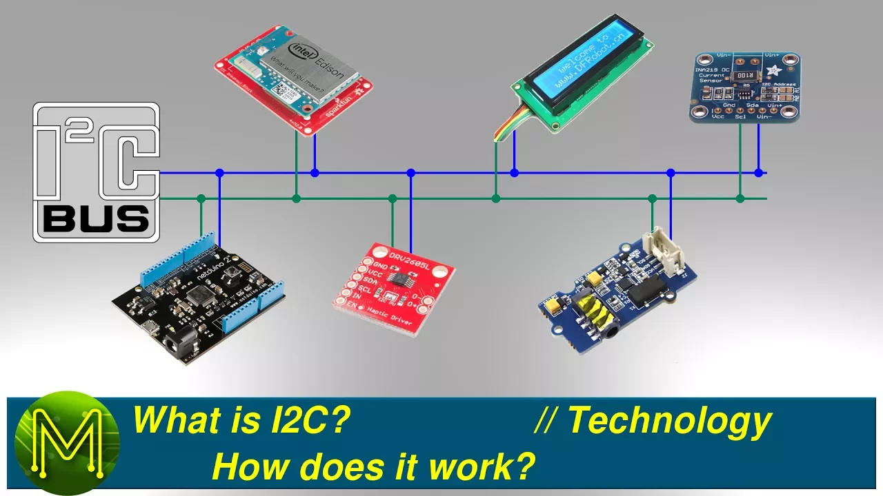
Scaling up to a multi-instrument cockpit panel by utilizing communication protocols like I2C multiplexing or CAN bus to connect numerous devices to a single master controller.
182.9K views4.8Klikes28:46Original Release: 2021-08-31
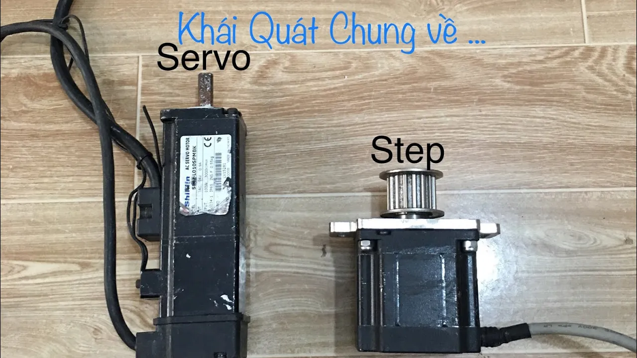
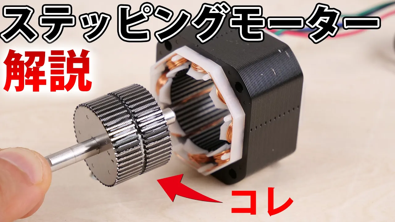
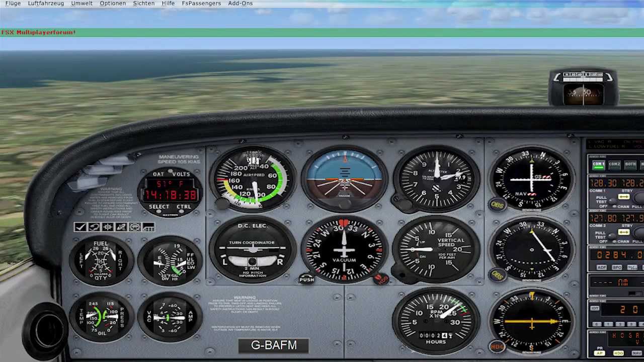
g'day everyone and welcome back to the channel for those that are new here this is my homemade a10c warthog flight simulator if you want to know how i made it or go into a bit more detail please have a look around the youtube channel or go to my website at thewardhogproject.com today's video we're going to be talking about the new addition being the standby compass i'll show you the g meter in another video only because it's not finished yet so that'll be another video on its own all right let's get into it all right so these are the electronic parts that you need to get this thing working first one is an x27168 sorry wait for your focus it's an x27168 stepper motor this is the small stepper motor that you'd find in car dashboards very inexpensive on ebay links in the description next what you need is called an easy driver board this easy driver board is to run that stepper motor so all you need to do is connect the four pins on the bottom of that to the motor section and then the these three pins here ground step and direction go to the arduino nano that's an arduino nano we probably all know what that is by now very inexpensive and controls the whole thing and then this right here is a ir sensor so it is three connections to the arduino and it tells the game where the zero point on the compass will be because i'm going to modify this to make it continuously rotating which i'll show you right now these x27 168 stepper motors they are pretty cheap on ebay they're used for car dashboards they have stops in them though um so if you turn this this shaft here that's hard up against the stop and then you turn it that way and that's a stop just there too so it's not fully continuous all the time it's really really easy to modify these so that you can have them turned continuously all you need to do is prys open the casing here just with a screwdriver you can see it's starting to pop open there's four of those around it there you go it's starting to pop open already there you go that's popped off so now you can take the cover off that's what they look like inside you can see on the inside here this is what makes it stop so this tiny little bit of plastic on there is in that channel and then that's what makes it stop so to make it continuous all you need to do is remove this and slice that tiny little bit of plastic off there with a knife so i'll do that now i'm just going to remove this here very carefully so the whole thing doesn't fall apart and then you can see just there how it's got that you just need to cut that off with a knife um simple as that now we just picked that back up set it in there and put the case back on there we go and now it freely spins continuously so i'll just write on the back of here that i know it's modified so it's for continuous rotation and then we'll mount it the problem with having it continuous right now is that you need a way for it to know where the zero position is that's where the little ir sensors come in what i'll do now is i'll show you the design of it in freecad so the first part is this motor mount again all of these files will be free to download on my website and on the links down below the video this is the motor mount this section here has the motor mounted on top of it there's a little arrow there just to show you which way is forward so you don't put it in backwards and then this section here is a arduino nano holder so that's how the nano clips into it that is actually a remix of this design right here so i can't take any credit for that it was uploaded on fingerverse and i remixed it and just um added it into my design here the next part that you'll need is the ir mount so this mount here you can see the holes where the arduino nano connects those bolts pass the whole way through and hold this section on and that holds the ir sensor which tells the arduino uno when the wheel or the motor is at a zero point next part is an led holder so i haven't 3d modeled the stepper motor but it will make sense when i show it to you in a second that section just there is designed to hold three leds in those little things you can see where the legs of the led leds go in so three leds that backlight the wheel and then the next one is the wheel so that's the actual compass wheel that will be mounted to the stepper motor you can see that there's a hole in the wheel just here where a nail mounts and then that nail that's mounted in there when the ir sensor that's on this here detects it it knows that it's at a zero point and then obviously there is a body that covers it so that's 3d printed that's the entire body sort of casing there's also a rear section that bolts on the rear there that's where your usb would connect to the arduino nano that's where the two connections for the back lighting fit and then on the front of the thing that's what it looks like at the front uh so you can see that all the front section here is laser cut you could quite easily 3d print that if you wanted to but i just used this um use my laser cutter to cut these sections here uh so just cut that out cut that out cut that out they all glue together and there's a bit of glass in there to cover it and then just here is i print that on a4 paper cut it out just on a normal inkjet printer and then glue it to the wheel okay so this is the motor mount that's just come fresh off the 3d printer uh it doesn't need to be perfect because it's not going to be seen by anything i did it out of black so no light shines through it so the arrow points to the front so this is where the face plate will be so you know that the motor needs to be mounted that way if you mounted it that way the wheel would be set all the way back here mount it that way the wheel set sort of in the center so that side there with the arrow one on is the top this side here is the bottom all you need to do is get some bolts and you just pass them through these here that goes through like that that goes through like that and then so this motor i actually drill these holes out to be three millimeter so they fit on on those bolts just do it carefully and you shouldn't have any issues at all i'll um do that now it's not rocket science or anything you just gotta very gently and very slowly drill this out [Applause] like that i'm sure a lot of people are panicking right now so i'm going to wreck this stepper motor but i got about 20 of them so if one fails which one has not yet [Music] it doesn't really matter there you go now it's drilled out for three mil you can see that the motor has um little standoffs on the bottom of it that just goes like this all right so that's basically how the motor mounts you can see that that hole in there is so i can pass the cables through so once i am finally setting it up i will solder the cables onto the tabs and they will pass down through that hole and come out to the stepper driver into the arduino this stepper driver here you can see that i've made it so it mounts upside down i did that so it would be have the slimmest profile possible so that the um this capacitor here wouldn't be sticking out so i've made it so that capacitor will fit through that hole and then just two m3 screws will bolt that on so it'll be nice and compact so that's how the stepper driver mounts and then the arduino just clicks in here it's a nice tight fit you just got to run two m2 i think they are bolts up through that which will bolt on our ir holder will stay something like that once the wheels on and then this little ir sensor just gets double-sided taped up under there like that okay so this is the wheel you can say that it's just 3d printed uh pretty simple to do ignore all these black marks i was um experimenting with gluing a bit of black paper over top of it but it didn't really work um so all i've done is 3d print that out of white uh and then printed out that file with the tape on it and basically cut it out and glued it on with a normal sort of stationary glue stick you can see that there is a nail stuck through it nothing special just a little bit of super glue on that to hold it in place and then that's what hits this um sensor so the so dcs knows where the zero point is and the zero points north so i've made it opposite opposite north there um so this is basically the complete thing ready to go this is the indexer that goes underneath it so it's run off the same arduino you can see how i've just attached some screws in there basically so it can sit there without failing on anything and then i can adjust the height of it so it's straight when it's in the container you can also see that little 3d printed thing that i did with the leds in there so they the wheel which just press fits over the top on that will be backlit by those three leds it's not super bright because of the nature of the black paper in the future i might paint this and engrave it it's a bit hard because i don't have an access to engrave on curved surfaces on my laser cutter but i have seen one that you can 3d print and make yourself so that might be the next project i'll do and the backlighting will be a bit better but from all the photos i've seen the backlighting on these things are really dim anyway this is a bit of a pain in the ass to get on straight because you need to get the wheel if you know what i mean you need to sort of do this as you're putting it on so you got to put that in there and then push it all down at the same time because once you get the arm that holds the sensor on it's a bit hard to get the wheel on all right then just put a couple of nuts on this and then those nuts hold in that arduino as well all right so you can see how that sort of free spins on the motor there and then that sensor will tell it when it's at north sensors just held on with double-sided tape you can see its connections go down to the arduino these two plugs here so it's got 12 volts in for the motor so that's 12 volts off the cockpit and then the other one is off the panel back lighting circuit and that's what does those leds in there because i've got a separate panel backlighting circuit for everything else in the cockpit i decided to run that off that circuit um it would probably be a lot easier if you just connected those leds up to the arduino because you could definitely power three leds off the arduino um and then it would be sort of a standalone unit all you'd need is one usb cable and 12 volts in for the stepper driver motor um but i've got two 12 volts in just because of my back lighting but that's that's just from my cockpit if you were making this you could probably do it a little bit separate so the the code to run this was not made by me so i can show you the link to where it is it'll be down in the description below um i didn't do any of the coding for this i found it for free already to go on the forums all i did was add the lights for the indexer and also i'll explain to you what the other changes that i made okay so here it is sort of set up on the workbench um plugged in all it's got is 12 volt power in um to run the motors and the usb enables connected to the arduino nano this is just that index are connected just to show you that it works off the same arduino so you can see that right now it's not zeroed you can see that this is just free spinning so as soon as i open up dcs bios this will go through a quick startup and zero itself so you can see that because it got a signal from dcs bias it knows to go through a startup procedure so it zeroed itself but move itself till that sensor found the nail which is the north position and it's ready to go now that dcs bias is running i'll fire up dcs and i'll quickly just jump in the jet and i'll show you that it works in the game all right so the game's running you can see the inset there and you can see the compass on the workbench so when i bank the jet you should see the compass move um so the center point will sort of be here there'll be a piece of glass with a white line on it to mimic the one you can see and then when i bank you should see it move warning now this shows the glaring issue you can see how you can see the actual one in the game is like a real compass um it's got different axis of motion it's got a picture you're on a roll like a real compass is um so i i'm getting the data for my compass straight out of the hsi so the it regardless of the angle on which the jet is the compass will always move to where your nose is headed so rather than do that sort of crazy deviation that a real compass would do because it's um got three axises of motion my compass you can see on the workbench is very very smooth it's basically pointed exactly where the nose is so i did that just by taking the data out of the hsi rather than out of the standby compass so i could get the rotation to match the one in game but because it's missing the other axis of motion it looked a bit weird it looked like it was broken like all of a sudden it would you'd bank it would stay still and as soon as you leveled out it would go really quick to the next bit i just found although it's not realistic i prefer my compass to have a nice smooth motion like it is now so it's basically pointing to where the nose of the jet is now you'll see that when it gets around to the zero point again it will skip a little bit so the code that somebody wrote not me uh the link will be in the description um once it senses zero it will re-zero itself so you won't get any sort of errors in it and you'll see that now when the nail gets around to the sensor and when we start pushing north you will watch the compass sort of slip a little bit when it re-zeros itself see that it re-zeroed itself at north again so this instrument here is what my compass is getting its data its details for you can see when i bank it's mirroring what's on that hsi rather than rather than on the actual standby compass in the game it's nice and smooth and it also it always um is pointing to where my nose is regardless of what sort of pitch angle or bank angle i'm on also please um ignore the terrible graphics i'm in the i'm on an old 10 year old computer in the garage that's why dcs is looking so terrible this is the case fresh off the 3d printer i'll use this opportunity now to show you how i finish it so this is printed at 0.2 millimeter layer height so you can you can see that it's 3d printed the way i overcome that is by sanding it filling it and then repainting it in black so what i'm going to do is just sand it with some 600 grit sandpaper just to get rid of that elephant's foot you can see there's a little bit of a gap there where it was stuck on the bed um so that'll smooth that out and then what i do is i just hit it with some acrylic spray putty the key to this stuff is to spray it on really really heavy so it fills in all those lines and then sand and paint so when you scuff it with sandpaper like that you can obviously see the lines in it the putty will fill in all those lines and then i'll hit it with sandpaper again in a final cut of black and it should be pretty smooth so there is all sanded and ready for the putty all i really do now is hit it really heavy so i'll um i'll spray it let it dry for 10 minutes spray it let it dry spray it let it dry until i get all sides you don't want to hit it on the side because it will just run down you want to fill in all these gaps so basically i just do a really heavy hit on the top then let that dry flip it same thing flip it same thing flip it same thing it takes only about 10 minutes to dry the key to this is it's not like spray paint you don't want to do light coats you want to do really really heavy coats you want to be wet so all those gaps get filled so that's how heavy you want it you'd never spray paint color like that because it'll turn out terrible but you want this to be really thick and heavy because you can sand to the top of it off and it will fill in those gaps so i don't normally wait for it to dry completely i'll just flip it over to the next side um it's probably set enough now that it's not going to run so just flip it over and do the same thing on this side let that dry so here it is with the spray filler on it all i'm going to do now is again sand it with 600 grit to get it as smooth as possible and then hit it with black spray paint so you can see that it sands really well just just like chalk this filler um basically what i'm going to do is sand it so all these dark blue lines are gone so i know it's perfectly flush and then do that on every side so you can see that's pretty smooth you can see a line straight there i'm probably going to hit that with another coat of um filler just to get that line out but it's looking pretty good all right that's probably it now i just need to again wash it off and then hit with some black spray paint and it'll be done and i'll just use rust-oleum flat black all right so here it is uh painted flat black you can see obviously the finish is a lot smoother than it was 3d printed there's still some blemishes in it but i actually don't mind having a little bit of blemish in it because it makes it look like it's real what i do is rather than try to hide the little scratches i dry brush them with aluminium to make it look like it's a dent in the middle and it comes up heaps better looks more realistic i think so that's pretty good all i do now is slide the compass or the g meter whichever one it is in there and then there's a rear thing on the back and then it gets bolted up all right so let's go do that okay so this is the front cover that i came up with you can see laser cut really simple all it is is um a couple of layers of plastic uh the glass is just glued in the rear here um doesn't look perfect on the rear here obviously it's all super glue these um screws don't actually do anything i actually ended up just cutting them off and super gluing them in there because i didn't want it to fail on the wheel in here and then that is just a piece of white tape in there cut to make a little bit of a pointer this is the main body now you can see that i had to modify it a little bit i just cut that bit out um i've fixed the design before i put it live um up on the website just because i needed to be able to slide this in there and i couldn't work out a way to get it in when it was failing on that so the rear the rear cover here i ended up printing you can see just with the two top bits holding it on so it will get held on like that um and then i ended up layers i painted all this up and then just laser cut legends in there so i can see what so that's the usb port 12 volt for the power and the panel back lighting so the first thing you do when you're putting it together is this indexer goes on the bottom here and you can see that i've made a hole here so you can fit a screwdriver in to tighten those screws so i'll do that now and then all you do now is slide this you can see how it's got those screws on it that just acts as a bump on the floor and then you just slide that in just going to make sure all the cables don't fail like that uh and it goes far enough forward that those screws hit the front of that and that's what holds it in place um those screws if if you if it wasn't flat you could just adjust those screws to get it nice and straight those get bolted into the rear panel and then the panel goes on the back and holds it up and then obviously the front piece goes on the front like that all right so that is the unit complete you can see that i just dry brushed some silver on the edges there to make it look a bit worn uh same here i actually broke the bit of plastic when i was trying to over tighten that screw and rather than cut a new one and fix it i decided just to leave it and make it look like it's really broken so i just put a whole bunch more weathering on that edge there this is just paper uh temporary for now i will i will probably cut it out of some thin sheet metal later on but i actually don't mind it like that i think it's looks a bit worn and does the job and they're just held on with some screws and then the rear here you can see there's only the two top screws holding it on you can see the usb for the nano 12 volt power and the panel back lighting if i connected the panel back lighting to 12 volts you'll see that she lights up you can see the three leds in there that's sort of 12 volt full power it probably will never be that bright but it does the job pretty well i think anyway so what i might do now is i'll just get it put in the cockpit connect it all up and we'll take it for a spin okay so here we are sitting in the jet you can see that the compass is now installed uh the reason i stuffed around with the lighting is because i wanted off the correct lighting loom so when you go down here onto my lighting control panel just like in the real jet the auxiliary instruments dial controls the backlight of the compass and the g-meter it also does all the other gauges so that controls the brightness and you can see up here the brightness is that's full brightness and then i can sort of dim it down to where i usually have it is only just a little bit brighter uh the reason i had that loom go across to that one is because it's also adjusting the g-meter i'll get into the g-meter on another video because i have not finished it yet the other thing i installed is there's a relay in that switch as well so i can turn them off with that switch just like in the real jet and turn them back on with that switch which is pretty handy so just like the real jet that controls the brightness that controls the on and off for the accelerator and the compass all right so um we'll just sort of bank off to the right here and you'll see the compass will start turning all right so you can see that it turns pretty well it's going off the hsi as i explained on the workbench so it's always nice and smooth and it's pretty accurate so you can also see that when i come down here and push the signal lap test button i get the lights on the indexes light up uh so that those leds have been run off that same arduino that's running the compass and seems to work really well i know it's not realistic they're supposed to be envy screen but i kept them colored based off my f-16 ones because i like the splasher color in it looks good i think uh one thing i wanted to add too i did originally have a plan for this i was going to put i actually bought the vibration motor out of a playstation controller i was going to install it in there and then when you fire the gun it would have shaken around a whole bunch um similar to that very famous video going around you can see this thing just goes to water when the gun fires but i decided not to do that based on the fact that it's i couldn't fit it all in this small thing if i hadn't done it it would have been about that big and it would have looked a bit weird in my opinion so i just couldn't get it all compact enough in there with enough room and mounted on rubber so it would move around enough i tried a couple of experiments in the garage and i just decided not to do it i'll get enough of our vibration anyway with my butt kicker in the seat when i fire the gun i've got it set to 120 and it shakes this whole cockpit anyway the other reason i didn't want to do it is because this whole um sort of hanger thing is only 3d printed and the constant vibration would probably just break it anyway that brings us to the end of this video thanks for watching uh stay tuned to the channel make sure you like subscribe i've got another video coming too and a whole bunch of other updates i've done like the tablet mount for one and the tablet in there running maps and i've got a new verbal gimbal down there uh and some other little things i've changed around the cockpit so stay tuned if you've got any other questions hit me up in the comments below or check out the website thewardhogproject.com thanks for watching and i'll see you on the next one you
Up Next
9:35
HX711 Load Cell Calibration with Arduino for Accurate Weight Measurement
@ElectroniClinic
22.7K views•2018-10-12

12:54
Triumph of Orthodoxy Icon: Byzantine Art & History Explained
@BenCallan
2.1K views•2024-08-06

9:49
FastAPI vs Flask vs Django: Choosing the Right Python Web Framework
@TechWithTim
302.5K views•2024-05-26

1:42
Game of Thrones Opening Credits: A Cinematic Analysis
@gameofthrones
46.3M views•2011-04-18
Related Study Plans & Knowledge Roadmaps
Structured learning paths in General & Interdisciplinary Studies
general-studies
Elevator Engineering: History, Physics & Cities
01From Hoists to Safety Brakes: The Dawn of Vertical Lift
02Hydraulic vs. Traction: The Engineering Physics of Elevators
03Modern Speed, Safety, and Algorithms
+ 2 more learning modules
12h5 modules
Explore Roadmap
general-studies
Rubber: Material Science, History & Geopolitics
01Origins of Natural Rubber & Mesoamerican History
02The Chemistry of Natural Rubber & Vulcanization
03The Geopolitics of the Rubber Boom & Colonization
+ 2 more learning modules
12h5 modules
Explore Roadmap
general-studies
Containerization: Evolution, Logistics & Trade
01Ancient Trade & Bulk Cargo: Amphorae to Barrels
02The Industrial Revolution & Cardboard Packaging
03The Containerization Revolution: Malcom McLean
+ 2 more learning modules
12h5 modules
Explore Roadmap
general-studies
Textile Tech: Evolution, Labor & Global Impact
01Pre-Industrial Textiles: Handloom & Cottage Industry
02Mechanization: The Spinning Jenny to the Power Loom
03The Factory System & Global Labor Transformation
+ 2 more learning modules
10h5 modules
Explore Roadmap