





![【チェビシェフ】 手のりチェビシェフ歩行ができるまで [Chebyshev Linkage]](https://i.ytimg.com/vi/9x-PHXkVp4I/maxresdefault.jpg)








![[CREO TUẤN NGUYỄN] Mô phỏng Mechanism - Bài 1 : Các liên kết động trên Creo Parametric](https://i.ytimg.com/vi_webp/eHMSnhHnhdg/maxresdefault.webp)








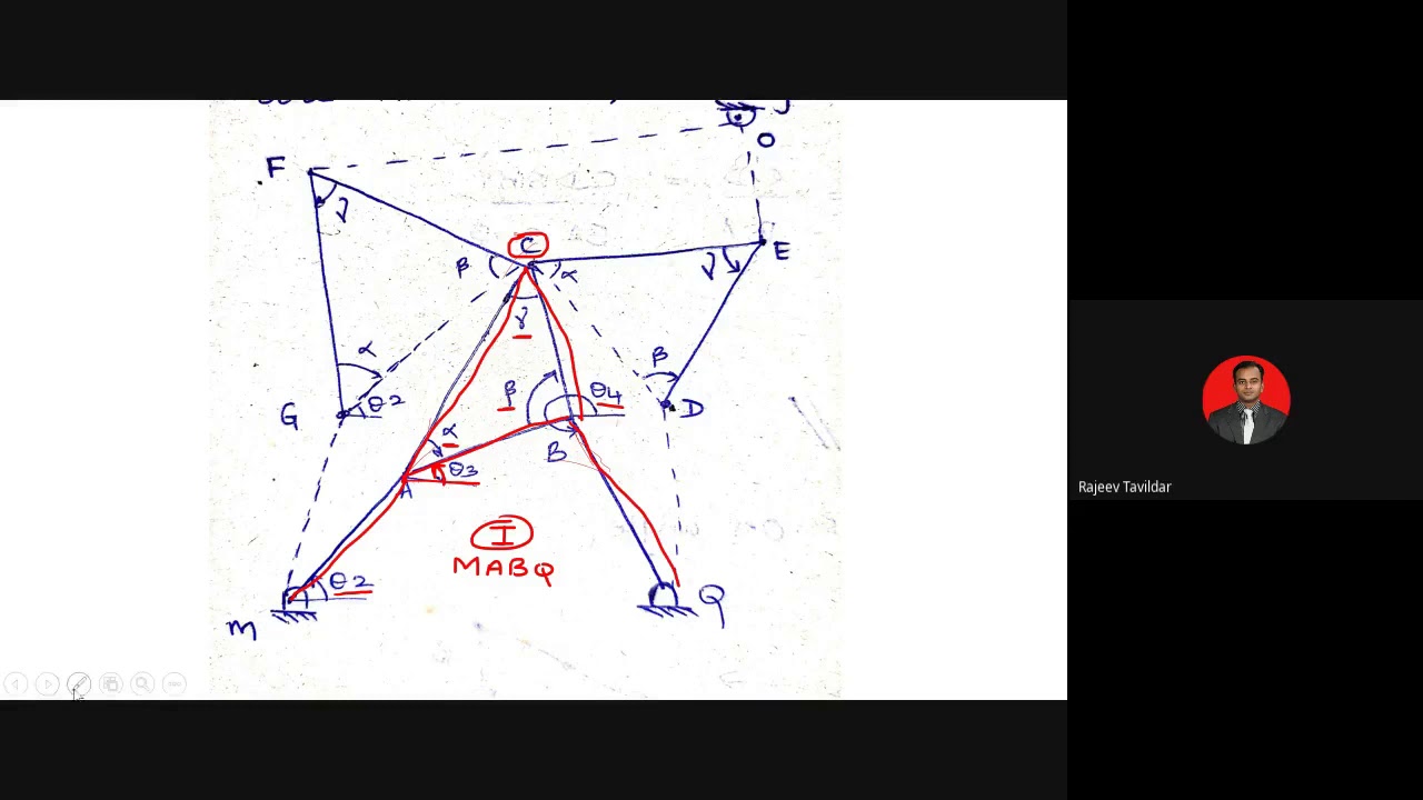

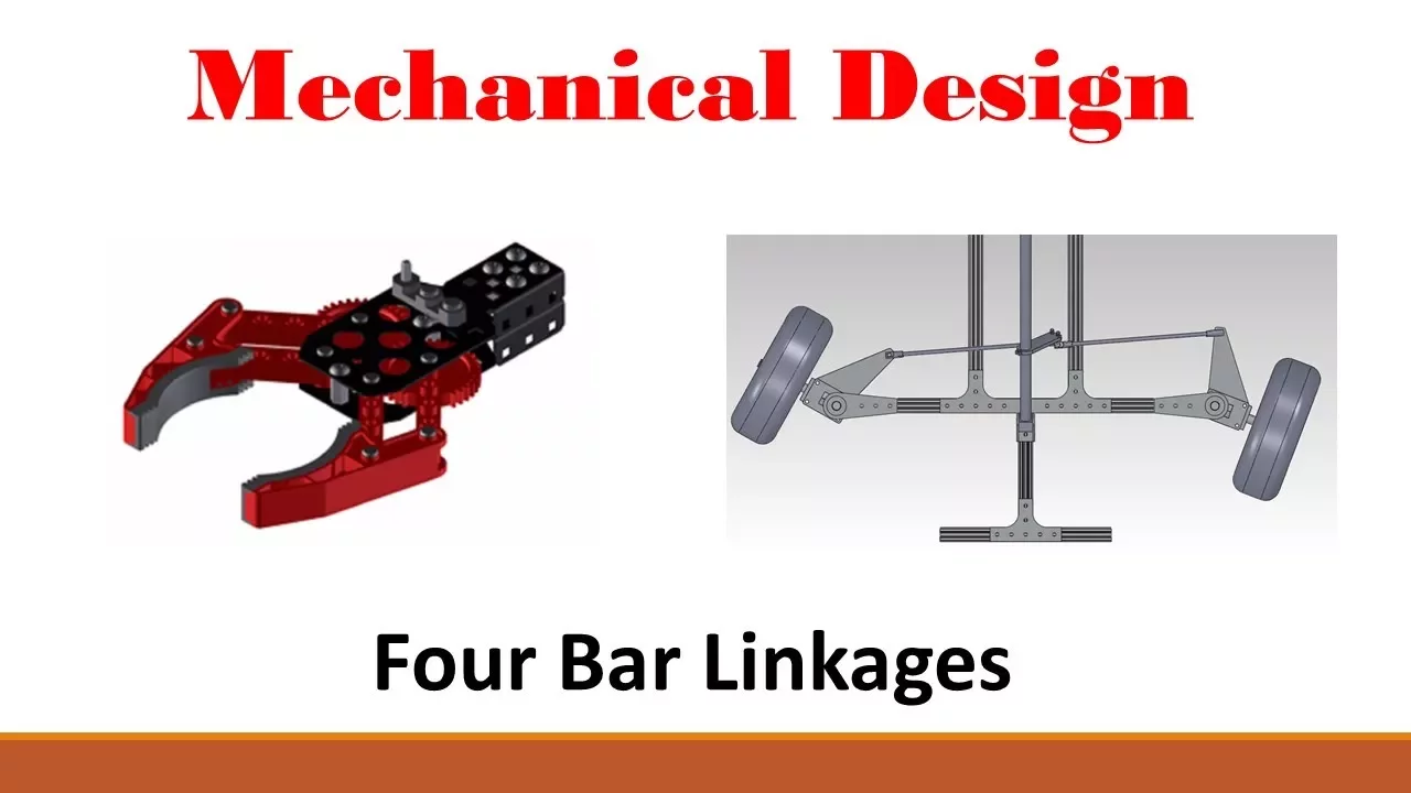
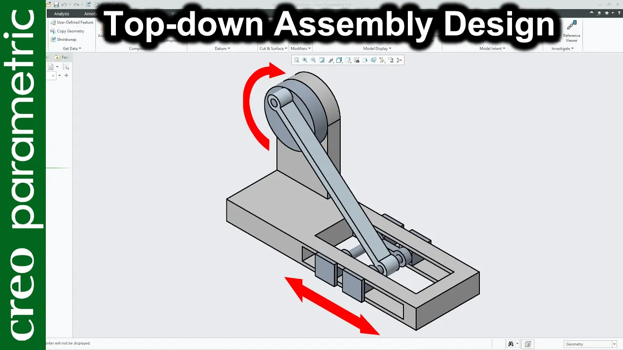
The Chebyshev Lambda linkage is a four-bar mechanism that converts rotational motion into approximately straight-line motion; it is a cognate (geometric variant) of the Chebyshev linkage that achieves similar output with different proportions, making it useful for applications like walking machines (plantigrade machines).
Creo Parametric: Chebyshev Lambda Linkage Mechanism Tutorial
Added:Basic proficiency in PTC Creo Parametric, including 3D part modeling, sketching, and standard assembly constraints.
Fundamentals of planar kinematics, specifically the concept of four-bar linkages, pin joints, and degrees of freedom.
Theoretical understanding of approximate straight-line mechanisms and how Chebyshev's Lambda linkage mathematically converts rotational motion to linear path segments.
Familiarity with the Creo Mechanism Design Extension (MDX) interface, including defining connections (pin joints) and applying servo motors.
Advanced kinematic synthesis and optimization of linkage dimensions to minimize deviation from a perfect straight-line path.
Dynamic simulation in Creo Parametric, analyzing joint reaction forces, motor torque requirements, and mass inertia effects.
Application of the Lambda linkage in multi-legged walking machine designs, such as the Chebyshev's Plantigrade Machine or Jansen's Linkages.
Physical prototyping of the linkage using 3D printing or laser cutting, factoring in real-world tolerances, joint friction, and backlash.
Exploring cognate linkages (using Roberts-Chebyshev theorem) to design alternative mechanisms that produce identical coupler curves.
9K views110likes16:22Original Release: 2022-10-12
in another video I showed how to create a Schmidt coupling from the popular YouTube video 20 mechanical principles combined in a useless Lego machine in this video I'm going to make another mechanism from that video the chabashev Lambda linkage and if I mispronounce that I'm sorry I'm probably going to mispronounce it throughout this video so I'm just going to call this the Lambda linkage it's called the Lambda linkage because it sort of looks like the Greek letter Lambda and this is what's called a cognate of the chabai shaft linkage which means that it creates the same output as the chibai chef linkage but it has different geometry and with this linkage it converts rotational motion into straight line motion and in another video I'm going to show how to create a plant-grade machine which is a walking machine it's really really neat but anyhow let me show you how this Lambda linkage works I've already set it up I'm going to show you how to create it on your own from scratch but let me show you the motion I'm going to just run this one and you can see how it moves around on here and you can't really get that it converted rotational motion into straight line motion so I'm going to use a trace curve in order to show that to you if I go to the analysis drop down menu in mechanism mode and then choose Trace curve I can choose to create a curve in a part I'll select this part for the one that will get the curve and then I will choose this point I'll do 2D let's select my result set and then click the OK button and so there you see the motion of the end of the fourth linkage in this Lambda machine and so it's got a curved portion but then it's got a relatively straight line portion now it's not perfectly straight but it's pretty darn close and that's why this linkage can be used in a lot of different machines so let me show you how to create this on your own I'm going to start off by creating a part that's going to be the basis for the linkage so let me go to the new button and I'm going to create a part and I'm going to call this my Lambda generic yes I'm going to make a family table in this video so let's click the OK button and let me turn on my plane display I'm going to sketch on the datum plane called front and for my shape let me look straight on at my sketch plane I'm going to create two circles let me create one about over here and one about over here and I let them snap to having the same diameter let me throw in a Center Line because I want to control the distance between the two centers let me put in a symmetric constraint so let me choose that and that and you'll notice that one of my weak Dimensions went away let's create a dimension from the center here to this one over here and then middle Mouse button and you want to choose your initial Dimension carefully because the other linkages are going to have lengths that are going to be a multiple of this one let me choose for this one I'll choose 100 to keep it nice and simple let me unclutter the screen by turning off the display of my planes for a moment let's change this diameter to a value of 20 and then I'm just going to create a couple of lines tangent between the circles this is going to be the basic shape for my linkage there we go and that looks good for my basic sketch let's hit the check mark to get out of sketch mode and I'm going to use a sketch region I did not use my friend squiggle Trim in order to get rid of the lines that you normally would get rid of with a traditional sketch but let's extrude this and I'm going to change the depth to symmetric and depth of I don't know 10 is good so that is my basic shape let me hit the check mark and turn on my datum axis display and for one of the linkages I'm going to need a hole in the center so let's create an axis for that one let me hit the axis icon and let's select This Plane hold down the control key and select this plane and I really don't need to rename this but let's do it anyway Center axis and hit the enter key so it accepts the name and now let's turn off our plane display and create some holes let me hide that sketch for some reason when you use sketch regions it does not hide the sketch one you create a true based off of it I guess it assumes that you want to create other features based off of these sketch regions so anyhow let's create a hole and I'll create it located on this axis let me hold down the control key and select a face and let's make this to next for the depth I'll take that diameter value that is fine and let's do that a couple more times let's do it for this one over here and to next I could have copied and pasted but in this particular situation it ends up being just about the same and two next and that is good all right and in three of the linkages I'm not going to need that Center hole so I'm going to rename this so let's call the center hole and for my Trace curve that I'm going to create later on I need to have a point in here let's create a new point and I'll create it at the intersection of let's say that axis hold down control key and select that face that is fine let me rename this and I'm going to call it Trace I like to rename my features especially if I'm going to use them in a family table so that is good for my generic now let's create a family table for the four different linkages I'll go to the model intent overflow menu and choose Family Table and now I will use this icon to choose what I want to vary in the feature let me pick the sketch out of the model tree just so I can get this length Dimension oops I should have renamed the length Dimension but I forgot that is okay I can always do that later on and then for features let's select the center hole and the point feature and then done and okay so those are the three things I'm going to vary in my family table let's create the different instances I need four of them I always like to create a separate instance so I'm not using the generic but let's call the first one this is going to be the ground and then let's call this one Lambda a and B and C and so the only one that needs the Center hole is going to be C so let's go to this and choose no no I really don't need to do this but hey I'm here might as well all right fill that in and I could leave the asterisks here I know that some people are like oh no you should never leave asterisk you want to control directly whether the features appear or not in the instance now let's change the lengths of them so for the ground this is going to have a length of 100 so we'll just leave it the same value now oh actually that's wrong the ground is going to need to be let's see twice the length of the shortest linkage let me change that to 200 and the shortest linkage is going to be a value of 100 the intermediate length linkage that's going to be a value of two and a half times the shortest length so let's plug in 250 for that one and then for the long linkage the one that's going to have the center hole let's change that to a value of 500 so it's going to be 5 times the shortest length and let me delete that row accidentally hit the enter key so that's good let me verify my family table hey yeah they were all a success let's click the OK button and now I'm going to hit the save button just so that I'm going to have all those different instances available to me when I hit the assemble button I could retrieve them from in session but might as well retrieve them from my working directory so anyhow I have my linkages created let's make our assembly and let's change the radio button to assembly I'll just call this my Lambda linkage so I don't butcher that old mathematician's name and then I will click the OK button so now we have our assembly started off let's hit the assemble button and I'm going to grab the Lambda ground and I can right Mouse click and hold and use the default constraint to locate it at the origin then I'll use the middle Mouse button to close the dashboard let's assemble linkage a here's Lambda a and I'll just grab it and we can rotate it and just move it a little closer to where I want it to be and this is going to have a pin connection let me use the connection type drop down list to change to pin and I will select this hole and then this hole over here and then to illuminate translation I'll pick this surface and then I'll tap the right Mouse button to query select to the back surface that's good and just so that this always goes back to the same configuration whenever I regenerate let's define our zero references so I want to control the angle between this surface and that surface let's change this to a value of 90 and then let's make this regeneration value and enable the Regeneration value I just always want it to be in the same configuration whenever I regenerate so that's good for that one let's turn off the axis display for a moment and now let's bring in the second linkage let's hit the assemble button and grab Lambda B and this one will have a pin connection just like the other one so let's go to pin and then pick the cylindrical surface cylindrical surface and let me grab a flat surface query select to the flat surface so that one is good as well and then hit the check mark and for the fourth linkage in my four bar linkage let's hit the assemble button once more and we'll grab the C linkage and let's just move it over a little bit and so this will have a pin connection on one end let's go to pin and I will choose that cylindrical surface and that one and sorry if I'm moving my model around on the screen too much let's pick the flat surfaces to eliminate translation so that's good for that one and let me just rotate it a little bit and now I'm going to add in a second connection for this component to have it connect to the hole in linkage B and for this one I could use a pin connection but I really don't need to eliminate translation for it since that is taken up by the first pin connection so I'll just use a cylinder connection and let me choose this cylindrical surface rotate a little bit out of the way and that one and the four bar linkage adjust so now I can hit the check mark to complete that and while I'm here I'm going to create one other part that's going to be empty uh and I'll use that for my Trace curve later on let's hit the create button and for the part I'll just call this the Lambda Trace hit the OK button and I'll use my standard template and then I'm just going to locate this at the default and hit the check mark So now I've got this empty part in here that I can use later on now let's jump into mechanism mode applications mechanism and let's throw in a motor I will select this axis to be driven and I can use the servo motor command from the mini toolbar I'm going to define the angular velocity and let's go to profile details I'll change this to 90 degrees per second and hit the check mark now I can Define the analysis let me click on analyzes in the mechanism tree here is the new icon and I will call this my Lambda I really like that word uh and let's do a kinematic analysis and since I did 90 degrees per second really only need four seconds for this to run and since I'm only doing four seconds let's crank up the frame rate and oh yeah I wanted to use the current configuration as a snapshot I forgot to create that let me click the OK button out of here for a moment and then I can go to drag components and let's hit the camera and I'm going to rename this let's call it start and then I can close out of here now let's expand analyzes in the mechanism tree edit to definition and I can specify that snapshot as what I want to use so that's good let's hit the Run button and you can see it move throughout here let's click OK and then underneath playbacks here is the result set I'm just going to left click on it and then hit the save button and then I'll save this and I'll just leave the default name that's good now in order to create that Trace curve to see the motion once again I will go to the analysis drop down menu Trace curve and for the paper part I will put that empty part that I created let's pick that datum Point as the one that I want to use I'll just leave it as 2D since this is 2D and then select my result set and click OK and so now we have the curve in the trace part that shows the motion that we got in our chibai Chev Lambda linkage so I hope you enjoyed this video and hey give it a shot yourself this is really really easy to make and fun and again later on we're going to make a wall Talking Machine known as a plantagrade machine
Up Next
24:28
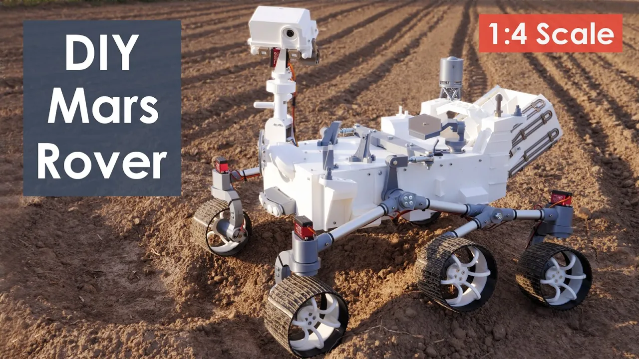
How I Built an Arduino Mars Rover Replica: Full Guide
@HowToMechatronics
565.3K views•2021-06-03

30:32
Ultrasonic Transducers: Resonant Frequency Measurement and Horn Design
@imajeenyus42
229.9K views•2017-02-22

54:16
Polymer Environmental Degradation: Mechanisms & Stabilization
@iit
1.8K views•2012-07-10

33:39
How a Student's Question Saved a NYC Skyscraper from Collapse
@veritasium
22.8M views•2025-04-26
Related Study Plans & Knowledge Roadmaps
Structured learning paths in Engineering
engineering
Building Acoustic Levitators: Physics & Arduino
01The Physics of Sound and Standing Waves
02Piezoelectric Transducers and H-Bridge Drivers
03Arduino Programming: Generating 40 kHz Signals
+ 2 more learning modules
14h5 modules
Explore Roadmap
engineering
Building Peltier Cloud Chambers: Particle Tracks
01Cosmic Rays & Cloud Chamber Physics
02Thermoelectric Cooling (TEC) Fundamentals
03Custom Liquid-Cooling Loop Design
+ 2 more learning modules
18h5 modules
Explore Roadmap
engineering
Yagi-Uda Antennas: Modeling, Build & VNA Test
01Introduction to RF and Antenna Fundamentals
02Yagi-Uda Antenna Design Principles
03Antenna Modeling and Simulation in 4NEC2
+ 2 more learning modules
18h5 modules
Explore Roadmap
engineering
ECG Monitor Design: Op-Amps, Filters & Noise
01Electronics & Breadboard Basics
02Op-Amps and Instrumentation Amplifiers
03Bioelectricity and ECG Fundamentals
+ 2 more learning modules
18h5 modules
Explore Roadmap