A vapour compression refrigeration system is a cyclic process that cools an enclosed space by repeatedly compressing, condensing, expanding, and evaporating a refrigerant; the four main components work together where the compressor increases pressure and temperature, the condenser transfers heat to the surroundings, the expansion valve reduces pressure and temperature, and the evaporator absorbs heat from the space to be cooled.
Vapor Compression Refrigeration System Explained with Animation
Added:Deep Dive
Basic laws of thermodynamics, particularly heat transfer principles and how heat naturally flows from warmer to cooler regions.

Basics of Heat Transfer- Heat and Mass Transfer
1.3K
The first law of thermodynamics states that the rate of energy transfer into a system equals the rate of increase of energy of the system. The second law requires that heat transfer occurs in the direction of decreasing temperature, meaning heat naturally flows from higher temperature to lower temperature regions.
Click to watch →

Heat Transfer | Introduction | ME CH GATE 2022| ESE 2021| Sandeep sir
49.4K
The First Law of Thermodynamics states that energy cannot be created or destroyed, only converted from one form to another. The Second Law of Thermodynamics states that heat naturally flows from higher temperature to lower temperature, determining the direction of spontaneous processes. These laws form the foundation for understanding heat transfer behavior. The temperature difference is the fundamental driving force for all modes of heat transfer, and without it, no heat transfer will occur regardless of the mode.
Click to watch →

General Science | Important Pyqs | For Jkssb Laboratory Attendant | Fpf | wildlife | All other Exams
6.6K
Heat transfer occurs according to the Second Law of Thermodynamics, which states that heat naturally flows from a hot body to a cold body. This law explains why heat transfer always occurs from higher to lower temperature regions and never spontaneously in the reverse direction.
Click to watch →

ऊष्मागतिकी - 1 | Thermodynamics | Chapter 6 | Chemistry Class 11 | Origin Coaching
131.4K
Heat flows from higher temperature to lower temperature, similar to liquid flowing from higher to lower volume. When two objects at different temperatures contact, heat transfers until thermal equilibrium is reached. Joule discovered heat is not a substance but a form of energy. The laws of thermodynamics establish that heat (energy) always flows from hotter to colder bodies until temperatures equalize.
Click to watch →

1st Law of Thermo-Dynamics + Q&A | Thermo-Dynamics (L-3) | 11th CBSE NEET | Arvind Arora
187.1K
Heat is the mode of energy transfer due to temperature difference between a system and its surroundings. Heat always flows from higher temperature to lower temperature regions. When a system is at a lower temperature than its surroundings, heat transfers from surroundings to the system. Conversely, when the system is at a higher temperature, heat transfers from the system to the surroundings. This directional flow continues until thermal equilibrium is reached.
Click to watch →
Deep Dive
The concept of latent heat and phase changes, specifically how substances absorb heat when evaporating and release heat when condensing.

【2027共通テスト完全対応】4時間で極める地学基礎 無料テキスト付き!!
39.4K
Phase changes involve the absorption or release of latent heat: (1) Melting (solid to liquid) absorbs heat; (2) Freezing (liquid to solid) releases heat; (3) Vaporization (liquid to gas) absorbs heat; (4) Condensation (gas to liquid) releases heat; (5) Sublimation (solid to gas) absorbs heat; (6) Deposition (gas to solid) releases heat. Latent heat is the energy absorbed or released during phase changes without a change in temperature. This concept is important for understanding weather patterns, as phase changes of water release or absorb large amounts of energy that drive atmospheric circulation.
Click to watch →

IAS 2021 | Gurukul 2.0 | Geography by Sumit Rathi | Temperature| Part 2
32.9K
Latent heat is energy absorbed or released during phase changes without temperature change. Latent heat of vaporization is energy absorbed when liquid changes to gas, causing cooling. Latent heat of condensation is energy released when gas changes to liquid, causing warming. During evaporation, substances absorb energy from surroundings, which is why evaporation causes cooling. During condensation, substances release energy to surroundings, which is why condensation causes warming.
Click to watch →
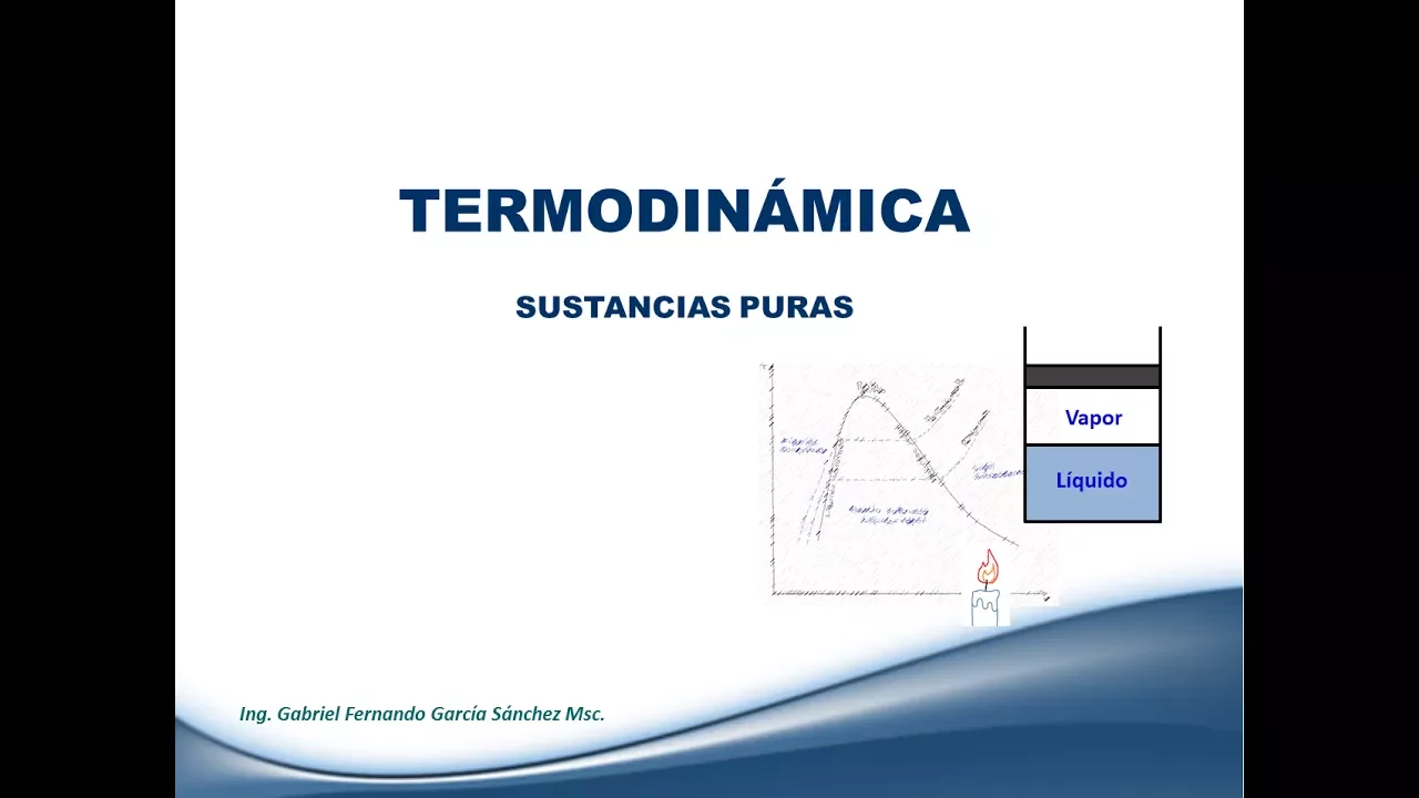
Sustancias puras - Clase 5 Termodinámica
123.5K
Latent heat is the amount of energy absorbed or released during a phase change without temperature change. When a substance absorbs latent heat, it undergoes transformation: solid to liquid (melting/fusion) or liquid to gas (vaporization/evaporation). Conversely, when releasing latent heat, the substance changes from gas to liquid (condensation) or liquid to solid (freezing). For example, ice absorbs heat to melt into water, and boiling water absorbs heat to become steam.
Click to watch →

Lecture 37 Geography by Ajit Sir, 72 BPSC
178
Latent heat (also called hidden heat) is the energy absorbed or released during a phase change of matter without changing its temperature. For example, when liquid water evaporates into vapor, it absorbs latent heat from its surroundings without increasing in temperature. Similarly, when water vapor condenses back into liquid, it releases latent heat. This explains why 100°C steam is more dangerous than 100°C liquid water—the steam contains additional latent heat energy.
Click to watch →

Кузнецов Сергей Владимирович, Общая физика: термодинамика, Лекция 11
291
Latent heat is the heat absorbed or released during a phase transition at constant temperature. For gas-liquid transitions, latent heat is absorbed when liquid evaporates (molecules gain energy to escape) and released when gas condenses (molecules lose energy when forming bonds). The latent heat equals the temperature times the entropy change: L = TΔS.
Click to watch →
Deep Dive
The relationship between pressure and temperature in fluids, including how changing pressure alters the boiling point of a substance.

#03 Reversible & Irreversible Process | Engg.Thermodynamics | Crash Course (English) | Varun Sir
3.6K
The boiling point temperature is a function of pressure. Even a slight change in pressure causes changes in the boiling point temperature. When pressure increases, more energy must be provided to separate molecules, resulting in an increase in boiling point temperature. This relationship is fundamental to understanding phase transitions and thermodynamic systems.
Click to watch →

Relationship between External Pressure and #BoilingPoint | Effect on boiling point change Pressure
135
There is a direct relationship between pressure and boiling point: as pressure increases, the boiling point increases, and as pressure decreases, the boiling point decreases. This relationship occurs because boiling requires the liquid's vapor pressure to equal the external pressure. Higher external pressure requires the liquid to reach a higher temperature to generate sufficient vapor pressure to match it.
Click to watch →

PROPERTIES OF PURE SUBSTANCES
419
There is a direct relationship between pressure and boiling point temperature. As pressure increases, the boiling point temperature increases, and as pressure decreases, the boiling point temperature decreases. This relationship is fundamental to understanding phase transitions and is why water boils at different temperatures at different altitudes or pressures. The boiling point is not a fixed value but depends on the surrounding pressure conditions.
Click to watch →

Effect of Pressure on Melting Point | Regelation | Chapter 10 | Thermal Properties of matter | 11
13K
Boiling point is directly proportional to pressure for all substances. When pressure increases, boiling point increases; when pressure decreases, boiling point decreases. This occurs because the vapor phase always has lower density than the liquid phase. Increasing pressure prevents the expansion needed for vaporization, requiring more heat energy to achieve boiling. Conversely, decreasing pressure allows easier expansion, lowering the boiling point. This principle explains why pressure cookers cook food faster (water boils at ~121°C instead of 100°C) and why food cooks differently at high altitudes (lower pressure → lower boiling point).
Click to watch →

Complete Physics Rapid Revision | Complete Physics | 71st BPSC Prelims 2025 | @YouTube
43.9K
The boiling point of a liquid increases with increasing pressure and decreases with decreasing pressure. At standard atmospheric pressure (1 atm), water boils at 100°C. In a pressure cooker, higher pressure raises the boiling point above 100°C, allowing food to cook faster. At high altitudes, lower pressure lowers the boiling point.
Click to watch →
Deep Dive
The definition and general properties of a refrigerant as a thermodynamic working fluid.
Properties of Refrigerants || Thermodynamic Properties || Chemical Properties || Physical properties
304
Thermodynamic properties define a refrigerant's ability to perform its primary function of absorbing heat at low temperature and rejecting it at higher temperatures. Key properties include: Critical temperature (should be as high as possible to ensure condensation occurs under normal operating conditions); Enthalpy of vaporization (should be large to maximize heat absorption capacity); Thermal conductivity (should be high for efficient heat transfer); Coefficient of Performance (COP, should be large to minimize operating costs); Specific heat (liquid phase should be small, vapor phase should be large); Pressure ratio (should be minimized to reduce work input and maintain refrigeration effect); Freezing point (should be as low as possible to prevent solidification during operation); Specific volume at compressor inlet (should be small to reduce compression work); Compressor discharge temperature (should not be excessively high to avoid excessive work and heat removal requirements); and Boiling point (should be low to enable easy evaporation with minimal heat addition).
Click to watch →

Refrigerants and their desirable projects
936
A refrigerant is a working fluid used in refrigeration and air conditioning systems that undergoes repeated phase transitions from liquid to vapor and back. Common refrigerants include ammonia, carbon dioxide, sulfur dioxide, methyl chloride, Freon-12, and Freon-22. Good refrigerants must have specific thermodynamic properties: low boiling point at atmospheric pressure, very low freezing point to prevent freezing during operation, and operating pressures slightly above atmospheric pressure to prevent air leakage and enable leak detection. Additionally, high latent heat of vaporization increases refrigeration efficiency by allowing smaller amounts of refrigerant to accomplish desired cooling effects, while low specific volume reduces compressor size and system compactness.
Click to watch →

Refrigeration || What is Refrigerating Effect || What is Refrigerant || RAC
310
A refrigerant is the working substance that flows through a refrigerator to carry heat. It is also called the working fluid used in the refrigeration cycle. A refrigerant absorbs heat through expansion or vaporization and rejects that heat through condensation in a refrigeration system.
Click to watch →

RAC| G3 Batch | Day-1 Bteup Exam 2024 | Polytechnic 4th Semester @gtechpoly
41.2K
A refrigerant is a working fluid that absorbs heat through vaporization and releases heat through condensation. Desired properties include: (1) Thermodynamic: Low freezing/boiling point, high latent heat, high critical temperature, (2) Chemical: Non-toxic, non-corrosive, non-flammable, chemically stable, (3) Physical: Low viscosity, high thermal conductivity, low specific volume, high electrical conductivity, (4) Practical: Easy leak detection, readily available, low cost, inert and miscible with oil, low pressure ratio. Refrigerants are classified into: (1) Primary Refrigerants - directly participate in refrigeration system (ammonia, freon R12, carbon dioxide), (2) Secondary Refrigerants - first cooled by primary refrigerants then used for cooling (water, brine solutions). Primary refrigerants are further classified into: (1) Halocarbon Refrigerants - compounds containing halogens and carbon (methyl chloride), (2) Azeotropic Refrigerants - mixtures that cannot be separated by distillation, (3) Inorganic Refrigerants - ammonia, carbon dioxide, (4) Hydrocarbon Refrigerants - methane, ethane, propane, butane.
Click to watch →
Desirable Properties of refrigerant II Ideal refrigerant II RAC
787
Refrigerants are working fluids used in refrigeration systems like refrigerators and air conditioners, classified into groups based on chemical composition (Group 2: Dichlorodifluoromethane, Dichlorotrifluoroethane; Group 11: CO2). Thermodynamic properties include: (1) Low boiling point (negative temperature, e.g., ammonia at -33.34°C) for effective heat absorption; (2) High latent heat of vaporization for maximum cooling capacity; (3) Critical temperature as the maximum temperature for condensation to occur. These properties determine the refrigerant's effectiveness in the refrigeration cycle.
Click to watch →
Prerequisite Knowledge
- Concept 01Basic laws of thermodynamics, particularly heat transfer principles and how heat naturally flows from warmer to cooler regions.
- Concept 02The concept of latent heat and phase changes, specifically how substances absorb heat when evaporating and release heat when condensing.
- Concept 03The relationship between pressure and temperature in fluids, including how changing pressure alters the boiling point of a substance.
- Concept 04The definition and general properties of a refrigerant as a thermodynamic working fluid.
Subsequent Learning
- Step 01Analysis of the refrigeration cycle using thermodynamic diagrams, specifically Pressure-Enthalpy (P-h) and Temperature-Entropy (T-s) charts.
- Step 02Calculating the Coefficient of Performance (COP) to measure the energy efficiency of the refrigeration system.
- Step 03The concepts of superheating and subcooling, and how they are applied in real-world HVAC systems to optimize performance and protect the compressor.
- Step 04Environmental impacts of various refrigerant types, including their Global Warming Potential (GWP) and Ozone Depletion Potential (ODP).
- Step 05Alternative cooling technologies, such as Vapor Absorption Refrigeration Systems (VARS) and thermoelectric cooling.
VCRS Basics
Cycle Work
VCRS Basics
0:00Playing Section
- 1
Defines refrigeration as heat removal from a closed space.
- 2
Identifies four core components: evaporator, compressor, condenser, expansion valve.
Absorption and Solid-State Refrigeration Technologies
While Vapor Compression Refrigeration Systems (VCRS) are the industry standard, they are criticized for high electrical consumption, mechanical wear, and reliance on environmentally harmful synthetic refrigerants. Key alternatives include Absorption Refrigeration Systems (ARS) and Solid-State Cooling (Thermoelectric and Magnetic). ARS replaces the energy-intensive mechanical compressor with a thermal process, often utilizing waste heat or solar energy. Solid-state technologies eliminate both chemical refrigerants and moving parts entirely, using instead electric currents or magnetic fields to transfer heat. These alternatives provide quieter, low-maintenance, and eco-friendly cooling solutions, challenging the dominance of traditional vapor compression.
Deep Dive
Analysis of the refrigeration cycle using thermodynamic diagrams, specifically Pressure-Enthalpy (P-h) and Temperature-Entropy (T-s) charts.
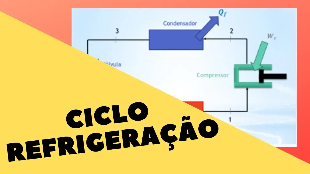
Ciclo de Refrigeração | Termodinâmica
63K
The refrigeration cycle is the inverse of the Rankine cycle, using energy to remove heat from a source rather than producing energy. It operates between high pressure P2 and low pressure P1, consisting of four components: evaporator (absorbs heat and causes evaporation), compressor (adds work and increases pressure), condenser (removes heat and condenses vapor to liquid), and expansion valve (reduces pressure and increases specific volume). The cycle is analyzed using a Temperature-Entropy (T-S) diagram. The compressor process is isentropic, producing superheated vapor. Condensation occurs at constant high pressure, transforming fluid to saturated liquid. The expansion valve process is isentropic, reducing pressure and creating a liquid-vapor mixture. The evaporation process occurs at constant low pressure, absorbing heat and returning to saturated vapor state.
Click to watch →
RAC| G3 Batch | Day-1 Bteup Exam 2024 | Polytechnic 4th Semester @gtechpoly
41.2K
The P-H (Pressure-Enthalpy) and T-S (Temperature-Entropy) diagrams are used to analyze the Vapor Compression Refrigeration System. In the P-H diagram: (1-2) Isentropic compression, (2-3) Constant pressure heat rejection, (3-4) Isenthalpic expansion, (4-1) Constant pressure heat absorption. In the T-S diagram: (1-2) Isentropic compression, (2-3) Constant pressure heat rejection, (3-4) Isenthalpic expansion, (4-1) Constant pressure heat absorption. These diagrams help visualize the thermodynamic processes and calculate system performance.
Click to watch →

Refrigeration - Schematic and a Pressure Enthalpy Chart
231.6K
A pressure-enthalpy (p-h) diagram is used to analyze refrigeration cycles. On this diagram, pressure is plotted on the Y-axis and enthalpy on the X-axis. The diagram features a bell-shaped curve skewed to the right, representing the saturation region where liquid and vapor coexist. The ideal refrigeration cycle is drawn by connecting specific points: starting with a horizontal line from within the bell curve to the saturated vapor curve, then following a constant entropy curve (isentropic process), drawing a horizontal line at high pressure until meeting the saturated liquid curve, and finally dropping a vertical line to complete the cycle.
Click to watch →

Vapour Compression Refrigeration Cycle in Hindi, Diagram, Processes, TS, Ph Diagram, COP VCRS Cycle
73.3K
The T-S (Temperature-Entropy) and P-H (Pressure-Enthalpy) diagrams are essential tools for analyzing the vapour compression cycle. In the T-S diagram, compression (1-2) is isentropic with constant entropy, condensation (2-3) shows constant pressure heat rejection with temperature decrease, throttling (3-4) is irreversible with entropy increase, and evaporation (4-1) is constant pressure heat absorption. In the P-H diagram, compression increases enthalpy, condensation decreases enthalpy at constant pressure, throttling maintains constant enthalpy with entropy increase, and evaporation increases enthalpy. These diagrams help visualize the thermodynamic states and energy transfers throughout the cycle.
Click to watch →

🥶 CICLO DE REFRIGERACIÓN POR COMPRESIÓN DE VAPOR | Diagramas T-s y P-h ❄
6.8K
Two primary diagrams visualize refrigeration cycles: Temperature-Entropy (T-s) and Pressure-Enthalpy (P-h) diagrams. The T-s diagram shows saturation dome boundaries (saturated liquid/vapor lines), with isentropic compression (constant entropy), constant-pressure condensation (decreasing temperature), throttling (horizontal line), and constant-pressure evaporation. The P-h diagram plots pressure versus enthalpy, displaying similar processes but emphasizing enthalpy changes. Both diagrams represent identical physical processes, with P-h being particularly useful for calculating work and heat transfers. Understanding these diagrams enables visualization of cycle performance, identification of inefficiencies, and optimization of refrigeration system design.
Click to watch →
Deep Dive
Calculating the Coefficient of Performance (COP) to measure the energy efficiency of the refrigeration system.

KTU & CUSAT B.TECH LET 2023 MECHANICAL ENGINEERING I MODULE 1I MCQ I PART 1
2.1K
The Coefficient of Performance (COP) measures refrigerator efficiency as the ratio of refrigeration effect to work input. For a system with 130 kJ/kg refrigeration effect and 40 kJ/kg work input, COP = 3.25. COP efficiency is calculated as actual COP divided by theoretical COP. For a system with 250 kJ/kg refrigeration effect and 100 kJ/kg work input, actual COP = 2.5. If theoretical COP is 3.83, efficiency = 2.5/3.83 ≈ 0.653 (65.3%).
Click to watch →
Co-efficient of Performance || COP || COP of Refrigerator || What is COP || COP of ref.
339
The Coefficient of Performance (COP) is a dimensionless measure of the efficiency of a refrigerator or refrigeration system, defined as the ratio of the refrigerating effect (heat extracted from the evaporator) to the work input required to compress the refrigerant. Mathematically, COP equals Q/W, where Q represents the heat absorbed by the refrigerant in kilojoules per minute, and W represents the work input to the compressor in kilojoules per minute. This metric quantifies how effectively a refrigeration system converts work input into cooling capacity, with higher COP values indicating greater efficiency.
Click to watch →
Refrigeration & air conditioning plant Lab experiment(quickly!)🔥
18.5K
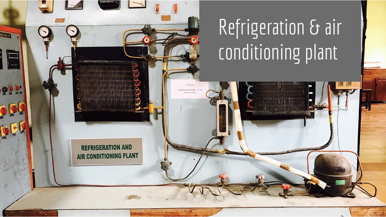
The Coefficient of Performance (COP) measures the efficiency of a refrigeration system and is calculated as the ratio of the refrigerating effect to the work input. The refrigerating effect equals h1 - h4 (enthalpy difference between evaporator outlet and inlet). The work input equals h2 - h1 (enthalpy difference between compressor outlet and inlet). Therefore, COP = (h1 - h4) / (h2 - h1). Higher COP values indicate more efficient systems.
Click to watch →

Refrigerators
117
The Coefficient of Performance (COP) measures refrigeration system efficiency as the ratio of cooling effect to compressor work input. In the example, with 50 kW cooling effect and 11.5 kW compressor work, COP equals approximately 4.4. Since COP > 1, the system is efficient. COP calculation involves enthalpy differences: COP = (h2 - h1) / (h2 - h3), where h1, h2, h3 are enthalpy values at different cycle points. Higher COP indicates better system efficiency.
Click to watch →

Power Engineering Revision Part 2 | PER IMP Question | Power Engineering IMP | Vineet Tutorials
7K
Coefficient of Performance (COP) measures refrigeration system efficiency as the ratio of refrigerating effect to work input. COP = Refrigerating Effect / Work Input. Higher COP indicates better efficiency and lower running costs. COP is inversely proportional to work input: as COP increases, required work input decreases. This relationship is crucial for comparing different refrigeration systems and understanding energy consumption. COP has no units and is a dimensionless quantity representing system performance.
Click to watch →
Deep Dive
The concepts of superheating and subcooling, and how they are applied in real-world HVAC systems to optimize performance and protect the compressor.

What is Superheat and Subcooling | Animation |#superheat #subcooling #hvac #chiller #thermodynamics
218.3K
Superheat is the temperature rise of a refrigerant above its saturation temperature during evaporation, ensuring only vapor enters the compressor (since liquid cannot be compressed); subcooling is the temperature reduction of a refrigerant below its saturation temperature during condensation, ensuring complete liquid formation before reaching the expansion valve. Both parameters are critical for proper HVAC system operation and compressor protection.
Click to watch →
Subcooling and Superheat Explained
28.5K
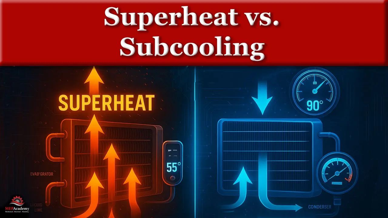
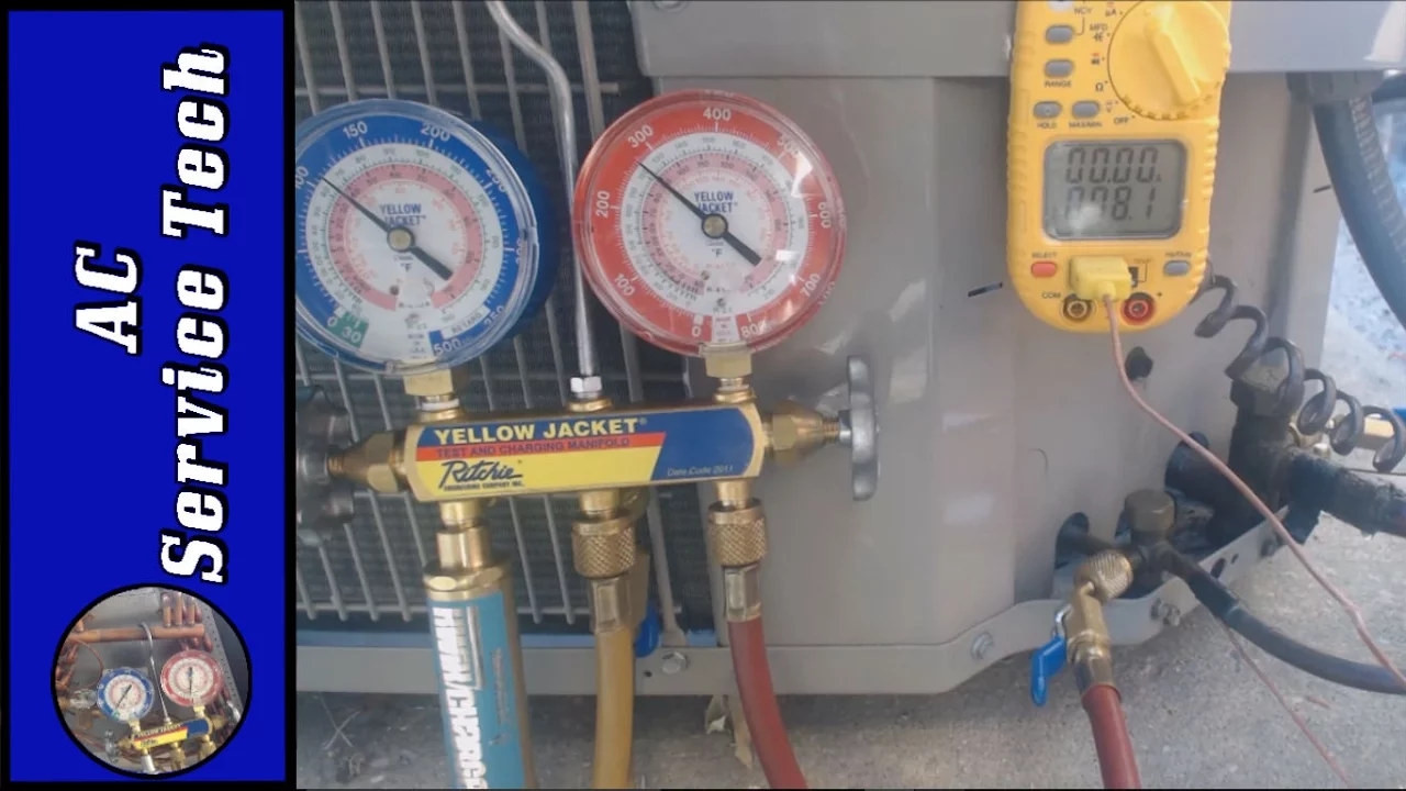
Superheat measures the temperature of vapor refrigerant above its boiling point at a given pressure, indicating how much heat the refrigerant has absorbed after boiling in the evaporator; it is measured at the suction line before the compressor to ensure only vapor enters and protects the compressor from liquid slugging. Subcooling measures the temperature of liquid refrigerant below its condensing point at a given pressure, indicating how much the refrigerant has been cooled after fully condensing in the condenser; it is measured at the liquid line before the metering device to ensure only liquid enters and protects against flash gas. Proper superheat (typically 10-20°F) prevents compressor damage from liquid refrigerant, while proper subcooling (typically 8-15°F) prevents metering device issues and ensures optimal system charging.
Click to watch →
SUPERHEAT And SUBCOOLING Explained (HVAC 101) Simple & Easy
42.3K
Superheat is the temperature above a refrigerant's saturation (boiling) temperature, typically measured on the suction line leaving the evaporator and discharge line leaving the compressor; subcooling is the temperature below the saturation temperature, measured on the liquid line after refrigerant leaves the condenser. Both concepts represent the temperature difference between the actual refrigerant temperature and its saturation temperature at a given pressure, indicating how much the refrigerant has deviated from its phase-change state.
Click to watch →

Saturation, Superheat, Subcooling
221.2K
In refrigeration systems, saturation is the fundamental relationship where pressure (PSIG) converts to a specific temperature (saturation temperature), representing the boiling point where liquid and vapor coexist in equilibrium; superheat is the sensible heat added to vapor above its saturation point, ensuring only vapor enters the compressor and preventing liquid slugging; and subcooling is the sensible heat removed from liquid below its saturation point, ensuring liquid refrigerant reaches the metering device without flashing. These three concepts—saturation (change of state), superheat (vapor above saturation), and subcooling (liquid below saturation)—are essential for diagnosing and maintaining HVAC systems, with the key principle being that anything above saturation is superheated vapor and anything below saturation is subcooled liquid.
Click to watch →
Exactly What is Superheat and Subcooling? Shown on a Live AC Unit!
277.7K
In HVAC systems, superheat and subcooling are critical parameters for determining proper refrigerant charge levels: subcooling is measured on the liquid line side of TXV systems by comparing liquid line temperature to the saturated temperature derived from high-side pressure (target typically 10°F), while superheat is measured on the vapor side of piston/capillary tube systems by comparing suction line temperature to the saturated temperature from low-side pressure combined with wet bulb temperature readings (target typically 8°F); both parameters must be checked when the system is under load and ambient temperature is around 70°F, with adjustments made by adding or removing refrigerant to bring values within acceptable ranges (±3°F).
Click to watch →
Deep Dive
Environmental impacts of various refrigerant types, including their Global Warming Potential (GWP) and Ozone Depletion Potential (ODP).

The TRUTH about the “new” refrigerants | R32 and R454B refrigerants phase in
174K
Refrigerants are evaluated using two key metrics: GWP (Global Warming Potential) and ODP (Ozone Depletion Potential). These are numerical ratings assigned by manufacturers that indicate the environmental impact of a refrigerant. A GWP rating of 100 means that 1 pound of refrigerant is equivalent to the atmospheric impact of 100 pounds of carbon dioxide. The EPA has mandated that refrigerants with GWP above 750 must be phased out, which is why R410A (with GWP over 2,000) will eventually be replaced despite having zero ODP.
Click to watch →
Webinar #1 - 04 de Agosto. Gases Refrigerantes Naturales vs HFC HCFC HFO (ACAIRE - INTARCON)
559
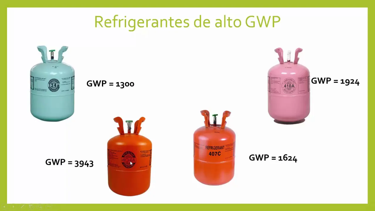
Environmental impact is measured by Ozone Depletion Potential (ODP) and Global Warming Potential (GWP). R-11 has ODP=1, R-22 has ODP=0.05. GWP values: R-134a=1300, R-22=1810, while natural refrigerants have GWP between 0-3. The Montreal Protocol phased out ozone-depleting substances, with HCFCs eliminated by 2030. Refrigerant nomenclature follows a code: R indicates refrigerant, first number = fluorine atoms, second number = hydrogen atoms +1, third number = carbon atoms -1, fourth number = double bonds.
Click to watch →

Ciclo Básico de Refrigeração e Compressores | Semana da Refrigeração Coel 2021
40K
Refrigerants have significant environmental impacts: ODP (Ozone Depletion Potential) measures ozone layer damage, GWP (Global Warming Potential) measures global warming impact. R12 has ODP of 1.0 and GWP of 10,900. R134A has ODP of 0.0 and GWP of 1,430. R404A has ODP of 0.0 and GWP of 3,922. R410A has ODP of 0.0 and GWP of 2,088. R600 has ODP of 0.0 and GWP of 3. Refrigerants are classified by safety characteristics: toxicity and flammability range from A1 (non-toxic, non-flammable) to B3 (toxic, flammable). A2L refrigerants are slightly flammable. Technicians must understand these classifications to work safely.
Click to watch →
REFRIGERANTES E INDICADORES AMBIENTALES QUE IDENTIFICAN SU IMPACTO AMBIENTAL
7.1K
Refrigerants are assessed for environmental impact using two key metrics: Ozone Depletion Potential (ODP) and Global Warming Potential (GWP). ODP measures a refrigerant's capacity to degrade the ozone layer, with values ranging from 0 (no degradation) to 1 (maximum degradation). GWP measures contribution to global warming, with CO2 as the baseline (GWP = 1). Ozone-depleting refrigerants like R-11, R-12, R-22, and R-141b have ODP values greater than 0 and are prohibited in many countries. Non-depleting alternatives like R-134a, R-410a, and hydrocarbons have ODP = 0. However, some non-depleting refrigerants still have high GWP values (R-404a: 3,943), indicating significant global warming impact.
Click to watch →

Gases Refrigerantes DUPONT en SENATI
11.7K
Refrigerants have different environmental impacts: (1) Ozone layer depletion - addressed by the Montreal Protocol through phase-out of CFCs and HCFCs; (2) Global warming potential (GWP) - addressed by newer refrigerants with lower GWP. R12 had a GWP of 10,000, while R134a has a GWP of 1,300 (90% reduction). The newer Ion refrigerants (MO49, MO29) have even lower GWP. Option (R1234yf) has a GWP of only 4-5 and a lifetime of only hours in the atmosphere. This distinction is important for understanding the full environmental impact of refrigerants.
Click to watch →
Deep Dive
Alternative cooling technologies, such as Vapor Absorption Refrigeration Systems (VARS) and thermoelectric cooling.
Refrigeration Cycles Quick revision For Mechanical SSC JE, UPPSC AE, NCL, NPCIL, UPSSSC
29.6K
The vapor absorption refrigeration system (VAR S) is an alternative to vapor compression refrigeration that eliminates the need for a mechanical compressor. In VARS, the compressor is replaced by an absorber, generator, and small pump. The system uses ammonia as the refrigerant and water as the absorbent. The main advantage is lower operating costs since the pump requires much less work than a compressor. The system can use waste heat or solar energy for power, making it suitable for applications where electricity is expensive or unavailable.
Click to watch →

SSC JE 2025 Mechanical Last 20 Days Crash Course | RAC | SSCJE Mechanical classes
16.4K
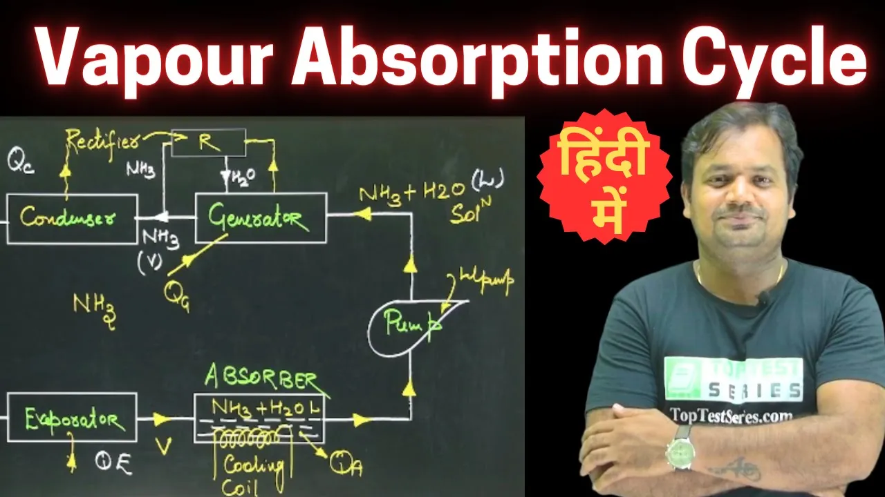
This section introduces the Vapour Absorption Refrigeration System (VARS). In VARS, the mechanical compressor is replaced by an absorber, pump, generator, rectifier, and heat exchanger. The basic components are: Evaporator, Absorber, Pump, Generator, Rectifier, Condenser, Expansion Valve, and Heat Exchanger. The arrangement is similar to VCRS but with absorption-based pressure reduction. The refrigerant is Ammonia (NH3) and the absorbent is Water (H2O). The solution in the absorber is called 'weak solution' (dilute ammonia-water mixture), while the solution in the generator is called 'strong solution' (concentrated ammonia-water mixture).
Click to watch →
Vapour Absorption Refrigeration System in Hindi - Working, COP, PV, TS Diagram
1.1K
Vapour Absorption Refrigeration System (VARS) is an alternative to Vapour Compression Refrigeration System. The key difference is that the compressor is replaced by three components: Absorber, Pump, and Generator. The system uses a refrigerant-absorbent pair (commonly NH3-H2O) to achieve continuous refrigeration through thermodynamic cycles. The working principle involves heat-driven processes rather than mechanical compression.
Click to watch →

ALP CBT 2 RAC Trade || 🚀RAC ALP CBT 2 || RRB ALP CBT 2 RAC Classes || RAC Classes For ALP CBT 2
1.7K
Liquid gas refrigeration uses the evaporation of liquefied gases like liquid nitrogen and liquid carbon dioxide for food preservation and industrial cooling. Vapor compression refrigeration is the most widely used system, consisting of an evaporator (heat absorption), compressor, condenser (heat release), and expansion valve. Vapor absorption refrigeration uses an absorber and generator instead of a compressor, using heat to separate refrigerant from working fluid. Thermoelectric refrigeration is based on the Peltier effect, where electrical current creates temperature differences at junctions of different metals, with no moving parts but limited cooling capacity.
Click to watch →
Vapor Absorption System and It's difference with Vapor Compression System | Explained in Bangla |
210
The Vapor Absorption Refrigeration System (VARS) is an alternative to the Vapor Compression Refrigeration System (VCRS). While both systems share common components like evaporator, condenser, and expansion valve, VARS replaces the compressor with three components: absorber, pump, and generator. The compressor performs three functions: sucking refrigerant from evaporator, increasing temperature and pressure, and delivering refrigerant to condenser. In VARS, these functions are distributed among the absorber, pump, and generator respectively. The system uses ammonia as refrigerant and water as absorbent, with ammonia circulating through the entire cycle while water only circulates between absorber and generator.
Click to watch →
VCRS Basics
Cycle Work
VCRS Basics
0:00- 1
Defines refrigeration as heat removal from a closed space.
- 2
Identifies four core components: evaporator, compressor, condenser, expansion valve.
Absorption and Solid-State Refrigeration Technologies
While Vapor Compression Refrigeration Systems (VCRS) are the industry standard, they are criticized for high electrical consumption, mechanical wear, and reliance on environmentally harmful synthetic refrigerants. Key alternatives include Absorption Refrigeration Systems (ARS) and Solid-State Cooling (Thermoelectric and Magnetic). ARS replaces the energy-intensive mechanical compressor with a thermal process, often utilizing waste heat or solar energy. Solid-state technologies eliminate both chemical refrigerants and moving parts entirely, using instead electric currents or magnetic fields to transfer heat. These alternatives provide quieter, low-maintenance, and eco-friendly cooling solutions, challenging the dominance of traditional vapor compression.
Basic laws of thermodynamics, particularly heat transfer principles and how heat naturally flows from warmer to cooler regions.
The concept of latent heat and phase changes, specifically how substances absorb heat when evaporating and release heat when condensing.
The relationship between pressure and temperature in fluids, including how changing pressure alters the boiling point of a substance.
The definition and general properties of a refrigerant as a thermodynamic working fluid.
Analysis of the refrigeration cycle using thermodynamic diagrams, specifically Pressure-Enthalpy (P-h) and Temperature-Entropy (T-s) charts.
Calculating the Coefficient of Performance (COP) to measure the energy efficiency of the refrigeration system.
The concepts of superheating and subcooling, and how they are applied in real-world HVAC systems to optimize performance and protect the compressor.
Environmental impacts of various refrigerant types, including their Global Warming Potential (GWP) and Ozone Depletion Potential (ODP).
Alternative cooling technologies, such as Vapor Absorption Refrigeration Systems (VARS) and thermoelectric cooling.
319.7K views3.8Klikes3:35@LEARNANDGROWOriginal Release: 2016-11-02
today we will discuss about Vaper compression refrigeration system firstly we will discuss about refrigeration system what is refrigeration system lower the temperature of enclosed Space by removing heat from that space and transferring it elsewhere is called Refrigeration now we discuss about vaper compression refrigeration system firstly we will discuss about all the parts of the weaper compression refrigeration system we have an evaporator a compressor condenser and expansion wall these four are the basic components of the weaper compression refrigeration system and these all are connected with the help of pipe now we see the working of Vaper compression system this is fan for supplying warm air to the evaporator at first compressor will start working and it will increase the pressure and temperature of the gas which is free on used in the weaper compression refrigeration system for cooling purpose there high pressure and high temperature superheated weapon will be generated by the compressor and they will be transferred to the condenser and in the condenser this superheated weaper will gives their latent heat to the water or air which is used for cooling purpose in the condenser then after this this Vaper will converted into liquid this is called saturated liquid then this liquid go to the expansion valve where reduction in pressure and temperature will takes place then this reduction in temperature and pressure liquid will go to the evaporator in the evaporator there will be we have Liquid Plus Vapor mixture and this Liquid Plus Vapor mixture will go to the evaporator in evaporator this liquid will converted into VOR and takes all the heat from this space from the evaporator and cool that space or lower the temperature of that space this fan will supply warm air and on the other side we get cool air then these vapers will go to the compressor again these are the saturated weers and then again these saturated Vapor will be converted into high pressure and high temperature superheated weaper by the help of compressor so this cycle will repeat and working of weaper compression system will take place so thank you for seeing this video for more updated videos you can subscribe me on my channel learn and grow thank you
Up Next
29:18
Arduino MPU-6050 Tutorial: Accelerometer & Gyroscope Interface
@VladRomanov89
456.3K views•2016-07-18

30:32
Ultrasonic Transducers: Resonant Frequency Measurement and Horn Design
@imajeenyus42
229.9K views•2017-02-22

54:16
Polymer Environmental Degradation: Mechanisms & Stabilization
@iit
1.8K views•2012-07-10

33:39
How a Student's Question Saved a NYC Skyscraper from Collapse
@veritasium
22.8M views•2025-04-26
Related Study Plans & Knowledge Roadmaps
Structured learning paths in Engineering
engineering
Building Acoustic Levitators: Physics & Arduino
01The Physics of Sound and Standing Waves
02Piezoelectric Transducers and H-Bridge Drivers
03Arduino Programming: Generating 40 kHz Signals
+ 2 more learning modules
14h5 modules
Explore Roadmap
engineering
Building Peltier Cloud Chambers: Particle Tracks
01Cosmic Rays & Cloud Chamber Physics
02Thermoelectric Cooling (TEC) Fundamentals
03Custom Liquid-Cooling Loop Design
+ 2 more learning modules
18h5 modules
Explore Roadmap
engineering
Yagi-Uda Antennas: Modeling, Build & VNA Test
01Introduction to RF and Antenna Fundamentals
02Yagi-Uda Antenna Design Principles
03Antenna Modeling and Simulation in 4NEC2
+ 2 more learning modules
18h5 modules
Explore Roadmap
engineering
ECG Monitor Design: Op-Amps, Filters & Noise
01Electronics & Breadboard Basics
02Op-Amps and Instrumentation Amplifiers
03Bioelectricity and ECG Fundamentals
+ 2 more learning modules
18h5 modules
Explore Roadmap