





















The MPU-6050 is a 6 Degrees of Freedom (6DOF) motion sensor module that combines a 3-axis accelerometer and a 3-axis gyroscope, communicating via I2C protocol; successful implementation requires configuring power management registers (specifically register 6B to exit sleep mode), setting appropriate full-scale ranges for both sensors (gyroscope options: ±250 to ±2000 dps, accelerometer options: ±2 to ±16 G), reading raw data from specific registers (accelerometer from 0x3B, gyroscope from 0x43), and converting raw values to meaningful units using sensitivity factors (16384 LSB/G for accelerometer, 131 LSB/dps for gyroscope).
Arduino MPU-6050 Tutorial: Accelerometer & Gyroscope Interface
Added:Basic Arduino programming and familiarity with the IDE, including setup(), loop(), and basic syntax.
Understanding of the I2C (Inter-Integrated Circuit) communication protocol, including SDA, SCL pins, and device addressing.
Fundamental physics concepts of motion, specifically the difference between linear acceleration (g-force) and angular velocity (degrees per second).
An introductory understanding of hardware registers and how microcontrollers read and write byte data to specific memory addresses.
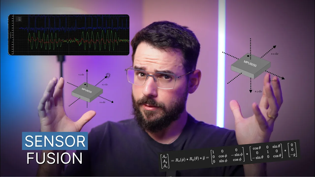
Implementation of sensor fusion algorithms, such as Complementary or Kalman filters, to combine accelerometer and gyroscope data and reduce noise and drift.
Utilizing the MPU-6050's onboard Digital Motion Processor (DMP) to offload complex mathematical orientation calculations (Quaternions and Euler angles) from the Arduino.
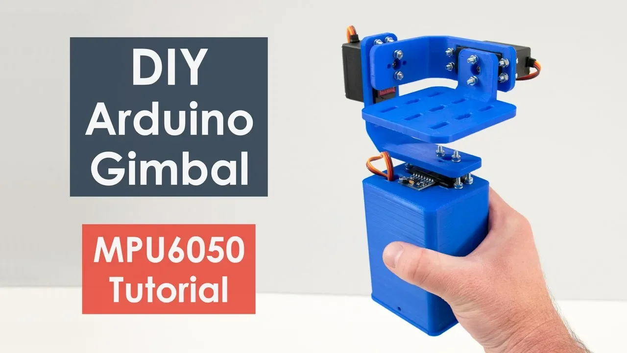
Developing a PID (Proportional-Integral-Derivative) control loop for real-world projects like self-balancing robots or camera gimbals.
Advanced calibration methods to calculate and programmatically subtract offset errors and temperature drift from the sensor readings.
456.3K views7.7Klikes29:18Original Release: 2016-07-18
what's going on guys Vlad with eeenthusiast decom here and in today's video we're going to be looking at the mpu6050 6 deges of Freedom breakout board which features a 3 axis accelerometer and a 3 axis gyroscope so I'm going to be walking you through the entire implementation of this particular integrated circuit I'm going to be showing you exactly which registers I'm pulling the data from exact exactly how to wire and write the software to be able to read the values what to do with the values what you can possibly modify in the program to kind of get something relevant more than just the pure raw data of the accelerometer and the gyroscope and as a very quick demonstration of the data that's currently being sent back to the Arduino serial Port you can look on your screen right now and as you can see you have the gyro readings in the grees as well as the accelerometer readings in um G's so let's take a look first of all at the gyroscope it is the speed at which you rotate above a uh certain axis so imagine my Z axis is going straight into the table so if you look at your screen right now the Z is about 0.4 de or so so that's the air that we're getting as soon as soon as I start rotating the board you see that number decrease because I'm going in a clockwise direction if I go counterclockwise that number is going to go up until I release the board as far as the accelerometer goes this is currently reading the gForce that is being exercised by Earth so once again this is in the Z axis you have 1G going down if I tilt the module along the Y AIS you can see this force is being spread uh evenly at 45° on the Y and the Z axis so that's just a very quick demo of reading some raw data and sending it back to the Arduino this is still quite a bit of an intricate method so I'm going to be discussing how I do it over I 2 C I'm going to be showing you the registers as I've mentioned before and walking you through the entire process so you can use this without any fear in all of your or any of your [Music] [Applause] project all right so let's cover the connections first so very simple circuit you have your power and your ground going to the breakout board as you can see it's labeled as VCC and ground followed by and SDA pin so these are going back to the Arduino Uno to pens A4 and A5 if you um refer to the picture that you have on your screen right now those are the pens which are uh and SDA respectively on the Arduino so we're going to be configuring those for the iqu C communication later on in this in the software uh followed by the ad0 pin so this is a pen once again I'm going to be posting a reference in the manual which specifies the reason as to why it is pulled down to ground this is actually internally pull down to ground but just to be safe you want to pull it down as well you can either pull it down or pull it up depending on which address you are going to be using in your software and once again I'm going to be making a reference to that once we get to that part but it is important to know what your ad0 PIN is uh in order to address this particular mpu all right so here's the software I have written for this particular tutorial it starts starts off by including wire. H Library this is the library which is used for the iare T communication notice that this is the only library that I am using there is a library available for the 60/50 mpu however it is very important to know how to access the registers on your own therefore I'm going to be explaining it uh from ground up without using that particular Library so the first thing I'm doing is creating three Longs for the acceleration x y and Zed those are going to be storing the values or the data read from the mpu itself creating three floats which are going to be used to calculate the G forces acting in the three directions Long gyroscope XY Z just as I mentioned this is going to be storing the raw data read from the gyro of the mpu float rotation XY y z we're going to get into that a little bit further but essentially it's going to be storing the rotational speed or velocity uh around those axes in my setup function very simple serial. begin 9600 I'm doing this purely for troubleshooting purposes and for demonstration purposes you might be uh doing something different with your data why. begin so this is the command that you will need uh to initialize your i squ c communication absolutely a must before you start reading and writing any data from from your iqu C uh enabled modules setup mpu uh let's jump right to that function before we discuss anything else all right so the main purpose of the setup mpu function is to one establish communication with the mpu and number two set up all the registers which we will be using in order to read the data back from the mpu into the uino so the first line is uh beginning by wire. begin transmission 0 b11 01 0000 so what is this uh what is this address mean so this is the i c address of the mpu and uh I'm going to be showing you in the uh data sheet where it is specified to be as such so if you go to the data sheet itself in section 9.2 you're going to have a section on iquit C interfaces so obviously iquit C is a two- wire interface com promise of signals serial data SDA and serial clock which we've connected on our board right here uh if you go down below you will see that the slave address of the mpu is b1101 00x which is seven bits long so what does the what does the X stand for so the least significant bit of the 7 bit address is determined by the logic level on pin a0 so if you remember dur in our connection you had a pin a0 which you connected to ground if you followed my instructions then your X will be equivalent to a z so this allows two mpu 60 x0 s's to be connected to the same I squ cbus so essentially what they're saying is if you wanted to chain a second mpu if you wanted to have a second reading you would set this particular address to a high and uh you would be really easily able to integrate that a is such so when used in this configuration the address of the one of the devices should be b11 010000 pin 80 is logic low just like we did here and the address of the other should be b1101 001 pin 80 is logic High all right so coming back to our program the next line is y. WR 0x 6B as I've notated here it is accessing the register 6B which are essentially deals with power management and c section 4.28 so let's take a look at the data sheet uh which re which essentially specifies the register map and as you can see I have it pulled up right here so the register map for this mpu is quite extensive uh on the left side leftmost side you will see the address of the register in HEX so that is exactly what we're looking for so if you scroll down you can uh you can look through these registers and I absolutely encourage you to do so kind of understand what they're doing but essentially we are going to be first of all interested in the register 6B so let's keep on scrolling down here's 6B as you can see there is a sleep mode there is a cycle mode there is a device reset bit the first question that comes to mind is how do you know that you need to uh work with this register in the first place and if you scroll down in the data sheet you will see a note which tells you that the device will come up in sleep mode upon power up so this is a very important uh note to kind of take care of because you do not want to stay in sleep mode if you're going to be constantly pulling the data from your device so this gives you an indication that you should be going to the register 6B so let me just quickly search for that and as you can see it brings us to the section 4.28 as I've mentioned before so here's the description of the register and you will have the full data sheet that you can go through and it will have a description for each and every single uh register on this mpu so This register allows the user to configure the power mode and clock Source it also provides a bit for resetting the entire device and a bit for disabling the temperature sensor so that's something to pay attention to if that's what you want to do uh by setting sleep to one the mpu 6xo can be put into low power sleep mode when cycle is set to one while sleep is disabled the mpu will be put into cycle mode in cycle mode the device Cycles between sleep mode and waking up to take a single sample of the data from the accelerometer at a rate determined so if you want to do something uh that is required to kind of only have a reading at a certain time or if you want to save battery power if you have such an application that is absolutely something that you need to look into so upon power up the mpu clock source defaults to the internal oscillator however it is highly recommended that the device be configured to use one of the uh gyroscope gyroscopes or an external clock source so if you want to use a different clock Source it is highly recommended by the data sheet but we're not going to be uh dealing with that right now so our goal is to pretty much set all of these bits to zero to make sure that we are no longer in sleep mode so let's take a look at the right that we are doing so the right and I've simplified you can do this in HEX or you can do this in binary so when you want to do it in binary you put a z b in front and then you write to the bits that you like you write the bits that you want to write to this particular register so imagine first of all you have to select which register you want to write to and then you write the value that you would like to write into that register so in this case I'm writing all zeros to make sure that we're on the we're not in the sleep mode we're not in um any of the external clock modes and uh followed by that I'm ending transmission so once again I highly encourage you to go through the shift register and make sure you fully understand what is going on there all right so the next step in our function is to be setting up the accelerometer and the gyroscope parameters and where these values are coming from are from the data sheet so let's go back to the data sheet and take a look at the features of the gyroscope as well as the accelerometer so in the first line of the specifications you can see that there's a digital output XY Z axis angular rate sensors with a user programmable full scale range of plus - 250 plus - 500 up to plus - 2,000 de per second for the accelerometer you have a similar line which says that there is a digital output uh based on a programmable full scale range of plus - 2 uh G's up to plus - 16 G's so what does this really really mean is that you will need to select a range so let's start with the gyroscope you have plusus 250 up to plus - 2,000 so let's very quickly this discuss these numbers so first of all it is in degrees per second and what this means is that your module will be able to detect how many degrees per second of a rotation are you doing around this uh particular axis so you can read it about the three axis if it's doing a weird rotation but if it's only about one axis you can detect that particular speed and what this um boils down to is or what is the best setting for you is essentially what is going to be the limit for your project and let me quickly break this down to you into something you can understand a little bit more so 250° per second equates to uh 250 / 36 60 * 60 and this number is going to be an RPM so imagine you are doing 250 out of 360° in a second and you're multiplying that by 60 seconds to give you a value in uh revolutions per minute so 41.6 RPM so what this really tells you or what the data sheet is telling you if you select this particular setting so plus or minus 250 you will only be able to detect up to 41.6 RPM uh revolutions and this is something to pay attention to because depending on which setting you are going to use number one you will either gain the the RPM so at 2,000 obviously you're going to have a higher RPM let's quickly do that math 2,000 ided 360 * 60 so 2,000 / 360 * 60 uh 333 do3 RPM at this particular setting so first and foremost you are going to be limited on your RPM but also as you go higher up there is no there is a tradeoff because if you refer back to a to the specification of the gyroscope you will see that your sensitivity will be decreasing as you increase the full scale range so you need to be uh essentially your goal is to select the most optimal range for your particular project and the way to go about this if you know you have something that will be rotating at around let's say 25 RPM you want to go absolutely with the highest uh sensitivity you can get so you would select plusus 250 if you have something that's rotating 300 RPM then you must or if you want to detect of that range you must select this particular setting so that's something that you want to pay attention to as you play with the registers I'm going to be mentioning in it in just a moment the other thing that you also want to consider is are you going to have spontaneous movements are you going to have a continuous reading of RPMs or do you even care for example if you have spikes over 100 RPM and you can you know you only want to detect if it is moving or not moving uh so all of that needs to go into consideration for your project all right so let's get back into the software and take a look at the next section which is going to be the implementation of the accelerometer register so as you can see it begins the same way wi that begin transmission 0 b1101 which is the address of the mpu as I've mentioned a couple of times I am going to be writing to the register 0x1c so 1C register I'm going to be taking a look in that on that register in just a moment and I'm going to be writing all zeros to this value in order to set the accelerometer to plus and minus 2 GS so let's take a look at the uh this particular register as you can see it is the accelerometer configuration register the description is this register is used to trigger accelerometer self test and configure the accelerometer full scale range the register also configures the digital high pass filter we're not going to be going into the self test uh settings in depth but I encourage you to read up on them as you uh go along but essentially you have eight bits in this register just like you do for the gyroscope you have X aore SD self test yaor self test z a self test and then you have the AFS select bits which uh which are the ones that we are interested in if you scroll down this you will see the AFS select selects the full scale range of the accelerometer outputs according to the following table so so depending on what you set those bits to 0 1 2 and 3 you can select a different full scale range plus or minus 2gs plus or - 4 plus or - 8 or plus or minus 16 and how you do that you will I'm going to give you a quick demonstration so for example let's say you wanted to select plus or minus 16 in binary your three is going to be a 1 one so let's scroll back up you will need to set the bit and uh three and four to one one so if we go back to the program if you wanted to set this to plus or minus 16 let's take a look this is bit 0 1 2 3 so three and four will be set to a 1 one so if you were to write this to your register right now you would be setting the accelerometer full scale range to plus or minus 16 G's uh just for the purposes of this demonstration we're going to be going with plus or minus two but I wanted you to know how to do that should you desire to use that particular setting for your project let's very quickly discuss what the accelerometer is actually reading on the mpu itself so what it is detecting essentially is the forces acting on it in the three axes that we've discussed so XY Z and right now because it is lying on a flat surface the only force that is act acting on it is the force of gravity going downwards into the Z axis of 1 G for example if right now I start moving this in the X Direction I am exerting a force right so I'm exerting a force on this particular module and it will detect a certain certain force on the x axis if I was to push it on the side it would detect something on the Y AIS one important thing to note that if you were to tilt some tilt the module for example you can you're going to start acting the you're going to start exerting this uh gravitational pull on the x axis or Y axis depending on which way you tilt the module or both ways if you desire to do so but essentially you can calculate the angle from the perp from the perpendicular to whatever angle from the gForce so that's that's a very important thing to know I'm not going to go too much into trigonometry but with uh few signs and cosines you'd be able to figure out that particular angle should you desire to do so so that's pretty much much all for the settings of the accelerometer and that would terminate our setup mpu function so again if you have any questions any doubts feel free to post them in the comments down below all right so scrolling back through our software to where we left off so set up the mpu should be fairly clear for you right now we have the loop function which is going to be recording the accelerometer registers the dryer scope registers printing the data to the serial port and then creating a delay of 100 milliseconds so let's scroll down to the record accelerometer registers function and take a look at that the beginning of this function should be very familiar to you wire that begin transmission this is again the address of the mpu wire that right 0x 3B so the starting register for accelerometer readings so what does this refer to let's go back to our register map and look up 3B I've referenced this before but once again and you should be going through this on your own and kind of looking at what you want to see but accelerometer measurements so description these registers store the most recent accelerometer measurements accelerometer measurements are written to these registers at the sample rate as defined and registered 25 so if you want to change anything there you want to make it quicker slower uh feel free to do so we're not going to be playing with register 25 in this particular tutorial the data within the accelerometer cens sensors internal register set is always updated at the sample rate so feel free like I said to play with that as you need each 16bit accelerometer measurement has a full scale defined in Excel FS register 28 for each full scale setting the accelerometer sensitivity per LSB in Excel X Out is shown in the table below so I wanted to address what this really means so as the uh example for this tutorial I went with the plus or minus 2 G's range specified below and as you can see the LSB sensitivity is 16,384 per G so 16384 LSB per G so what this essentially means is that the the value that you will get back from this register will need to be calculated to actually display you a number in G's so you will get so for example let's um let's say you read something like 20,000 from your uh shift register which we've discussed here you will you want to optain the value in G's so uh question mark G's for example so this question mark is going to be calculated as such you need to divide 20,000 by your 16384 and this will give you a value in G's 20,000 / 16 384 and this would would be equivalent to 1.22 G's of force acting on that particular axis so this is a very important concept because a lot of people uh I've seen online are confused by what they are they are getting exactly out of the accelerometer and gyroscope readings but essentially you're getting a value which you will need to translate to something meaningful to you but this data she is specifying what this translation needs to be essentially so depending on which full scale range you have selected you will need to do a different division and calculation in order to get the correct value in G's so let's take a look back at the program so we're writing to this register 3B and transmission so we're essentially starting a register request so we're writing something to the register and we're ending the transmission and we're requesting from the register again here it's the address of the mpu and we're requesting six of those registers 3B through 40 so if you refer back to the data sheet 3B through 40 the there are six of them and it's x x y y z z so we will need to recombine uh the X Y and Z respectively but essentially while write. available is smaller than six we store the values in the X Y and Zed values so the first two bytes are stored in X middle two bytes are stored in y and the last ones are stored in Z so very simple read function on our IC and as I mentioned before I am going to be processing the accelerometer data in order to get something meaningful so process accelerometer data and here you have the function which is doing exactly what I've explained on the paper right here so it is dividing the reading that you get from the register by 16,384 do0 to make sure that it is a long and not truncated to an in processing all the EX ometer data and getting that to a meaningful value for us the next step is going to be reading the gyroscope registers and this is uh I'm not going to be going in depth in this implementation but it is exactly exactly the same thing as I've explained for the accelerometers so wire that right 0x 43 and there's going to be six bytes for this particular reading as well so it's going to be x y and Zed for the gyroscope and then I'm going to be processing the gyroscope data very similar to what it was with the accelerometer except that now we are dividing by 131 and you can refer to the either the data sheet or you can refer to the sensitivity so as you can see it is LSB per degrees per second that you need to divide to in order to get the rotation in degrees so that's something that you want to pay attention to you want to get something that is Meaningful and once again if you have any questions Post in the comments down below and lastly if you remember we're calling a print data function which is going to be displaying all of our data XY Z axes for the gyroscope as well as the accelerometer should be fairly explanatory at this point I'm not going to be going through this too much but let's take a look at what we are seeing on the serial monitor so once again as I've explained we are currently getting all of the data from the mpu and we are Translating that into degrees for the gyroscope and G's for the accelerometer so let's first start again with the gyroscope and let's create a rotation around this particular axis so as you can see it is the Y AIS and it is changing from just a simple zero or very close to zero it's kind of oscillating back and forth a little bit but as I rotate up and down it goes all the way to to uh 250 and then go goes back down and as you can see there's no there's absolutely no way for me to kind of make this go above 250 which was the setting that we had used for this particular register similarly on the x axis you can detect this rotation rotational movement and the same for the Z axis and obviously you can do a combination of all three and you you will be detecting something uh that you can process if you desire desire to do so if you want to balance for example a quadcopter if you want to do something um uh like a plane balancing for example scheme that is very feasible for the accelerometer as I mentioned it measures the force that is acting on the mpu so for example if I start bringing this up you will see that the Zed will go up and if I drop it then it should go slightly below zero I don't know how noticeable it is uh for example the Z if I start moving or jerking the the module back and forth then you you should be able to see that Force similarly as I've mentioned before if you tilt the module uh you can see that the gForce is acting right now on the X and the Z axis so what this allows you to do is to calculate the angle at which your module is being positioned and use that data as I mentioned to control a quadcopter to control an airplane and uh other applications like a robot arm for example if you want to go that route but you can very easily see that if both values are matched right the force is equally distributed before between the two of your axes that means you are at 45° if uh it's zero then obviously it's only in the Z axis if we put it on its side let's take a look so right now all of the all the force is on the y axis along with this module and uh I I believe I mentioned this but there are markings on which axes are going in which direction on the module itself so it makes it very easy very convenient for you to see and um yeah that would be all for the demo uh I would like to come up with some projects for you I'm planning to do a uh stop kind of detection system with this particular mpu but let me know uh what would what would you like to see where you're going to apply this for uh what kind of other questions and or projects you would like me to address with regards with this uh to this particular module thank you guys for watching hopefully this was an insightful video and I see you guys next time bye and what do I need to learn or which platforms do I need to learn in order kind of get to that level and the reason why I wanted to answer that question is because I know that a lot of my view
Up Next
19:20
Self-Balancing Robot Mechanics: Inverted Pendulum Control Theory
@NoahZipin
11.3K views•2020-06-02

30:32
Ultrasonic Transducers: Resonant Frequency Measurement and Horn Design
@imajeenyus42
229.9K views•2017-02-22

54:16
Polymer Environmental Degradation: Mechanisms & Stabilization
@iit
1.8K views•2012-07-10

33:39
How a Student's Question Saved a NYC Skyscraper from Collapse
@veritasium
22.8M views•2025-04-26
Related Study Plans & Knowledge Roadmaps
Structured learning paths in Engineering
engineering
Building Acoustic Levitators: Physics & Arduino
01The Physics of Sound and Standing Waves
02Piezoelectric Transducers and H-Bridge Drivers
03Arduino Programming: Generating 40 kHz Signals
+ 2 more learning modules
14h5 modules
Explore Roadmap
engineering
Building Peltier Cloud Chambers: Particle Tracks
01Cosmic Rays & Cloud Chamber Physics
02Thermoelectric Cooling (TEC) Fundamentals
03Custom Liquid-Cooling Loop Design
+ 2 more learning modules
18h5 modules
Explore Roadmap
engineering
Yagi-Uda Antennas: Modeling, Build & VNA Test
01Introduction to RF and Antenna Fundamentals
02Yagi-Uda Antenna Design Principles
03Antenna Modeling and Simulation in 4NEC2
+ 2 more learning modules
18h5 modules
Explore Roadmap
engineering
ECG Monitor Design: Op-Amps, Filters & Noise
01Electronics & Breadboard Basics
02Op-Amps and Instrumentation Amplifiers
03Bioelectricity and ECG Fundamentals
+ 2 more learning modules
18h5 modules
Explore Roadmap