


![1) Adi Diferansiyel Denklemler : Dif. Denklem Tanımı ve Örnekleri [Ordinary Differntial Equations]](https://i.ytimg.com/vi_webp/BkVCADUC2wQ/maxresdefault.webp)

















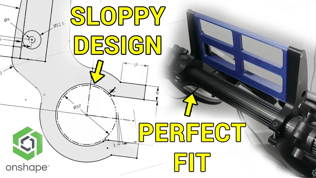


A self-balancing robot operates on inverted pendulum principles, where the robot maintains balance by accelerating its wheels in the same direction as its tilt angle to keep the center of mass above the pivot point, rather than using direct torque control; this is achieved through a PID control loop that maps motor velocity to the robot's angle, with the mechanical design utilizing aluminum extrusion chassis, polycarbonate panels, and dual motors with quadrature encoders for precise velocity control.
Self-Balancing Robot Mechanics: Inverted Pendulum Control Theory
Added:Classical Mechanics and Rotational Dynamics: Understanding torque, moment of inertia, center of mass, and Newton's laws of motion for rigid bodies.
Ordinary Differential Equations (ODEs): The ability to model physical systems mathematically to describe how state variables change over time.
Basic Feedback Control Theory: Familiarity with open-loop versus closed-loop systems, transfer functions, and the fundamentals of PID (Proportional-Integral-Derivative) controllers.
State-Space Representation: Understanding how to represent a dynamic system as a set of input, output, and state variables in a vector-matrix form.
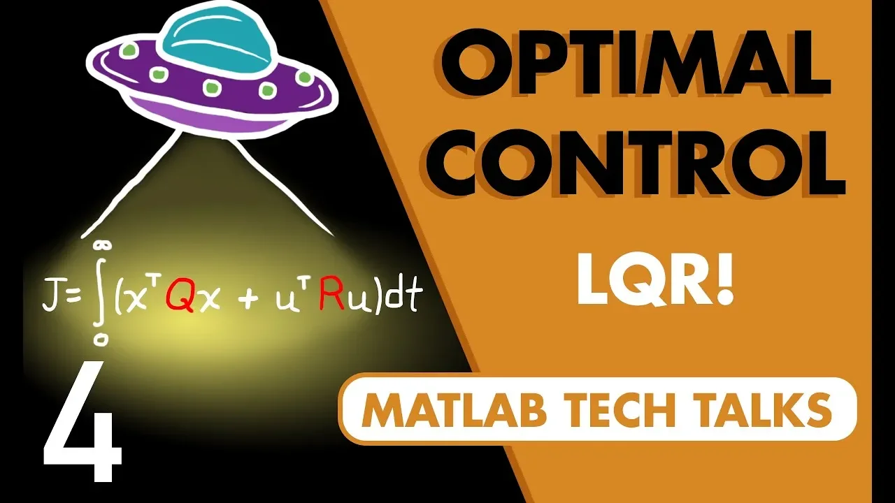
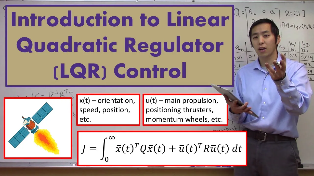
Linear Quadratic Regulator (LQR) Optimal Control: Transitioning from classical PID control to modern state-space control methods to stabilize multi-variable systems efficiently.
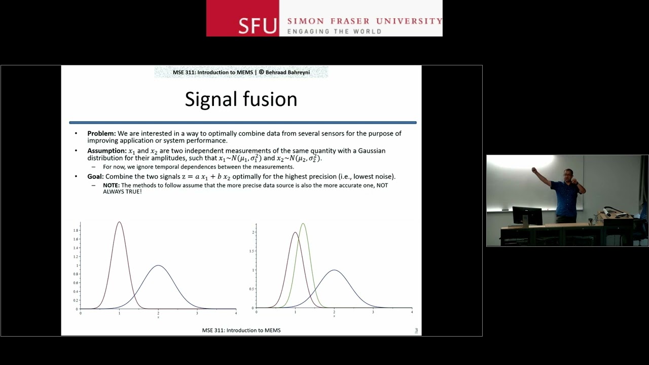
Sensor Fusion and Kalman Filtering: Learning how to merge noisy accelerometer and gyroscope data to estimate the actual tilt angle and angular velocity of the robot.
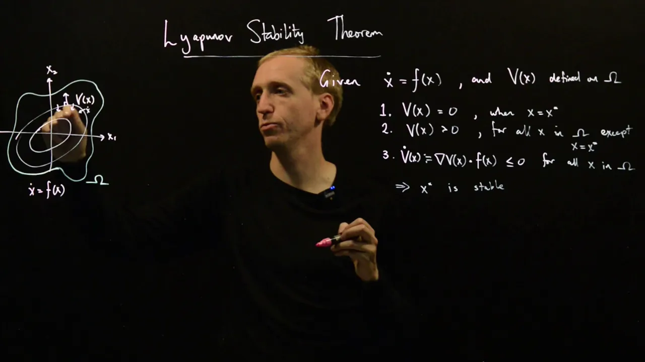
Nonlinear Control and Lyapunov Stability: Exploring advanced control strategies for stabilization when the system undergoes large deviations where linear assumptions fail.
Practical Hardware Integration: Implementing the control algorithms on embedded microcontrollers (such as Arduino or STM32) using real motors, encoders, and Inertial Measurement Units (IMUs).
11.3K views331likes19:20Original Release: 2020-06-02
Hey what is up my name's Noah and welcome to the channel so right now which at the time of the recording is the year 2020 most things are on lockdown and I'm kind of here with not much to do so instead of just wasting my time I'm going to be doing a series of independent projects and uploading them here on the channel so I can share them with you to start off we're gonna be building a self-balancing robot I'm guessing this will be about a four-part video series where we go over everything I've done including my failures and show you how to build it yourself let's get started before we get to the design I want to explain a little bit about what a self-balancing robot is and our strategy on how we're going to approach this a self-balancing robot is pretty much self-explanatory it's a robot that keeps itself upright and self balancing robots are seen in everyday life all the time think about the Segway or the new hoverboard or even a self-balancing unicycle and all of these devices have one thing in common they're all inverted pendulum so I want you to think about a time when you've ever tried to balance something on the end of your finger in fact I have something like that right here so an inverted pendulum is just like a normal pendulum except this time its center of mass is above the point of rotation so something like this is inherently unstable because it's always trying to swing down here but right at the very top it actually is stable because gravity is acting along the axis of the ruler so in a dynamic system like this it's a it's called a fixed point or a stationary point and so in other words there's no torque or moment about the axis of rotation at the very top but when the ruler tilts just a little bit there is that torque and it's gonna swing down so how do we stabilize something like this well one way you can stabilize the ruler is actually to use something like a motor or a servo which would essentially sit right here at the pivot point and whenever the ruler kilts a little bit it would exert an equal and opposite torque in the in the opposite direction and just kind of hold it up and stabilize it that way but that's a little boring so we're not going to approach it like that another way you can stabilize an inverted pendulum is actually to oscillate the pivot point vertically this is a seriously cool effect called capitis pendulum and the link to the source of this video I'm showing is in the description this effect is really complex mathematically so we're not going to approach it like that what we're actually going to do is stabilize our self balancing robot the same way we do with our finger and the ruler when the ruler tilts in one direction what we do is we accelerate our finger so that our finger sits right underneath the center of mass of the ruler so that way there's no net torque and effectively the ruler stays upright but how does accelerating our finger stop the ruler from rotating well what happens is actually by accelerating the pivot point we're changing the angular velocity of the center of mass of the pendulum which means that we're inducing an angular acceleration on the inverted pendulum and by that we create a torque that acts here parallel to the pivot axis that counteracts the torque created by gravity on the pendulum so that's how it kind of stays upright the trick is to accelerate my finger just enough so it completely cancels out the torque created by gravity so how do we do that well I'm not quite sure yet but here's my thinking so the state of this dynamic system right is based on the position of my finger as well as the angle with respect to the vertical that the pendulum makes so this is a two degree of freedom system right so basically to control this I would need to know both the angle and the position of my finger or the the wheels in the case of a robot if I really want it to be technical what I could do is find the equations of motions of this dynamic system either by using the lagrangians we're actually Newton's second law and that would get me a system of nonlinear differential equations and at each fixed point right a fixed point would be at the very top or at the very bottom right where it's gonna stay stabilized I could linearize the system at that fixed at each of those fixed points using the Jacobian matrix and then I could create a control algorithm based on that system of linearized equations there is a link in the description by Steve run from the University of Washington where he does this and create something called a linear quadratic regulator and it's really cool I can just barely understand it so instead of doing that I think what I can do is actually just map the speed of the motor to the angle of the of the robot because I want to move the robot in the same direction as the angle right so that way I move the center of mass above the pivot point so we'll get into the technical details later but I think what I'm going to end up doing is using something called the proportional integral derivative loop and basically control the velocity of the motor with the sensor value being the angle of the robot for now let's check out what we're going to be building and get into the design [Music] so here is the final design the chassis is made out of 2020 aluminum extrusion because I really wanted it to be a durable rigid frame and aluminum extrusion which is commonly used in like DIY 3d printers is really modular tool and it's lightweight and durable the frame is held together using these 3d printed brackets for the 2020 extrusion that I made in fusion 360 and I think they turned out pretty nicely I'm going to be using 220 D Pololu metal gear motors along with two hall-effect quadrature encoders which is going to allow me to control the velocity of the wheel I've created these motor brackets here and that's what the entirety of the robot is going to be mounted on I don't think I should have any like parallel bars shift because I have two corner brackets and opposite sides here and here so I think I should be okay with that the back of the frame is made out of 16 inch thick polycarbonate sheet that's about one point six millimeters and I just thought that it would be a nice touch I could paint it red and it would look really nice along with the wheels I'm going to use I have these wires here this I'm just gonna bend some coat hanger and stick it in two holes I have created in V in the motor bracket and I feel like that's necessary because as the robot rotates I don't want it to damage any of the internal electronics so I'm gonna have these here they're at a 35 degree angle so that way it can just catch itself as you can see the wheels here are really thick and I thought that would be necessary just because it might be easier to stabilize that's just a theory and also I'll be able to go over rougher terrain like sidewalk and even grass later down the line as for the electronics I'm going to be using I'm going to base everything on an Arduino Uno so you can see here I had the programming of court place so I can program it really easily it's gonna be powered using this 9-volt battery but the brains of this operation is really going to be this module here and this is the MPU 6050 inertial measurement unit I'll go over this more in the electronics video but this essentially is going to allow me to read the angles of the robot so I'll be using this reading the angles along with the quadrature encoders to set the velocity of the wheel I have an LM 2 9 8 n motor driver which operates on a dual age bridge which I will go over in the electronics video along with a potentiometer to set the set point of the inertial measurement in real time so I think this is a pretty solid design our first step is to get printing these motor brackets along with the chassis brackets let's check it out [Music] [Music] [Music] [Music] [Music] all right so this is looking really good and now it's time to cut the polycarbonate sheet which is the backing and the front panel of the frame so what I'm going to do for that is actually export the sketches I created in fusion 360 and I can take these sketches and export them as a DXF file open them in Adobe Illustrator and print them on a piece of paper and cut them out that way [Music] all right we have these place down let's put them out on a piece of paper and cut out the plastic [Music] [Applause] [Music] alright and with that we have completed the mechanical assembly of our self balancing robot for what it's worth I think this turned out really well and I know what you're thinking the top and the back aren't read I just don't have any red spray paint with me our next steps are to get the electronics in here and program at using the Arduino IDE those are gonna come out in future videos and I'll get those out when I can thank you so much for watching and if you want to see more content like this hit the subscribe button I'm Noah thanks for watching and I'll see you around bye [Applause] you [Applause]
Up Next

29:50
Arduino PID Controller Implementation Explained Step by Step
@careyian
104.5K views•2023-02-26

30:32
Ultrasonic Transducers: Resonant Frequency Measurement and Horn Design
@imajeenyus42
229.9K views•2017-02-22

54:16
Polymer Environmental Degradation: Mechanisms & Stabilization
@iit
1.8K views•2012-07-10

33:39
How a Student's Question Saved a NYC Skyscraper from Collapse
@veritasium
22.8M views•2025-04-26
Related Study Plans & Knowledge Roadmaps
Structured learning paths in Engineering
engineering
Building Acoustic Levitators: Physics & Arduino
01The Physics of Sound and Standing Waves
02Piezoelectric Transducers and H-Bridge Drivers
03Arduino Programming: Generating 40 kHz Signals
+ 2 more learning modules
14h5 modules
Explore Roadmap
engineering
Building Peltier Cloud Chambers: Particle Tracks
01Cosmic Rays & Cloud Chamber Physics
02Thermoelectric Cooling (TEC) Fundamentals
03Custom Liquid-Cooling Loop Design
+ 2 more learning modules
18h5 modules
Explore Roadmap
engineering
Yagi-Uda Antennas: Modeling, Build & VNA Test
01Introduction to RF and Antenna Fundamentals
02Yagi-Uda Antenna Design Principles
03Antenna Modeling and Simulation in 4NEC2
+ 2 more learning modules
18h5 modules
Explore Roadmap
engineering
ECG Monitor Design: Op-Amps, Filters & Noise
01Electronics & Breadboard Basics
02Op-Amps and Instrumentation Amplifiers
03Bioelectricity and ECG Fundamentals
+ 2 more learning modules
18h5 modules
Explore Roadmap