![💪MECÁNICA de FLUIDOS. APLICACIÓN de BERNOULLI en PÉRDIDAS y POTENCIA de una BOMBA [👉ENTRA Y APRENDE]](https://i.ytimg.com/vi/yXkKwv36RsM/maxresdefault.jpg)







![[토목시공기술사] 상하수도 총정리](https://i.ytimg.com/vi/f_BYHpaGBLM/maxresdefault.jpg)




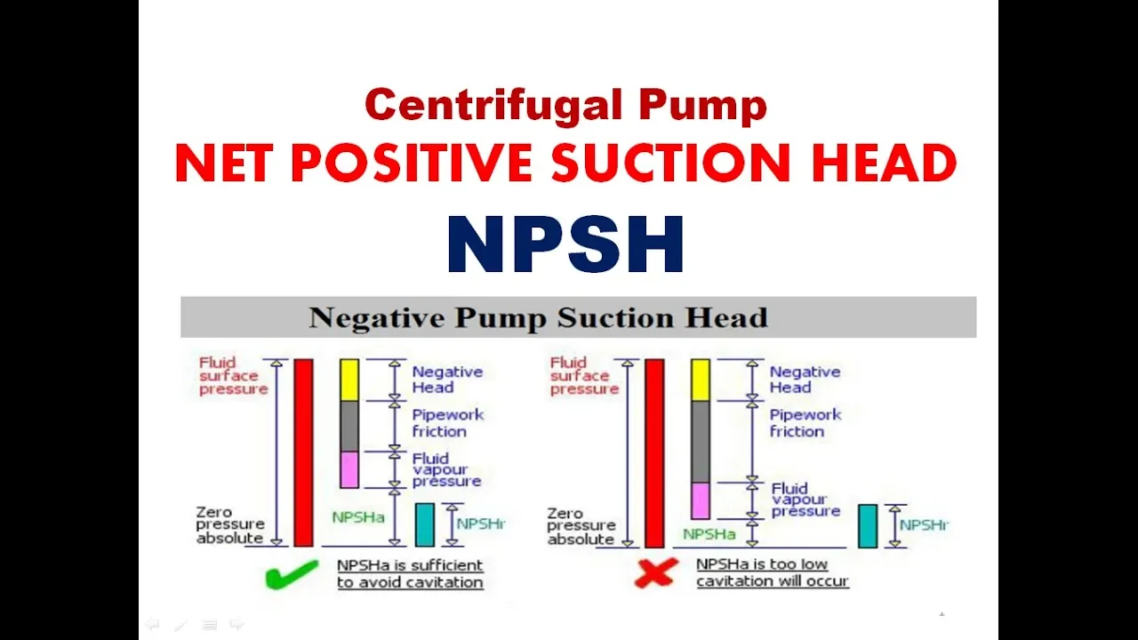


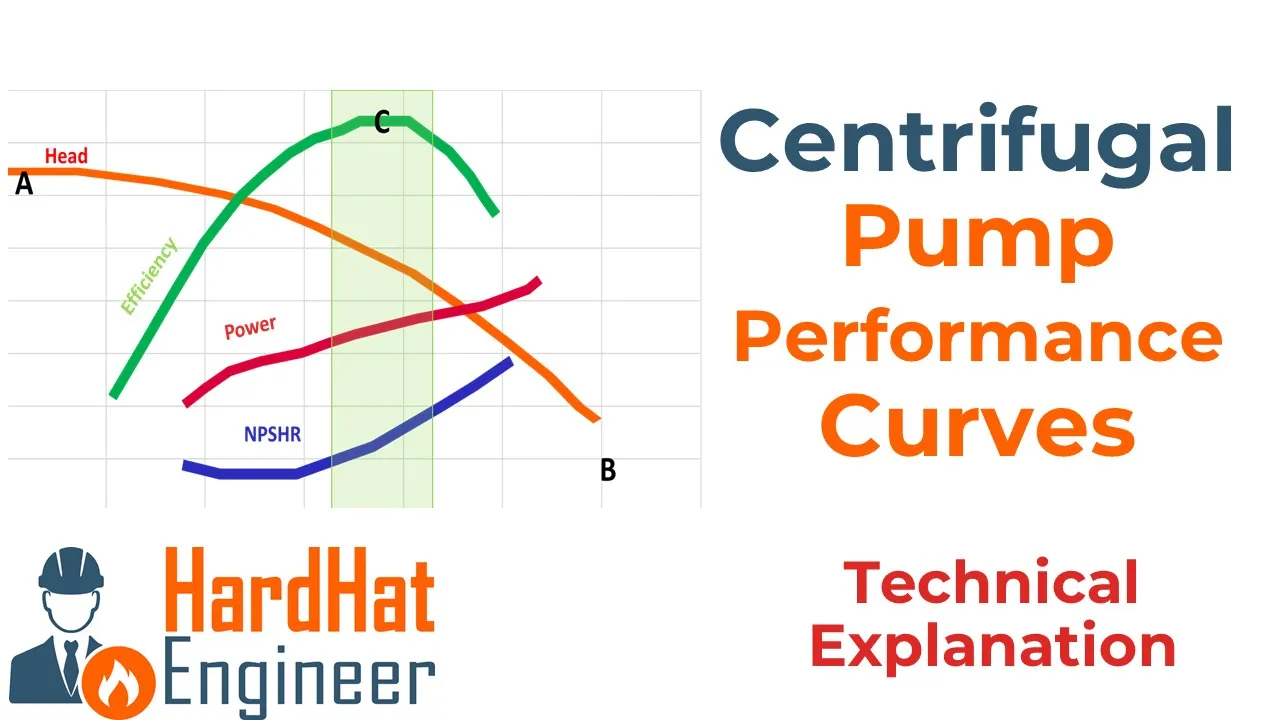












Intake structures are essential components of water supply and wastewater systems that withdraw water from surface sources like rivers, lakes, reservoirs, and canals, featuring designs such as wet intakes, dry intakes, and specialized configurations for different water bodies; pumping installations require careful consideration of pump selection based on specific speed (Ns = 3.65 × n × √Q / H^(3/4)), sump design to prevent vortex formation and ensure uniform flow distribution, and critical parameters like Net Positive Suction Head (NPSH) to avoid cavitation, with centrifugal and reciprocating pumps being the most commonly used types in water supply schemes.
Water Intake Structures & Pumping Installations | Engineering Lecture
Added:Fundamental principles of fluid mechanics, including hydrostatic pressure, Bernoulli's equation, and head loss calculations.
Basic hydraulics of open channel and pipe flow, specifically flow rate, velocity, and hydraulic gradients.
Introductory concepts of water supply and wastewater systems, including the general layout of treatment facilities.
Elementary pump theory, including centrifugal pump operation, system head curves, and Net Positive Suction Head (NPSH).
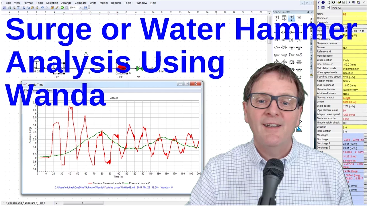
Advanced hydraulic transient analysis (water hammer) in pumping mains and the design of surge control devices.
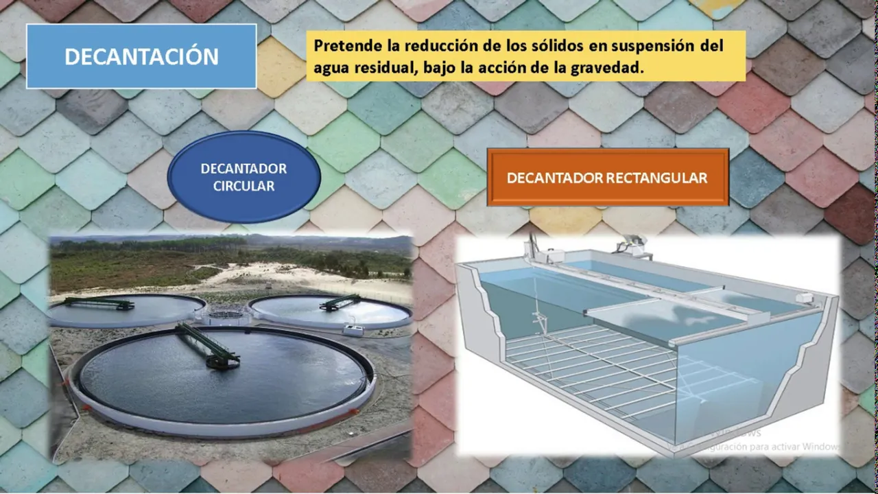
Integration of intake and pumping systems with primary water treatment processes like screening, grit removal, and sedimentation.
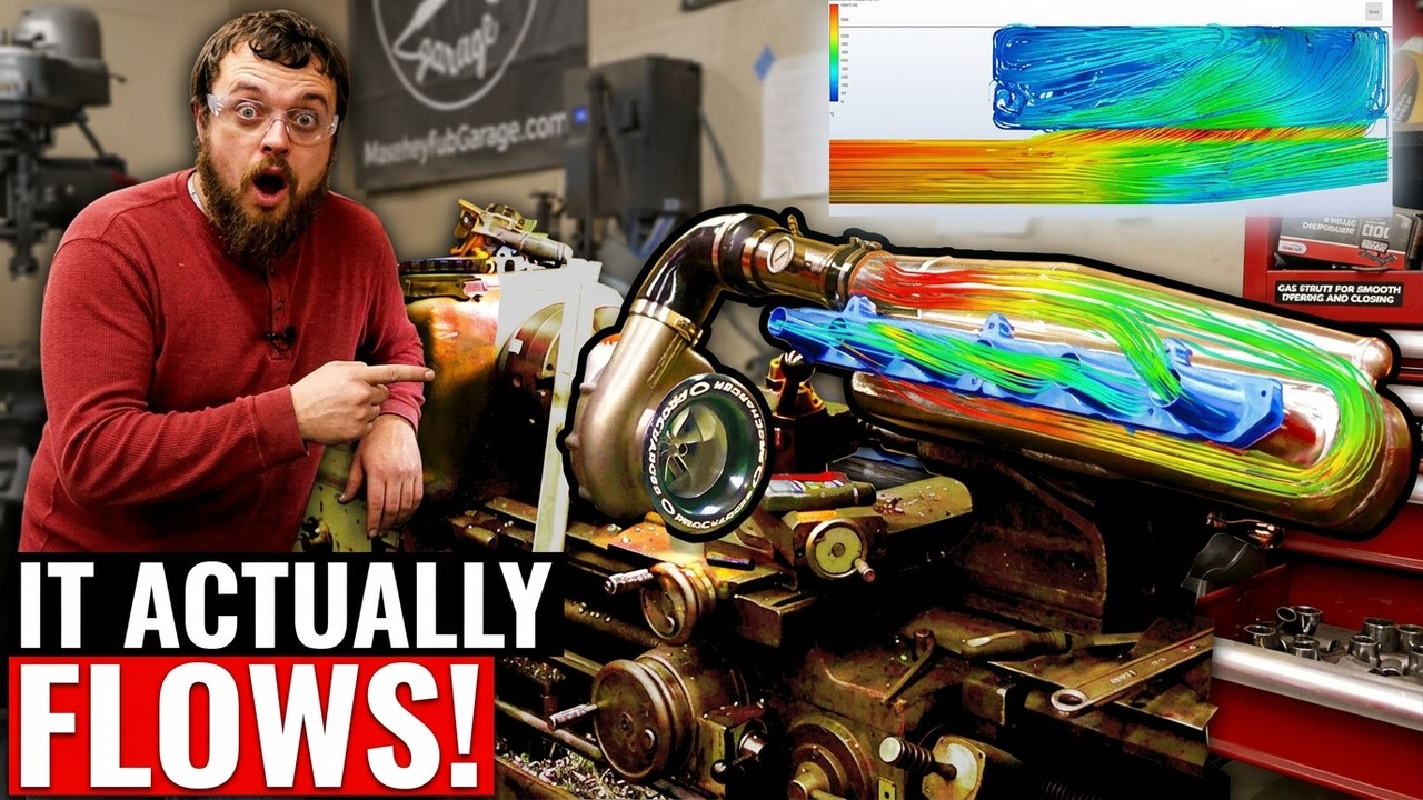
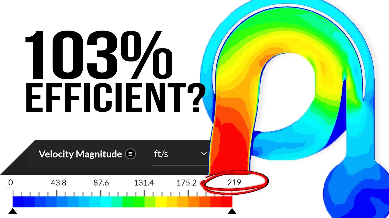
Application of Computational Fluid Dynamics (CFD) software to model and optimize flow patterns at intake structures.
Energy efficiency auditing and lifecycle cost analysis for large-scale municipal pumping installations.
59.8K views348likes59:35Original Release: 2007-12-27
[Music] [Music] oh sh sh sh [Music] see in this lecture we will discuss about intake structures and pumping installations which are an integral part of any water distribution Network or they could be a part of seever systems also the pumping is required in water supply systems to transport water from source to the treatment plant Source could be at a lower elevation and treatment plan could be at a higher elevation so we need to lift the water from a lower elevation to a higher elevation we need pumping for that we also need pumping because we have to get over the frictional losses that could be coming in the pipeline then we also require pumping many times in water distribution networks because the pressures could be very low and we have to meet that minimum 7 m of head of residual pressure and and we need to boost up these pressures so the pumping is also required to boost up pressures in water distribution networks in certain cases we also need pumping in water distribution networks to transport water through treatment plants because a lot of energy loss occurs in the treatment plant uh piping so we have to get over this frictional losses and we need to have pumping for transporting water through treatment plants pumping is required in waste water schemes also to lift septic tank affluent from a lower elevation to a higher elevation many times we have to lift sanitary and Storm seage from underground drains to treatment plants which are above the ground in uh SE systems we also need to lift water from a lower elevation to higher elevation if the drain slope is much higher than the slope of the prevailing ground in such a case case over a distance the drain will be buried deep inside the ground and that will be very uneconomical from the point of view of constructing and installation also it is uh difficult to maintain such pipes so we have to bring the drains to a higher elevation in such cases we need to lift water from a lower elevation to higher elevation in waste water schemes so there also we have the requirement of pumping before we go and look at the pumping we look at the intake structures which are the first part of any water uh Supply scheme a uh intake is a device or structure to be placed in a surface water source to permit the withdrawal of water now the intakes could be wet intakes or dry intakes depending upon whether the water is temporarily stored in that intake structure or not again intakes could be River intakes Lake intakes or Reservoir intakes or Canal intakes depending upon the source from which we are taking the water for example in this figure you see this is an River this is a river intake here we have the bank and this is the river here it's almost inside the river this intake and this is the high flood level my pump should be or the pump house should be above the high flood level to protect it from the flood damage and I also have this low water level my intake structure should be able to draw water even when the water is at a low water level so we have two different there U pipes here which can draw water from the river to the intake structure that is a high level pen stock and a lowle pen stock and there is a screen here at the front of the pen stock this screen is uh preventing the debris from entering into the intake structure or entering into the treatment works there's a pump here that the suction pipe of the pump is like this and this is the screen here which is again having the function of screening the fine material from entering into the suction pipe and consequently into the pump and then damage the pump now this level here the screen level are the bottom level of the suction pipe should be low low water level and there should be some sufficient head available here otherwise there could be um an air entrainment now this is called an intake well and the water level in the intake well will be slightly lower than whatever is the prevailing water level in the river like for example if this is a high flood level and the water is uh water level is at this location in the river then the water level in the intake well will be slightly below that that difference in the head accounts for the head loss in this piping system now we also have a valve here which which can be used to control the entry of water from the river into the intake well and this is the pump house and the delivery from the pump is taken into the treatment box so this is a wet intake well system for a river intake we see the next type of river intake this is called a jackwell and here we keep the pump house not inside the river but away from the river on the banks not too far away but slightly away from the banks in this case here you have this intake structure now this intake structure is placed much below the row water level so that water can enter into the well even during the low flow season here this is the pipe this is the intake pipe and there is a uh screen here which screens the debris from entering into the intake well or Jack well and we have a pump here which has a foot wall basically this foot wall is required for priming of the pump and this foot wall or the low end of this suction pipe should be below the River water level and there's a valve here which can be operated so that I can control the amount of water that is coming into the intake well and the pump house is much above the high flood level so that the flood damage to the intake structure is minimized and the delivery from the pump is taken to the treatment works so this is another type of an intake structure or river intake structure now we look at the intake structure for a uh when uh the kind of intake structure we adopt when we want to take water from a reservoir here we have the reservoir and this is the earn Dam or embankment that is U basically containing the water in the reservoir and we want to take this water to the treatment works and here we put this intake structure this is the intake structure and the water can enter into this intake structure through these These are the inlet ports which are placed at three different levels these Inlet ports so water can enter into the in structure from any of these Inlet PS and then the control of flow into the intake structure is done by these Gates and so this is what we call the gate house and we need a foot Bridge from the embankment to the gate house and what water which is uh which enters into the intake structure is carried to through this particular pipeline to the treatment works either I can have a pump here if I need to lift the water or it can go by uh go Flow by gravity to the treatment works so this is an intake with entry ports at different levels another type of intake here there's there's only one entry Port there not too many entry ports the uh water enters the intake structure and then it goes through the conduit to the treatment works and I can have a pump house here uh if it is required but the main point is water enters into this conduit or into this intake structure through only one port and we have a trash rack structure here which will prevent the entry of debris into this conduit or into this intake structure here and this entry Port is kept at the bottom of the reservoir and so the water can enter into this conduit even when the water level in the reservoir is very low we have another type of intake structure this is what we call a dry well intake structure or dry intake the it's dry intake because the water is never stored in this intake structure itself I have this outlet pipe here which is coming and then entry into this out outlet pipe is through this vertical Riser and there are multiple entries into this vertical Riser which are which take water from the reservoir and then there's a strainer and um all the fine material and the debris is U not uh allowed to enter into this pipe and but the ports are at different levels water enters into this pipe the Riser and then directly flows through this outlet pipe so that way there is no water which is stored in this intake structure at all so this is completely a dry well okay or a dry intake structure and we have a valve Rod here to control the flow into the outlet pipe so this is a dry dry intake for a Reser to take water from a reservoir then we also may have a reservoir where the water is stored uh behind a gravity Dam so if I have a gravity Dam like this then I can have one pipe the intake pipe which is going through the body body of the gravity Dam and there's a bell mouth here so that there's a smooth entry into this uh intake pipe and at the Bell mouth at the entrance to the Bell mouth we have this trash rack structure which prevents the entry of debris and then uh suspended matter into this uh uh Inlet uh or intake pipe and the flow into the intake pipe itself can be controlled by a gate and this is the ho cable for the gate which is and the gate itself can be controlled from the top of the dam and we also need an air vent here that is meant for expelling air during the maintenance uh maintenance period again we can also have another type of intake for uh gravity dams or to take the water from the reservoirs behind a gravity Dam here this in this uh figure a there's only one port of entry and that is kept at the bottom of the reservoir here we have multiple entries and one entry is below the low water level one entry at the middle and another entry is below the uh high water level or maximum water level and this water enters into this intake well this is the intake well that I'm showing so this intake well is always full of water so it's a wet uh wet intake water is entering through this intake uh these Inlet pipes into this intake well and outlet pipe goes from this intake well and the flow in the outlet pipe itself can be controlled through the valve and flow into the intake well can also be controlled through these control valves and this is basically the masonry abutment section so for uh intake for taking water out of a reservoir behind a gravity damp either I can follow this particular arrangement for intake or this particular arrangement for the intake then we can also have what we call a lake intake structure in the lake intake structure we take the water from the bottom of the lake this is the suction pipe and the suction pipe is the one which joins the the suction side of the pump and this is the lake bed and there's a bell mouth entry for this suction pipe so that the water enters smoothly into this suction pipe here there's a planking and over that there's a CI grating these are the ones which are preventing the entry of De into the suction pipe and this whole intake is protected from the side uh for any damage from the sides and top using this plank as well as this rock fill here this intake should be operated in such a way that there's a minimum water level Above This suction pipe otherwise there could be air entry that is a very important point in the design of these intake structures which we'll discuss in detail little later we cannot also have an intake structure of this nature this is what we call a canal intake structure in the canal intake structure you put the intake structure On the Canal bank here we have and this canal intake structures are normally used for uh water Distribution Systems which are uh cing to a small community here we have this outlet pipe which is supported on a um uh a Thrust block like this and the top of this outlet pipe we have the screen which will prevent the entry of debris into this outlet pipe and there's a control valve here which can control the control valve is kept on top of this uh intake chamber uh which we can access from the Canal bank through this bridge and we can operate this control valve and then control the amount of water that is flowing into the outlet pipe here the water entry into the intake chamber itself takes place through from this side from the uh from the canal the water enters like this into this intake chamber and there are course screens here which will print uh which will prevent the entry of large particles or debris large debris uh from entering into the intake chamber this is a fine screen which will prevent the entry of fine material into the outlet pipe now the core screen are the to uh the total height of this uh depth of this entry is kept such that the top of this entry point is above the low water level so that water can flow into this even when we have uh minimum amount of water in the canal so this is what we call a canal intake structure now there are certain points that we should consider while uh designing these intakes first of all we should uh worry about where where we are going to place these intakes so the intake location is an important consideration in the design we should locate these intakes wherever there is a best quality of water is available we cannot locate the intakes where we don't have the best quality are the water quality is very poor the location where we install these intakes should be such that it is protected from the damaging water currents water currents should not be very shft such that the water load or the dynamic load from the water on the intake structure is significant and it can get damaged during floods also it should be located in such a place that there is no formation of shs and sand bars because if shs and sand bars form in and around the intake structures then the working of the intake structure is affected significantly the entry of water into the intake structure is not going to be very smooth and sometimes what happens is if the shs and bars form around the intake structures then the river can tend to meander and then we will not have any water near the intake structure particularly during the low season so we should not locate the intake structures where there's a possibility of formation of shs and sand bars now we also have to locate these intake structures away from navigation channels because if the intake structure is close to the navigation channels then the ships and other vessels passing through this intake uh near the through this navigation Channel may go and then hit the intake structure and may damage it so we have to place these in structures or locate these intake structures away from the navigation channels again the location of the intake structures also depends upon what kind of floods that are occurring in the river and what kind of flood damage that could come in the uh on the intake structures this is is very very important as we have seen earlier we may locate the intake structure right in the river or we can locate the intake structure a little far away from the river but if we locate the intake structure very far away from the river and my intake pipe is very long then whatever the variation that may come in in the pumping operation the river will not be responding to it very quickly because the river is now quite far away and there will also be energy losses in this intake pipe so the water level in the intake well will be much lower than the water level in the river and that is not very good for pumping because the pumping cost would be high so the intake structure the location of the intake structure as far as preventing them from the uh are protecting them from the flood damage is very important consideration in locating them now again whever we put the intake structure we should be able to provide the power for the op operation of the pumps in the intake structure so availability of power to the intake structure is very important because if power is not available near the intake structure then um we have to operate it battery and that is not very uh good condition accessibility to the intake structure is also very important because if it is not accessible then certainly the maintenance will be very bad so accessib and availability of Power are also very important considerations in locating the intake structures now distance from pumping location sometimes the pumps may not be placed within the intake structure itself as we have seen in some earlier diagrams if the pumping is little far away from the intake structure that has to be considered because the Hydraulics of the flow how much of friction loss that is occurring in the intake pipe that has to be given due consideration now what are the design considerations for these uh intakes first of all we have to provide for withdrawal from more than one level this is very important in some of the intakes that I have shown earlier we have we have the multiple entries this will uh this will help in proper operation of these intake structures during the flow variation sometimes the water level in The Source could be very high sometimes the water level in The Source could be very low that has to be taken into consideration and that is why we provide for withdrawal from more than one level we also have to provide un slues to release less desirable water un slues are the ones which are provided almost close to the bottom of the reservoir or bottom of the canal are the River and they should be placed very close to the intake structures and this under slues should be used for removing undesirable water from and so that only a good quality of water enters the intake structure and the pumping installation now intake if we have to locate intake near a navigable Channel then and we cannot avoid it let's say then we have to protect it against blows from the ships by providing clusters of PES so even if the ship comes very close to the intake structure it hits against these PES but the intake structure itself is safe undermining of Foundations due to SC should be avoided this is very very important because if you have located the intake structure inside the river like the first option the first intake structure that I have shown in such a case during floods what happens is the sediment that is sitting on the bed because the velocity is very high then the sediment can get covered and if the sediment gets covered during the high flood flows then the river bed level itself is going to go down if the river bed level goes below the foundation level of the intake structure then the intake structure can get washed away very easily so undermining of found foundations you to SC should be avoided it's very similar to the design of bridge peers the foundation level for the bridge Piers should go below the maximum SC that is expected during the high floods same the uh kind of a the principle one should use for finding out what should be the foundation level and or what is the maximum SC level and your and the foundation level should be below this maximum SC level that that can come during High floods and that is very important otherwise the intake structure can get washed away very easily during High floods the other important point is the overturning pressure due to silt deposition whenever we have an intake structure it is creating an obstruction to the flow this is particularly important when the intake structure is located within the river or within the canal itself now on one side of this intake structure there could be deposition or sand and silt deposition on the other side there could be little SC so there will be differential Earth pressure that is going to act on this uh intake structure and that can result in overturning pressures and when we design the intake structure or when we do the structural design of these intake structures this overturning pressures due to silt deposition should be given due consideration other important parts of the intake structures are the course screens if have these course screens should prevent entrance of large objects into the intake structure and into the pumping uh scheme and the fine screens are also used and the fin the purpose of fine screens is to uh exclude small fish and small objects from entering or prevent the entry of small fish and small objects into the pumping scheme the area of opening of these screens should be such that the entrance velocity is less than 8 m per minute if the entrance velocity is very high then a large objects also could be suspended due to the turbulence and these material can easily enter into the intake structure so the entrance velocity should be less than 8 m 8 m m per minute so that the entry of settleable matter into the intake pipe is avoided and when we have submerged ports then the depth of water over the port should be more than three times the diameter of opening what happens when you have submer ports is very similar to what you see in a sink if the water level in your kitchen sink is not certain uh if there is not enough depth above the what uh the bottom opening of your sink then you'll see this air core that is forming and then air can get sucked into the the inlet pipe so to prevent that Vortex formation and to prevent the air entry into the inlet pipe if there is a submerse port then the depth of water above the port should be a minimum of three times the diameter of opening this is very very important because air entry into the Inlet pipe or intake pipe and then and subsequent transmission of this uh entrain air through the suction pipe to the pump can cause damage to the pump in no time so we should avoid this other important design considerations are if we have underwater conduits then we should use a standard cast iron pipe or a steel pipe or a concrete pipe and the Velocity in these conduits should be about 60 to 90 cm/ second we should allow or we should not allow a higher velocity through the ports in fact the velocity through the ports should be lower than the Velocity in the conduit and that is the reason why we always have a bellmouth entry into these conduits again the Velocity in the conduit should be around 60 to 90 cm/s the area of suction well or the suction well is providing some kind of a temporary storage so the cross-sectional area of the suction well is another important consideration in the design this should be around 3 to five times the area of intake conduit the intake conduit itself should be continuously Rising are falling it should not have any bends because any bends will cause flow disturbance and it will increase the head loss that way the water level in the intake for a uh wet intake will be much lower than the water level in the river and that is not what we want so the intake conduit should be either continuously rising or continuously falling we'll come to the next part this is regarding the pumping stations itself the in the design of pumping stations few things have to be given due importance the first part is the selection of the pumps then how do we place these pumps in the sump the sump design itself is very very important and in fact many of the pump manufacturers insist that a model study should be conducted while designing the sump and only if the sump design is satisfactory then the pump manufacturer will give you the guarantees regarding the performance of the pumps because the performance of the pump as far as the efficiency is concerned the life of the pump is concerned is integrally dependent on the design of the sump so these two is what we look at in this particular lecture other uh important points in the pumping station design are the layout of the pipes within the pumping station how do we install these pumps and how do we operate these pumps but we look at in this lecture mainly on the selection of pumps and the sump design now what are different types of pumps available and which of these pumps are more commonly used in the water supply scheme and then several systems the types of pumps are centrifugal pumps then positive displacement pumps for example reciprocating pumps the screw pumps G air pumps all these are the positive displacement pumps then buoyancy operated are airlift pumps and sometimes we also have hydraulic ramps among all these types of pumps the centrifugal and reciprocating pumps are the most popular in water supply schemes and SE systems the first thing is we have to discuss regarding the criteria for the pump selection what kind of a pump we should select what should be its size should we select a reciprocating pump or should we select a gear pump or shall we go for a positive displacement pump or a reciprocating pump this selection of the type of the pump depends upon the nature of the liquid whether we are pumping raw water or treated water whether we are pumping water for a water supply scheme or a waste waterer scheme or Wastewater collection scheme if you are pumping in a waste water collection scheme then we have to ask the question whether it is meant for a sanitary seage uh pumping sanitary seage or storm seage that nature of liquid is an important parameter in the selection of the type of the pump then the operation of the pump or what we call the duty whether we are going to operate this pump continuously or intermittently or in a cyclic fashion so that pump selection depends upon that factor also the size of the pump depends upon what is the demand that we are going to meet and we are going to design this pumping system not for the present use only but this pumping system should be uh able to meet the demand even in the future so the projected demand is another important factor in the criteria for pump selection so over a period of years as the demand is increasing the pump should be able to operate and should be able to give same level of efficiency even when the uh demand increases in the future the pump selection depends upon what is the head over which the pumping has to be carried and what is is the amount of flow rate that we want to realize the head and flow rate required also uh affect very significantly the pump selection and the most important point is the efficiency of the pump we are going to have this pumping operation over a long period of time maybe for 20 years or 30 years and and we may be operating it for maybe 12 hours a day or even 24 hours a day in such cases the power is required to operate these pumps and not all the electric power that is supplied to the pump is converted and 100% used in lifting the water so the efficiency comes into the picture the efficiency of the pump should be very high so that the power consumed during the pumping operations is minimized again whenever we have a pumping station or a pumping installation we may not be using only one single pump let us say we want to lift the water over a a uh a small lift maybe 2 m or 3 m but our demand or the pumping rate is very very high now we can do this with one single large pump which gives that very high discharge or we can do the same operation by using three or four or more pumps which are used in parallel so that the head the lift given by these pumps by all these individual pumps is same but when you add the discharge from each of these pumps the total discharge meets our demand that means we are operating these pumps in parallel and that is also an important consideration in selection of the pump particularly number of pumps that we need to have and then what should be its size and so on and so forth in some cases we need to have for the same discharge a much higher uh I mean the delivery point could be at a much higher level compared to the water level in the sump or the lift is very high in such case I can use a pump a single pump which gives the required discharge as well as it is able to lift the water to a much higher elevation or I can use three or four more pumps in a series operation that is first pump will lift the Water by let's say by certain amount then the second pump takes over and it for the same amount of discharge it lifts the Water by another amount and so on and so forth so whenever we are selecting the pumps and whenever we are doing this uh design of a pumping installation the number of pumps is important whether these pumps are operating in parallel or whether they are operating in series is another important consideration that we need to decide right away before we go and select the pump then other uh important considerations in the the CR uh pump selection are what are the different modes of installation how are we going to install these pumps what kind of space is available for us in the pumping station to install these pumps how we are going to move the equipment and so on and so forth that's also an important consideration in the selection of the pump finally the ease of operation and maintenance the pumping installation should be such that we can maintain these pumping installations easily and we also have uh operation uh kind of uh I mean what kind of operation whether it is easy or difficult because many times the operators are not uh well qualified uh to be able to implement a very complex operating schedu Ule so the operation should be uh it should be such that it is easy to operate this pumps and it is easy to maintain and pump selection many times is based on that criteria also in the pump selection one single most significant factor is or significant parameter or number whatever you call it is the specific speed just like for flows in pipes renals number is the most significant parameter or uh significant number or in open channels FR number is the significant number whenever we talk about pumps and pumping operations or pumping selection specific speed is a significant number that we have to consider specific speed is defined as NQ which is equal to 3.65 multiplied by n where this n is the operating speed of the pump in revolutions per minute multiplied by square root of Q or Q to ^5 where Q is the discharge through the pump or the flow rate through the pump it is given it should be taken in the units M Cube per second this divided by the rated head H to the power 75 this rated flow rate q and rated head are the head and discharge that are realized when the pump is operating at its maximum efficiency point and these values the rate at head should be given in meters here and flow rate is in Meer Cube per second it's very important to notice here that this is not a non-dimensional parameter and this 3.65 is basically a factor that is coming for the units that we are using here so if you see the the specific speed for the same pump given by another number you should understand that person is using a different unit system this is the unit system that we use for defining specific speed in our country or this is the one which is recommended by this water supply manual or water supply and treatment manual given by the water prevention and control of pollution act 1974 and the water prevention and control of pollution rules 1975 or it is given in the treat uh manual on water supply and treatment now the specific speed if you know what is the specific speed that you can know by knowing what is the rated head or the net pumping head that you're going to have and what is the rated discharge and you can put this operating speed let's say around 1200 RPM and so on uh then once you know the specific speed then you can select the type of the pump for example if as the specific speed increases in this diagram you can see what is the efficiency that is achievable for different uh the pumping rates like this is the curve for 6.3 l/s this is the curve for 12.5 l/s and so on and so forth so your efficiency of the pump depends upon the amount of water you're pumping as well as the specific speed and this efficiency that is achievable or the maximum efficiency that is achievable for a given specific speed depends upon the design of the impeller which is shown in the next figure here the impeller is called a radial flow impeller the water flows radially on the impeller on the other end it's called a propeller here the flow takes place along the axis of the pump so this is the axial flow machine and this is a radial flow machine and typically if the specific speeds are low one should go for radial flow machines the reason is one can achieve the maximum efficiency by designing a radial flow machine as compared to the efficiency that can be achieved by going in for a an axle flow machine so as the the specific speed increases from 35 to 75 then to 130 where we go for a mix flow impella and where the entry is radial where the outflow is are uh in the axial direction or we can go for a diagonal when the specific speed is 350 and very high specific speeds we go for a propeller pump here in these figures there are three curves on the x- axis we actually plot the discharge and on the Y AIS we plot the first curve is for the head so this curve is head versus discharge curve for a typical pump which has a specific speed of 35 and this is power versus discharge curve and this one is the efficiency versus discharge curve and these curves can be plotted for any type of impeller or for any pump you can see when the specific speed is low the power increases with the discharge the discharge is on the xaxis so if I want to pump more water and I open my delivery valve then I'll be increasing the load on the motor this has to be considered properly while selecting the motor and designing the motor whereas in this figure here when the specific speed is 350 the power consumption reduces as the discharge goes up that means when I if I select a motor for a very high discharges and then when I operate the pump at very low discharges by throttling the valve then there'll be more power when I throttle the Val or when there's a shut off condition there is overload on the motor so such pumps when we operate we actually should start the pump with the valve opening whereas in this particular case when I operate the pump or when I start the pump operation I should keep the delivery valve closed so how the motor gets selected and what is the power consumption Etc depends upon the space spefic speed we have other important point to be considered from this figure is the maximum efficiency for any given pump the efficiency is maximum at a particular discharge value and corresponding the head value that is what we call the maximum efficiency point or the discharge and head corresponding to the maximum efficiency point is what we call the rated conditions other important point to be considered while designing these pums are while selecting this pumps and designing the pumping installations or operation of the pumps is what kind of pressures we have on the suction side of the pump let's say this is the pump here this is the sump this is the water level in the sump this is the water level in the delivery Reservoir now water level in the sum at that water level the pressure is atmospheric whereas on the suction side of the pump pressure will be below atmospheric that is because as the water water goes from this level to this level there's a change in the head so correspondingly the pressure decreases and there is also the head loss in this suction pipe because of that on the suction side you always have negative pressur if the pressure is below the vapor pressure of water then vaporization takes place that is what we call cavitation and cavitation means the bubbling will will start occurring and when these bubbles get transported through the pumping system they could reach the regions where the pressure could be very high in such a situation these bubbles will collapse this is what we call pitting if the cavitation occurs in operation of any pump the life of the pump can come down very significantly so a cavitation should be avoided like a plague if the the pressure here or the below atmospheric pressure here itself is very low then one can expect below atmospheric pressures more significant below atmospheric pressure within the pump so each pump manufacturer tells you what we call a npsh required that is net positive suction head required at the suction side if the actual pressures are not meeting this minimum npsh required then the cavitation is likely to occur the one pump manufacturers will insist the installation of the pumps or the design of the pumps or design of the suction side such that this npsh required is always met that is actual net positive suction head on the our net positive suction head should be more than the minimum net positive suction head are the npsh required the npsh available can be easily determined using the benol equation or the Engineering benol Equation between the sump water level and on the suction side of the pump and accounting for the lift in the uh lift in the are the difference in the elevations and the energy loss in the suction pipe so that npsh a should be greater than npsh required a typical uh npsh required curve cves are given in this figure for centrifugal flow pumps and mixed flow pumps the npsh required also depends upon the specific speed and the head uh of pumping which is given in units of meter here so if I know what is my specific speed and I know what is the head over which the lifting is taking place then we can determine what is the minimum net positive suction head required and then we make sure that pump is installed in a manner that npsha is greater than npsh required other important factor in the pump selection is what we call the operating point the operating point is the point where the pump when you take a pump and put it in a system and start the pump then this is the operating point which will tell you what you the discharge you will get and what is the head developed by the pump remember the head developed by the pump should be such that it should get over not only the static lift but all the frictional losses and the velocity head at the delivery point let us say your delivery pipe is discharging into atmosphere then there is a certain velocity with which water comes out so there is a velocity head so the static head plus the friction loss in the delivery system in the delivery Pipe Plus the velocity head is what we call the system head now the system head depends upon the discharge that we have in the pipe and typically it varies as the quadratic power of uh discharge or the total head is a function of Q squ so for different values of Q or for different values of Q we'll find out what is the total head in the system and we can plot that curve and that is what we call the system head curve that is shown here and the other curve that I'm showing in this figure is the pump curve the pump curve is given by the manufacturer after designing the pump and fabricating the pump one can conduct a pump test there are standard procedures which are available for conducting the pump test and this head developed by the pump which is equal to the delivery pressure minus the suction pressure and that one can easily find out during the pump test by installing a pressure gauge on the delivery side and a pressure gauge on the suction side from this one can find out what is the pump head developed and one can take the flow from the pump and then put it through a discharge measuring device and can find out what is the uh flow that is coming out of the pump during the pump test and one can plot this head doll by the pump as a function of this Cube that is what we call the pump curve and where the system head curve intersects the pump curve is what we call the operating point so this is the operating point that means irrespective of what is the rated head or what is the rated flow rate the pump will be operating such that this is the discharge you get and this is the head is developed by the pump now this operating point should coincide with the best efficiency point point or the rated point if you have selected the pump properly or if you have designed the pump properly to suit the given system during the life cycle of the pump the water level in the sum could be varying between two limits a low water limit and a high water limit when the water level in the pump is very low then the static lift increases and when the pump is operating under such condition I conditions you'll get a low discharge to balance for the high head whereas when we have high water level in the sump then the static lift is reduced and to compensate for reduced total head the discharge will increase so the pump will be operating between this operating point and this operating point during the operation corresponding to low water level and high water level the pump efficiency curve we have seen the efficiency varies with the discharge and depending upon the specific speed of the pump now the pump should be selected or should be designed or we should take such a pump such that the efficiency versus discharge curve let's say this is the efficiency versus discharge curve that efficiency is more or less maximum between the low water level and high water level and that efficiency curve is more or less flat between these two points that's a very important point in the selection of the pumps then the other important consideration is the sum design whenever we are designing the sums the sums should be designed in such a manner that it prevents Vortex formation if Vortex get formed in the sums then that Vortex can entrain the air not only that the turbulence that is created the dist that is created can have significant effect on the pump operation or the flow structure within the pump and that affects the efficiency of the pump other this thing is if you're having more than one pump or three or four pumps which are operating in parallel then we have to get a uniform flow distribution in the sump we also have to maintain sufficient depth of water in the sum to prevent air entry a typical design for a pump sump is like this this is my Inlet pipe to the sump this is let's say coming from the intake structure and we are operating four pumps in parallel the sump should be designed such that the flow approaches all these four pumps more or less uniformly and uh a single pump is not stopped sometimes we may have four pumps but we may be operating only two pumps in such a situation also the flow should be approaching these pumps more or less uniformly so the sum design should be such that even when one or more pumps are operating or let's say not all the pumps are operating the flow structure here is conducive to obtain maximum uh uh efficiency and there are limitations on what is the maximum angle you can take for this expansion here and let's say preferred angle is 10° what should be the spacing between the pumps what should be the spacing between the wall behind the pump and the pump Center Line what should be the spacing between the pump Center Line and this place and what should be the distance between this Inlet uh Point here and the pump Center Line and so on and so forth there are guidelines available for this purpose for example one should go for a sump design of this nature or a sump uh layout of this nature compared to this this is not recommended at all this kind of a sum design if you look at in the elevation the water will be flowing in this manner from this side to this side ahead of the pump we need to put a trash rack entry to the pump uh sum we need to have a trash rack to eliminate large debris then we have this screen here which will kill lot of disturbance flow disturbances and and the water will be entering or approaching the pump more or less uniformly this screen has to be there and we need to have enough depth of flow near the pump and that is the reason why we need to have this sloping floor because the depth here could be very low and if I take the floor at this level then we would not have a proper entry into the pump there are conditions on how much of spacing should be there between the bellm mouth entry to the pump and the Flor and what is the minimum water level required for the submergence of this uh Bell mouth when we get better efficiency what should be the distance between the pump Center Line and the trash rack and the screens and so on and so forth then in waste water pumping the principles of pumping are very similar except that the nature of water or the quality of water is different and the kind of issues that one has to consider is the release of of gases uh for the from the Wastewater particularly when we are talking about sanitary seage or when we talk about storm seage system the intermittency in the operation is a an important consideration for example here we are talking about a Wastewater pumping one can have the uh a wet well dry well type of a Design This is called a wet well and this is a dryw well the pumps are located in the dryw well the seage pipe or the drain pipe is delivering water into the wet well that can have a high level or a low level but we don't put the pump in the wet well itself some installations we can put the pump directly in this wet well and then pump the SE uh waste water out but here we keep the pump in the dryw well and take the suction pipe from from the pump to the wet well so that water entry from the wet well into the pump is through this suction pipe here this is the motor and the power is supplied to the pump this is the pump Center Line and this is the delivery pipe from the pump we can also have an installation of this nature where we have three pumps which are operating in parallel this is what we have a wet well and this is the dry well all the pumps are located in the dryw and the suctions pipes from these pumps are going into the wet well and delivery from the pumps is taken through a check valve and then put in the common header see all these delivery pipes are connected to a common header and this check Val is provided to prevent the reverse flow when there is a stopping of the pump here there's a bubble tube this is an important uh uh this uh feature that is provided in sanitary seage pumping this bubble tube provides the air to the water or the waste water in the wet well so that water quality is maintained and the water doesn't our septic conditions are not set in we can also have a wet well dry well type of an installation in this manner this is is the wet well and the suction pipe is going from the wet well to the dry well and the pump is located here this is a factory assembled seage pumping station we can have this kind of a pumping installation for pumping large storm Waters flows here the water is coming from the storm water drain and there's a trash rack here and it enters through the trash rack and we have a pump here we have to to maintain certain minimum depth of flow and we have a sump here sum pit we have provide a s pump here also to drain forther maintenance purposes in this lecture we have seen what are the basic considerations that we uh are basic factors that we consider while designing intakes for a water supply scheme and for Designing pumping installations for a um uh water supply scheme or for a Wastewater uh scheme as I mentioned pumping is required in water supply schemes to maintain certain amount of pressures and for lifting the water whereas pumping is required in waste water schemes for lifting the sea wage from a lowlevel drain to a high level drain and we have seen where should the intakes be located and how to design the sump and what is the main difference between the pumping of a water supply scheme and the pumping in a Wastewater [Music] [Music] [Music] scheme [Music] the
Up Next

12:50
Wave Effects on Negatively Buoyant Jets: CFD Analysis
@coastalengineeringproceedi6120
115 views•2020-11-25

30:32
Ultrasonic Transducers: Resonant Frequency Measurement and Horn Design
@imajeenyus42
229.9K views•2017-02-22

56:53
Microfluidics Introduction | Micro & Nanofluidic Devices
@iit
37.1K views•2015-06-22

33:39
How a Student's Question Saved a NYC Skyscraper from Collapse
@veritasium
22.8M views•2025-04-26
Related Study Plans & Knowledge Roadmaps
Structured learning paths in Engineering
engineering
Building Acoustic Levitators: Physics & Arduino
01The Physics of Sound and Standing Waves
02Piezoelectric Transducers and H-Bridge Drivers
03Arduino Programming: Generating 40 kHz Signals
+ 2 more learning modules
14h5 modules
Explore Roadmap
engineering
Building Peltier Cloud Chambers: Particle Tracks
01Cosmic Rays & Cloud Chamber Physics
02Thermoelectric Cooling (TEC) Fundamentals
03Custom Liquid-Cooling Loop Design
+ 2 more learning modules
18h5 modules
Explore Roadmap
engineering
Yagi-Uda Antennas: Modeling, Build & VNA Test
01Introduction to RF and Antenna Fundamentals
02Yagi-Uda Antenna Design Principles
03Antenna Modeling and Simulation in 4NEC2
+ 2 more learning modules
18h5 modules
Explore Roadmap
engineering
ECG Monitor Design: Op-Amps, Filters & Noise
01Electronics & Breadboard Basics
02Op-Amps and Instrumentation Amplifiers
03Bioelectricity and ECG Fundamentals
+ 2 more learning modules
18h5 modules
Explore Roadmap