















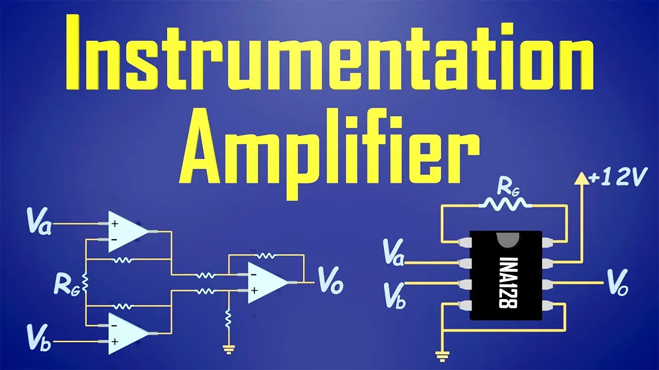



An instrumentation amplifier is a specialized difference amplifier with built-in input buffers that provides high input impedance, low noise, and adjustable gain through resistor RG; its output voltage is derived as Vout = (R3/R2) × [1 + (2R1/RG)] × (V2 - V1), where the gain can be controlled by varying RG, with smaller RG values producing larger gains.
Instrumentation Amplifier Derivation: Op-Amp Circuit Explained
Added:Basic operational amplifier (op-amp) theory, including the ideal op-amp assumptions (infinite input impedance, zero output impedance, and the virtual short/virtual ground concepts).
Analysis of fundamental op-amp configurations, specifically the non-inverting amplifier and the classic four-resistor differential (difference) amplifier.
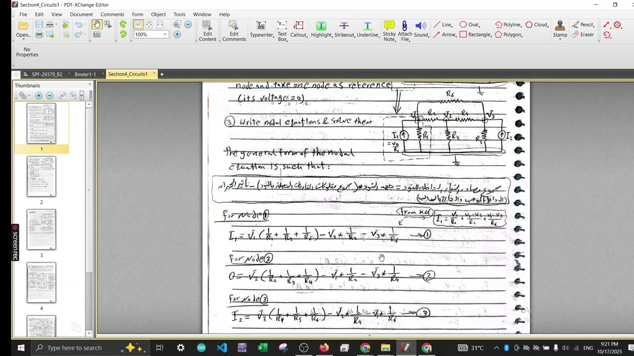
Nodal analysis techniques using Kirchhoff's Current Law (KCL) and Ohm's Law to derive node voltages in multi-stage active circuits.
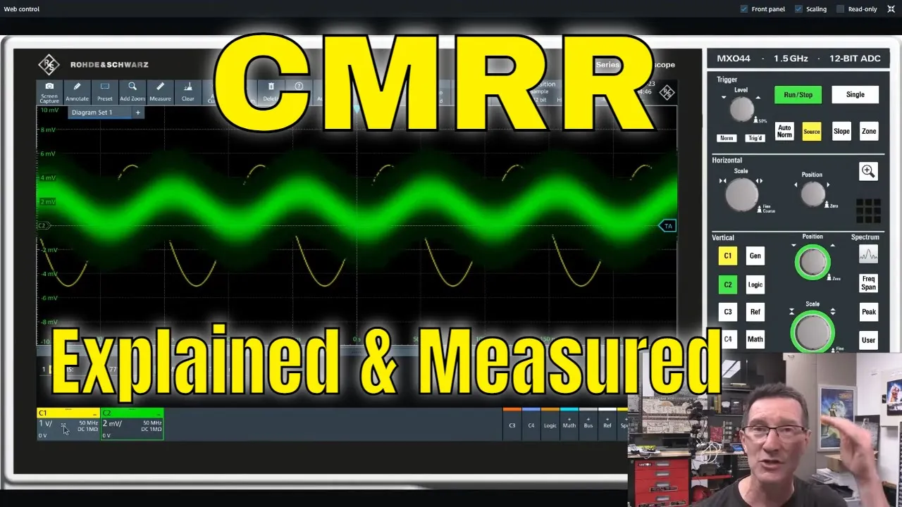
The basic concept of differential-mode signals versus common-mode signals and why electrical noise often appears as a common-mode voltage.
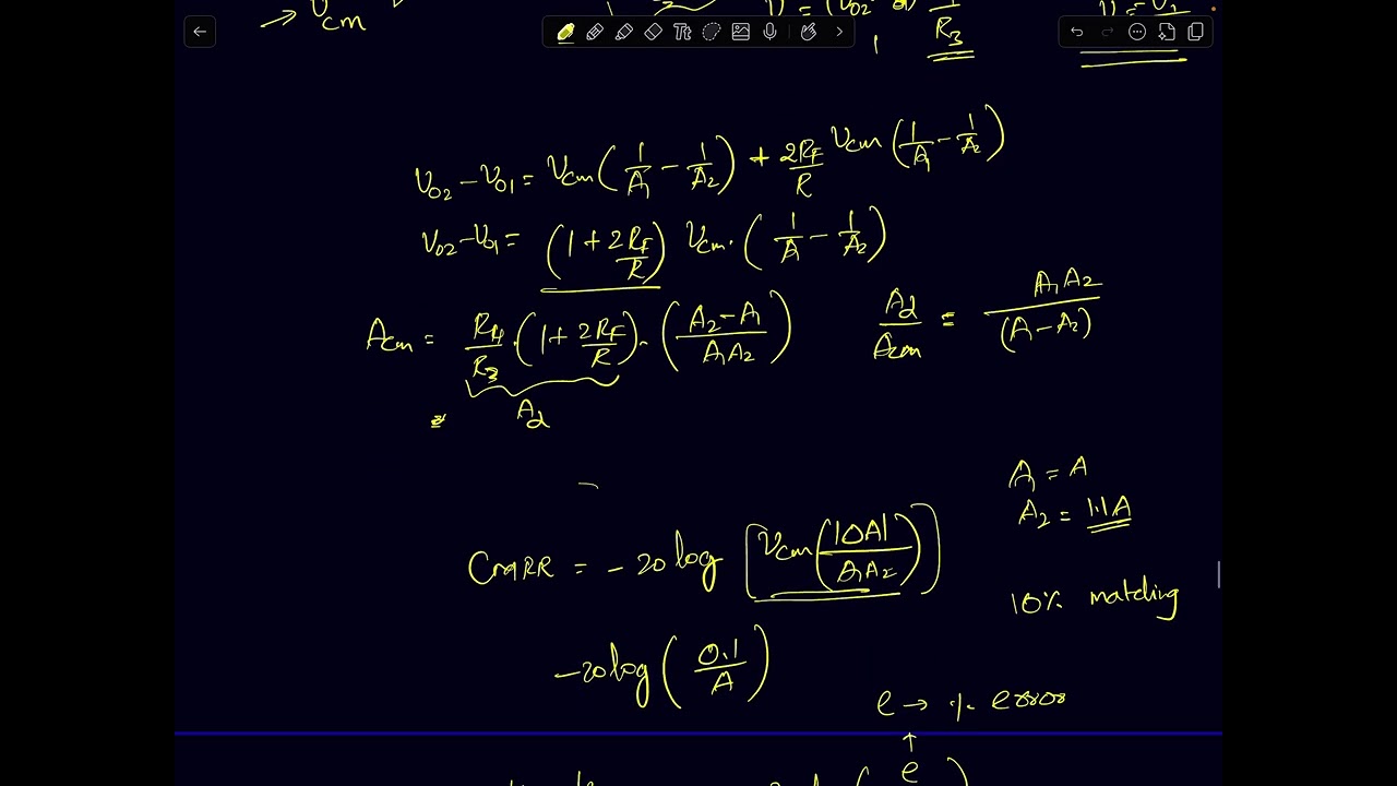
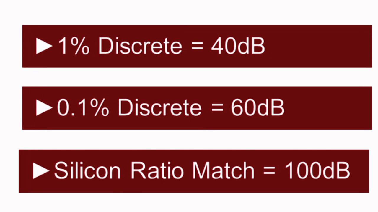
Understanding the Common-Mode Rejection Ratio (CMRR) and calculating how resistor tolerances/mismatches degrade the CMRR of an instrumentation amplifier.
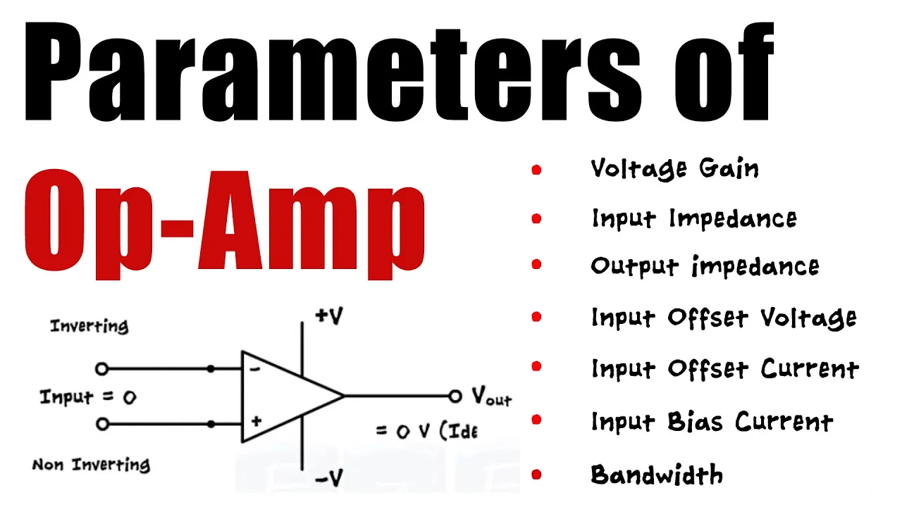
Study of practical non-ideal op-amp characteristics in instrumentation amplifiers, such as input offset voltage, input bias currents, and gain-bandwidth limitations.
Exploration of monolithic (integrated circuit) instrumentation amplifiers, such as the AD620 or INA118, and the role of internal laser-trimmed resistors.
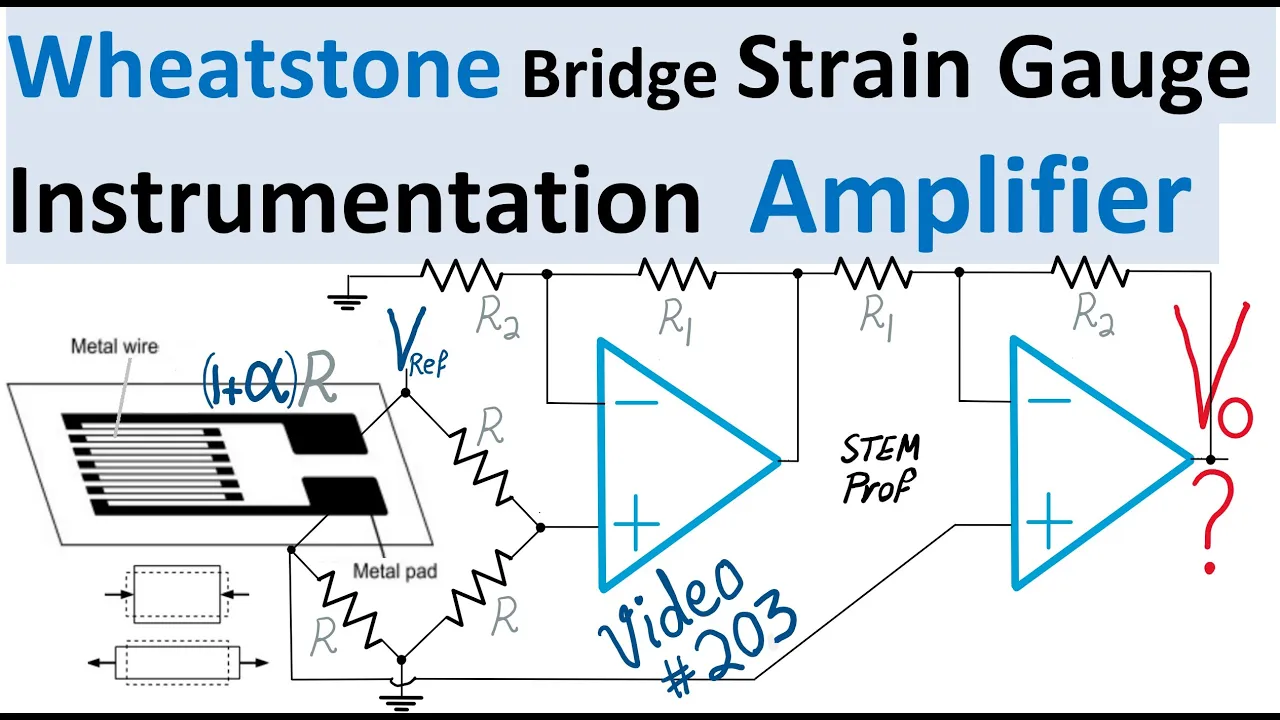
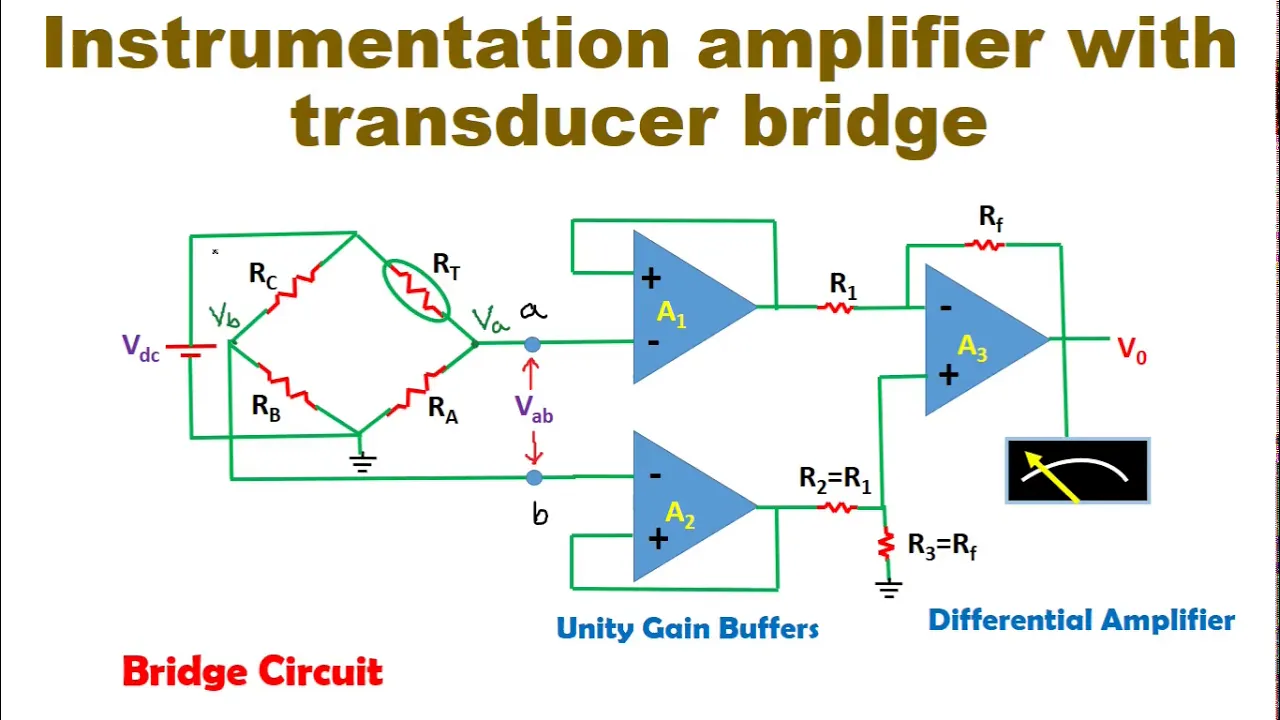
Application of instrumentation amplifiers in low-level sensor signal conditioning, such as Wheatstone bridges, strain gauges, thermocouples, and biomedical acquisition systems (ECG/EEG).
105.5K views881likes13:25Original Release: 2016-06-16
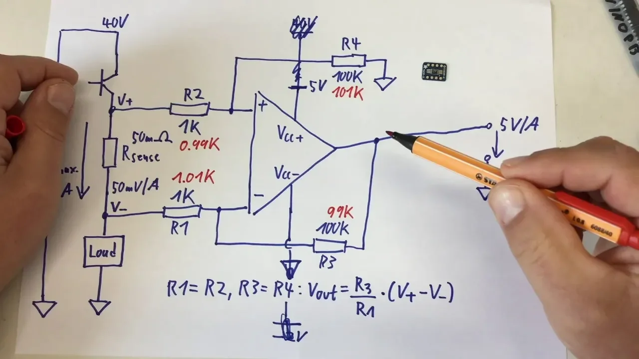
In this video I will talk about operational amplifier instrumentation amplifier and at last I will show you the derivation of equation of output voltage for this instrumentation amplifier circuit. Since long the electronic engineers have been in quest of universal amplifier that may fit in most of the applications without any serious limitations of gain, stability and impedance matching,the instrumentation amplifier fulfills all these requirements. An instrumentation amplifier is a kind of difference amplifier which has inbuilt input buffers see this is a operational amplifier buffer and this is another buffer so it has inbuilt buffers which eliminate the need of input impedance matching the instrumentation amplifier is designed to have a very low DC offset low drift low noise very high open-loop gain and very high common mode rejection ratio and very high input impedance.See as the circuit is a buffer circuit it will have very high input impedance and we can control the gain of the operational amplifier by using this resistor RG. Here this RG means we can control the gain of this amplifier using this resistor Rg. The op amp instrumentation amplifier uses three of em see this is one of em this is another of em and this is another of em and we can divide this op amp instrumentation amplifier into two segments and this is the difference amplifier segment and this is the buffer circuit segment now let me show you the derivation of this operational amplifier instrumentation amplifier see our operational amplifier instrumentation amplifier can be divided into two versions of a circuit unit and difference amplifier unit see the voltage at this point is let us say P oh one and that will be applied at one end of this r2 and the voltage at this end is po2 when we have a difference amplifier like this with voltage at one terminal v01 and with voltage one terminal p02 we can calculate the output voltage by using this formula see this is our output voltage so this will be the output of the difference amplifier or operational amplifier subtractor the O will be equal to r3 divided by r2 into the voltage at this terminal p02 minus the voltage at this terminal e01 let's say this is our equation number one this is the output equation of this difference amplifier if you don't know anything about difference amplifier I will request you to check wipe one of the previous videos regarding this difference amplifier or operational amplifier subtract or circuit okay so this is the output voltage equation let's say this is our equation number one in this unit we have two power circuits see this is one buffer and this is another buffer see at this non-inverting terminal I am applying a voltage p1 and at this non-inverting terminal I am applying a voltage v2 let's say the value of this p1 is greater than v2 now see this output terminal of this op-amp is connected with the inverting terminal through a resistor r1 on this output terminal will be connected with the inverting terminal the circuit this op-amp will be in negative feedback see this output terminal is connected with the inverting terminal through this resistor r1 so this op-amp will also be in negative feedback when an operational amplifier is in negative feedback its inverting terminal voltage and non-inverting terminal voltages will be equal that means V P will be equal to P n see the voltage at this non-inverting terminal is e2 therefore the voltage at the inverting terminal will be p2 the here the non-inverting terminal voltage is v1 therefore the voltage at the non-inverting terminal should be v1 see this is the terminal so the voltage at this terminal will be v1 and see this terminal is connected with this point so the voltage at this terminal will be p2 as the operational amplifiers are in negative feedback therefore the current through the inverting terminal and non-inverting terminal will be 0 that means there will be no current flow through this path or there will be no current flow through this path okay that means as there is no current flow through this path or this path the same current will flow from this vo0 one terminal towards this key zero or two terminal now see I know the voltage at this terminal and this terminal and I have assumed this V 1 is greater than this V 2 therefore if I assume the current through the resistor RG is equal to I R I will be flowing in this indicated direction because P 1 is greater than P 2 that means this terminal will be at higher potential and this terminal will be at lower potential so I can calculate the current I using this formula I will be equal to higher voltage P 1 minus P 2 divided by the resistance R gee let's say this is our equation number 2 okay now see when this I will enter at this point it will have two parts to divide one is in this path and another is through this path see the current in this direction will be equal to zero that means the same current I will flow through the resistor r1 now see if I consider this current I is outgoing from this terminal you will see there will be no current flow through this path because this of mpz negative feedback and when an operational amplifier is in negative feedback inverting terminal current will be zero so as the current through this path is equal to zero that means this current I must be in coming from this direction that means the same current I will flow through the resistor r1 from this terminal towards this terminal now if I assume the voltage at this terminal is equal to p0 1 and the voltage at this terminal is equal to p o2 or p0 - you will this p01 will be at higher potential or this terminal should be positive and this terminal should be negative and current always flows from higher potential towards the lower potential now I know the voltage difference between this point to this point as there is no current flow in this direction or in this direction that means they will act like open circuit now see I know the resistance from this terminal to this terminal which will be the sum of this R 1 RG and this R 1 and the voltage difference between this terminal to this terminal now if I apply Ohm's law I will get the current I Here I am calculating the current from this terminal to this terminal see as current is flowing from this direction so this terminal will be at higher potential and this terminal will be at a lower potential now I am applying Oh homes law Ohm's law states that current will be equal to the voltage difference divided by total resistance of that path here you will see the voltage difference will be v01 minus v02 you and the total resistance from this terminal to this terminal will be equal to r1 plus RG plus r 1 r 1 plus r g plus R 1 from which I can write P 0 1 minus p 0 2 divided by 2 R 1 plus R G see from Equation 2 I can write I equal to P 1 minus P 2 divided by RG now let me put the value of I 2 which I have obtained from equation number 2 P 1 minus P 2 divided by the value of gain resistance so here I write V 0 1 minus p 0 2 equal to 2 R 1 plus R G divided by R G into T 1 minus P - now see to calculate the output voltage I have to take po2 or p02 minus v01 so if I take a minus sign in front of both sides I will get P 2 minus P 1 equal to C I can simplify it like this 1 plus 2 R 1 divided by R T into P 2 minus P 1 let's say this is our equation number 3 see from Equation 1 I can write your output voltage will be equal to R 3 divided by R 2 into p0 2 minus v01 now let me put the value of p0 2 minus p0 1 from the equation number 3 taeo equal to R 3 divided by R 2 into 1 plus 2 R 1 divided by R G into V 2 minus V 1 see this is the output voltage equation of our instrumentation amplifier now I will calculate the gain of instrumentation amplifier see this is the differential input voltage and this is the output voltage so if I take the ratio of output voltage and differential input voltage p2 minus p1 I will get the gain of this instrumentation amplifier which will be equal to r3 by r2 into 1 plus 2 R 1 by r g so this is the gain equation of the instrumentation amplifier usually the RG is a variable resistor if I make this RG smaller I will get a very large gain if I increase the value of this RG I will get a very smaller again okay that's it thank you
Up Next
6:54
Active Low Pass Filter Design with Op Amps
@KelvinLeUT
47.1K views•2014-04-14

30:32
Ultrasonic Transducers: Resonant Frequency Measurement and Horn Design
@imajeenyus42
229.9K views•2017-02-22

54:16
Polymer Environmental Degradation: Mechanisms & Stabilization
@iit
1.8K views•2012-07-10

33:39
How a Student's Question Saved a NYC Skyscraper from Collapse
@veritasium
22.8M views•2025-04-26
Related Study Plans & Knowledge Roadmaps
Structured learning paths in Engineering
engineering
Building Acoustic Levitators: Physics & Arduino
01The Physics of Sound and Standing Waves
02Piezoelectric Transducers and H-Bridge Drivers
03Arduino Programming: Generating 40 kHz Signals
+ 2 more learning modules
14h5 modules
Explore Roadmap
engineering
Building Peltier Cloud Chambers: Particle Tracks
01Cosmic Rays & Cloud Chamber Physics
02Thermoelectric Cooling (TEC) Fundamentals
03Custom Liquid-Cooling Loop Design
+ 2 more learning modules
18h5 modules
Explore Roadmap
engineering
Yagi-Uda Antennas: Modeling, Build & VNA Test
01Introduction to RF and Antenna Fundamentals
02Yagi-Uda Antenna Design Principles
03Antenna Modeling and Simulation in 4NEC2
+ 2 more learning modules
18h5 modules
Explore Roadmap
engineering
ECG Monitor Design: Op-Amps, Filters & Noise
01Electronics & Breadboard Basics
02Op-Amps and Instrumentation Amplifiers
03Bioelectricity and ECG Fundamentals
+ 2 more learning modules
18h5 modules
Explore Roadmap