










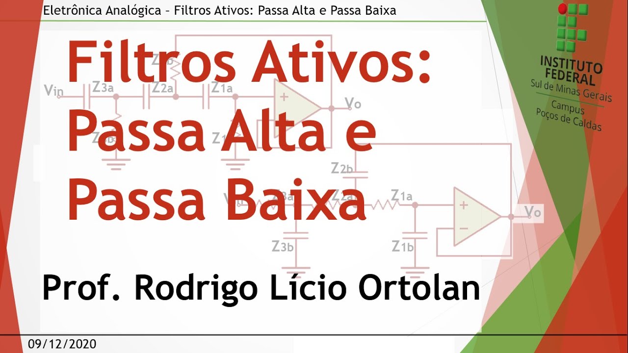






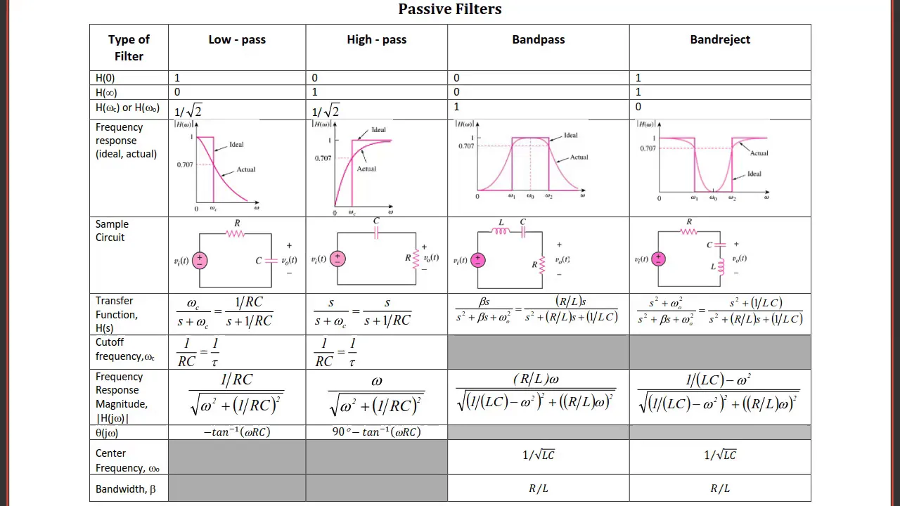
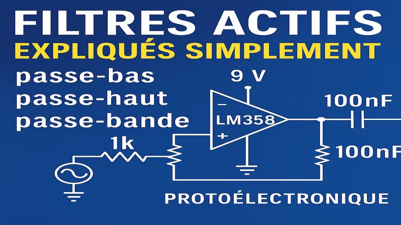
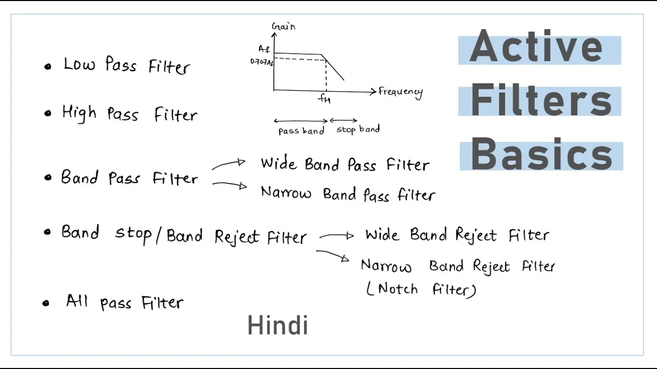
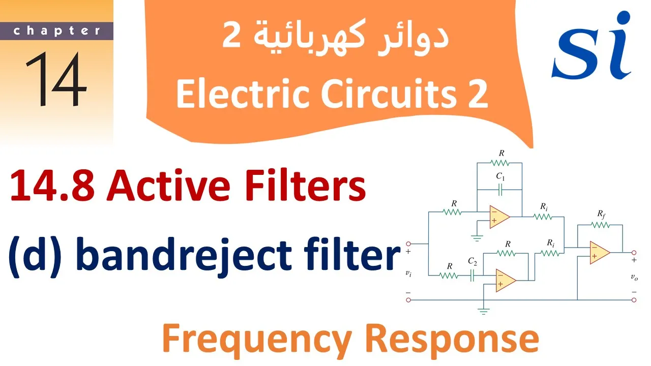


An active low pass filter using an operational amplifier consists of two resistors (R1, R2) and one capacitor, with its transfer function given by H(s) = -R2/R1 × 1/(1 + sR2C), where the pole frequency ωp = 1/(R2C); for practical implementation, resistor values should be in the 1kΩ to 10kΩ range and capacitors should use COG/NPO types for temperature stability, while keeping the design simple to minimize noise and parasitics at high frequencies.
Active Low Pass Filter Design with Op Amps
Added:Fundamentals of Operational Amplifiers (Op-Amps), including inverting and non-inverting amplifier configurations.
Basic passive RC (Resistor-Capacitor) circuit analysis and the concept of cutoff frequency.
AC circuit analysis techniques, including complex impedance and phasor domain representation.
Introduction to transfer functions and how to interpret frequency response plots (Bode plots).
Design of higher-order active filters, such as second-order Sallen-Key and Multiple Feedback (MFB) topologies.
Study of filter response types, including Butterworth (maximally flat), Chebyshev (steep roll-off), and Bessel (linear phase) approximations.
Implementation of other active filter configurations, such as high-pass, band-pass, and band-reject (notch) filters.
Analysis of practical op-amp non-idealities, including Gain-Bandwidth Product (GBP) limitations, slew rate, and component tolerance sensitivity.
47.1K views185likes6:54Original Release: 2014-04-14
Hey, what's going on everyone? In this video, we'll go over the active low pass filter and how to implement a low pass filter in a real design. So, let's first go over the trans function of a uh single pole lowass filter using op amp, a single op amp.
So you have two resistors and one cap that sets the uh low frequency pole the fre the low pass frequency. So this is R that's R V in V out uh R1 R2.
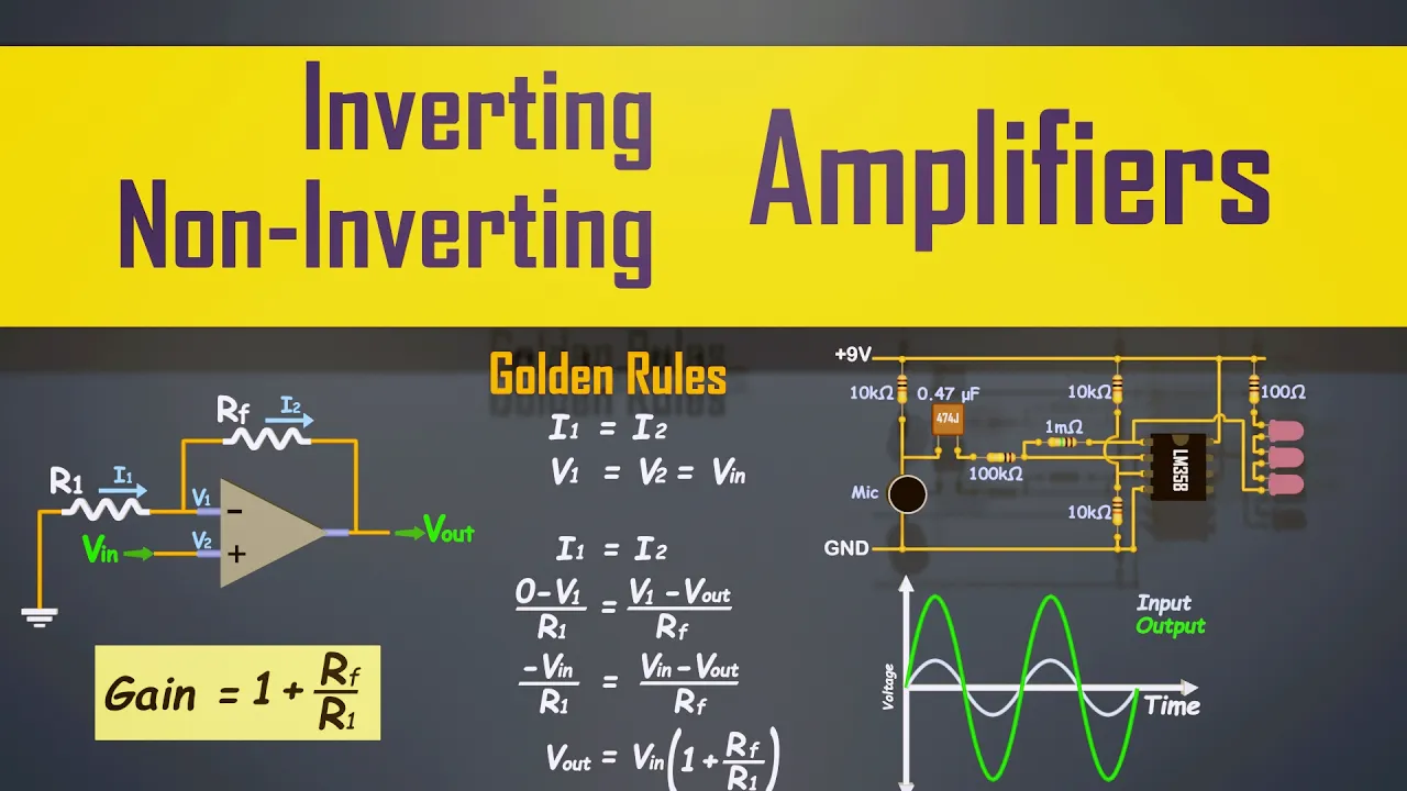
So the trans function is V out over VN.
And if you do the KCL you get um minus ZF over ZN, right? Because this ZF is the feedback and this is this is ZN which equals to minus R par with one over SC over ZN which is just R R1 is R2.
All right.
Now R2 in parallel with one / SC is equals to if you do in terms of emittance which is 1 / R2 + J. Why did I do J? Um we're sticking with S for now.
It's easier.
We can always plug it back in. So that's this is impedance still inside is emittance that gives you R2 1 + S R2C.
So this is ZF right now the trans function let's define this as H.
H now is equal to minus R2 over 1 + SR2 C over R1.
And now uh this you're not done here.
You have to simplify this. So you factor out - R2 / R1* 1 / 1 + S R2 C. Now the pole uh omega omega p is equal to 1 / r2 c.
So the pole is just set by these two combination. Okay.
These okay okay so the now we have the equation. Let's talk about um real life implementation.
Well, sometimes you want to use a bias resistor and you have to add a bio resistor.
That's assuming you have a lot of bias current.
I mean, um, ideally you don't want to use any bias resistor, but if you have to, then the R is just R bias equal to R1 parallel with R2. And some of you might wonder why not consider C.
Remember that the bias current IB is at DC. So at DC this is an open. So all you have is just the impedance looking out here and looking out here. So these two are in parallel because here is a short because this is a voltage source and here is a voltage source. You short it.
So impedance looking out it's just R1 in parallel R2 gives you RV. All right. So in real life um if you want to do high speed low noise I recommend using R uh any either R1 or R2 in the range from 1 kiloohm to 10k.
I mean if you if you increase the the frequency uh I mean if the speed is really fast you might even want to consider lowering this resistor value low because at high high speed you have a lot of parasitics and OPM works a lot better when you have low resistant values in this range uh for a capacitor you know the range can go from 100 poparad to uh these are common values 100 nanofarad and the reason why I'm I wrote down these values is because uh if you want to create a temperature stable opamp low pass filter these are the values that actually you can get cog uh capacitor which is temperature the best temperature uh coefficient you can get for capacitors or np0 uh these are equivalent.
So that's a real life uh consideration you have to uh note.
So you know for capacitor values in this range it can get expensive.
Um yeah just check it out on mouser and you you'll see what I mean when you trying to find these cog capacitors.
So um for a capacitor highet you know you can get X 7R X5R that's the next um best thing you can do if you can't do COG or NPO these are like 20% uh temperature variation over range this one is like less than 5% or even better okay um yeah so yeah in a real um design.
These are you know I mean this circuit works for a lot of things and um and the one thing that I've learned from just experience is that you want to keep things as simple as possible if you want to do really good design.
So you know uh a fancy uh some kind of fancy design wouldn't wouldn't probably work at high high frequency. So at high frequencies you want to keep everything simple you know low few the fewest component as possible to reduce noise parasitics and yeah that's that's something you just have to do and learn with uh with time.
All right uh I guess I'll conclude this video. Uh thanks for watching. Uh let me know what you think. See you next time.
Up Next

24:44
ECG Schematic Design: 3-Lead Dual Supply Front End
@jpdieffe
30.8K views•2014-04-27

30:32
Ultrasonic Transducers: Resonant Frequency Measurement and Horn Design
@imajeenyus42
229.9K views•2017-02-22

54:16
Polymer Environmental Degradation: Mechanisms & Stabilization
@iit
1.8K views•2012-07-10

33:39
How a Student's Question Saved a NYC Skyscraper from Collapse
@veritasium
22.8M views•2025-04-26
Related Study Plans & Knowledge Roadmaps
Structured learning paths in Engineering
engineering
Building Acoustic Levitators: Physics & Arduino
01The Physics of Sound and Standing Waves
02Piezoelectric Transducers and H-Bridge Drivers
03Arduino Programming: Generating 40 kHz Signals
+ 2 more learning modules
14h5 modules
Explore Roadmap
engineering
Building Peltier Cloud Chambers: Particle Tracks
01Cosmic Rays & Cloud Chamber Physics
02Thermoelectric Cooling (TEC) Fundamentals
03Custom Liquid-Cooling Loop Design
+ 2 more learning modules
18h5 modules
Explore Roadmap
engineering
Yagi-Uda Antennas: Modeling, Build & VNA Test
01Introduction to RF and Antenna Fundamentals
02Yagi-Uda Antenna Design Principles
03Antenna Modeling and Simulation in 4NEC2
+ 2 more learning modules
18h5 modules
Explore Roadmap
engineering
ECG Monitor Design: Op-Amps, Filters & Noise
01Electronics & Breadboard Basics
02Op-Amps and Instrumentation Amplifiers
03Bioelectricity and ECG Fundamentals
+ 2 more learning modules
18h5 modules
Explore Roadmap