



![Funkmodul - Arduino Tutorial (Allgemeines, Verkabelung, Code & mehr) [1080p Full HD - german]](https://i.ytimg.com/vi/MbTIvael6yI/hqdefault.jpg)






![[۱۸] دورهی آموزشی میکروکنترلر STM32: راهاندازی پروتکل ارتباطی UART و معرفی گیرندههای GPS](https://i.ytimg.com/vi_webp/JbsJJ_TXqJE/maxresdefault.webp)




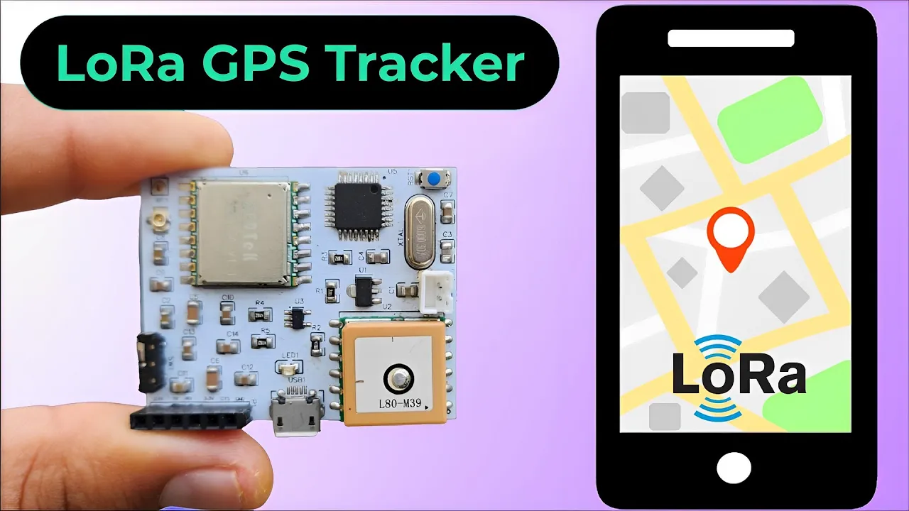
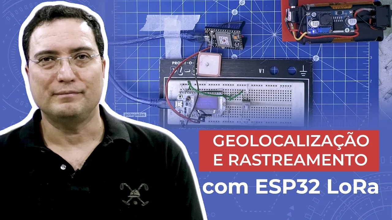




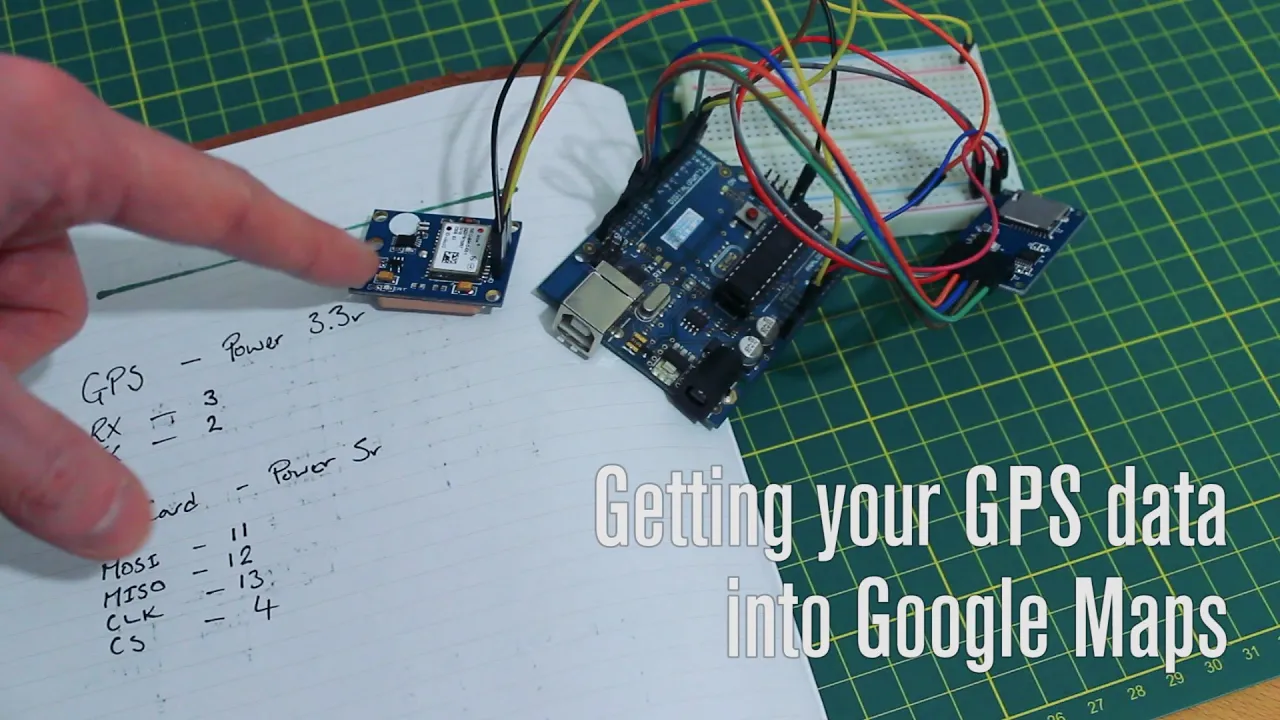



This tutorial demonstrates how to connect a U-blox Neo-6M GPS module to an Arduino board using UART communication (VCC to 5V, RX to pin 3, TX to pin 4, GND to GND), and explains the process of installing the TinyGPS library in Arduino IDE to read GPS coordinates, noting that GPS signals cannot be received indoors and require outdoor testing for successful operation.
Connect & Use NEO-6M GPS Module with Arduino: Tutorial
Added:Basic Arduino programming, including uploading sketches and installing third-party libraries via the Library Manager.
Fundamentals of serial communication (UART), specifically how RX and TX pins function and the concept of SoftwareSerial.
Basic electronics prototyping, including wiring VCC, GND, and data lines on a breadboard, and understanding voltage levels.
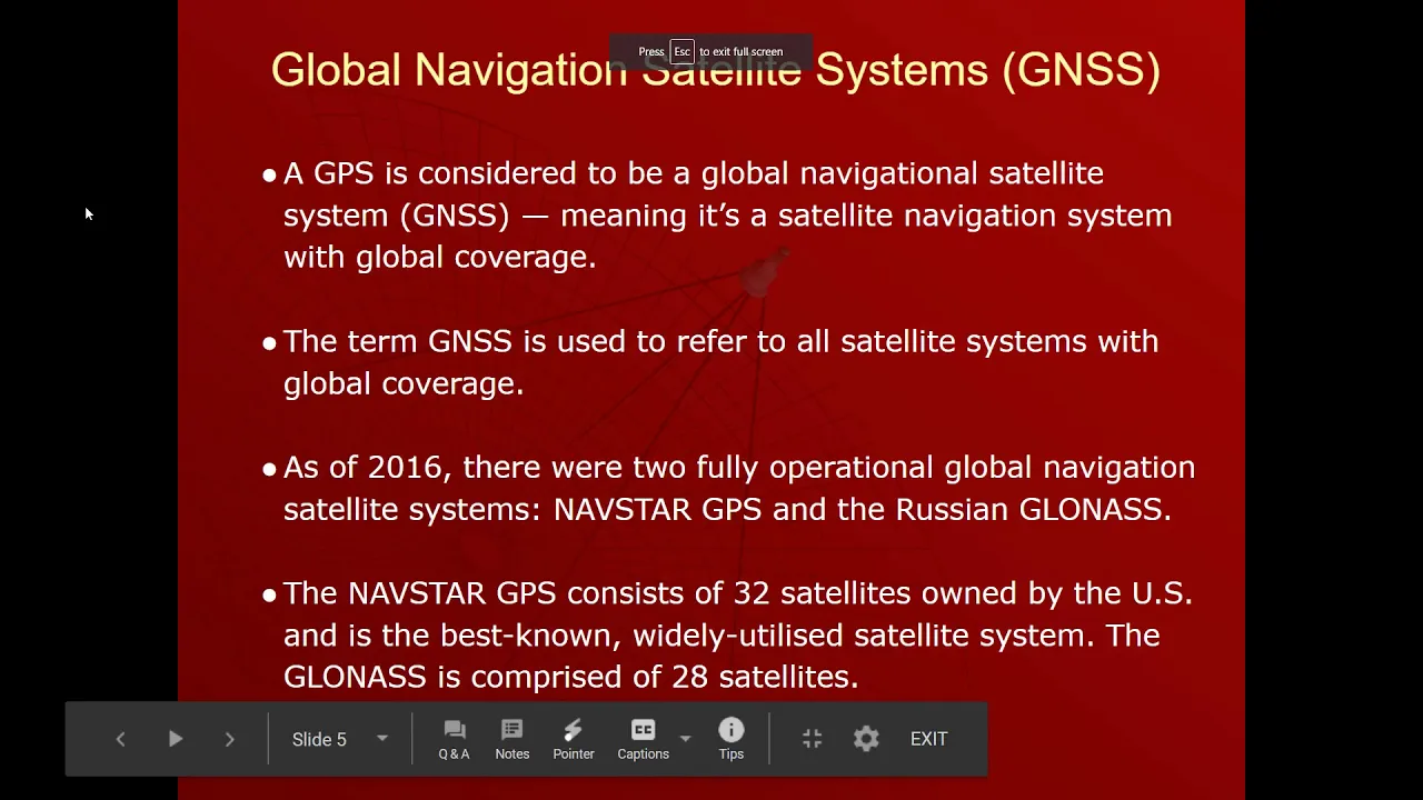
An elementary understanding of how GPS technology works, including satellite trilateration and the necessity of outdoor line-of-sight for signal acquisition.
Parsing raw NMEA sentences ($GPRMC, $GPGGA) to extract custom telemetry data without relying solely on basic libraries.
Developing an autonomous GPS data logger by integrating an SD card module to record coordinate history over time.
Combining the GPS module with cellular (GSM/GPRS) or LoRa modules to build a real-time wireless asset tracking system.
Integrating the parsed GPS data with web-based mapping APIs (such as Google Maps or Leaflet) to visually plot tracked paths.
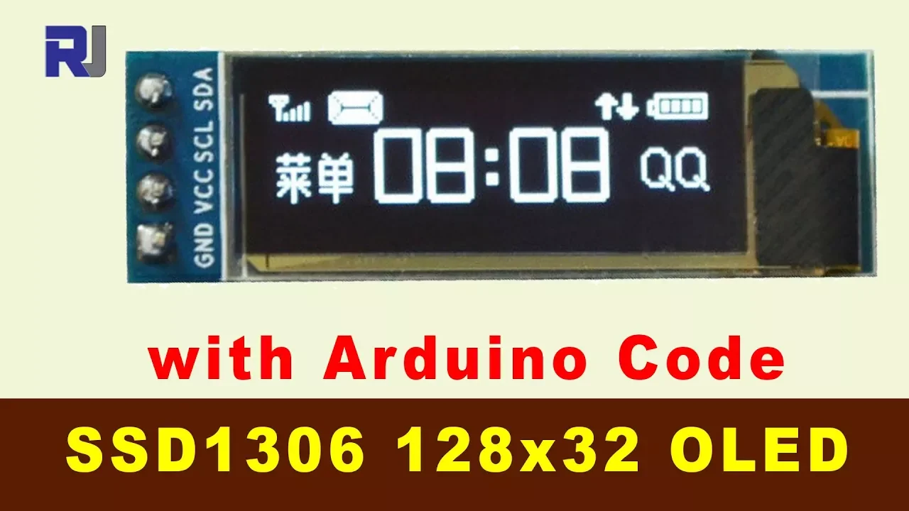
Interfacing the system with an I2C OLED or LCD display to show real-time velocity, altitude, and coordinate data on a portable device.
10.8K views88likes4:26Original Release: 2024-08-26
Hello, this is Junhyuk Lee from Saeronshak.
In this session, we will be using a GPS module that can be connected to an Arduino.
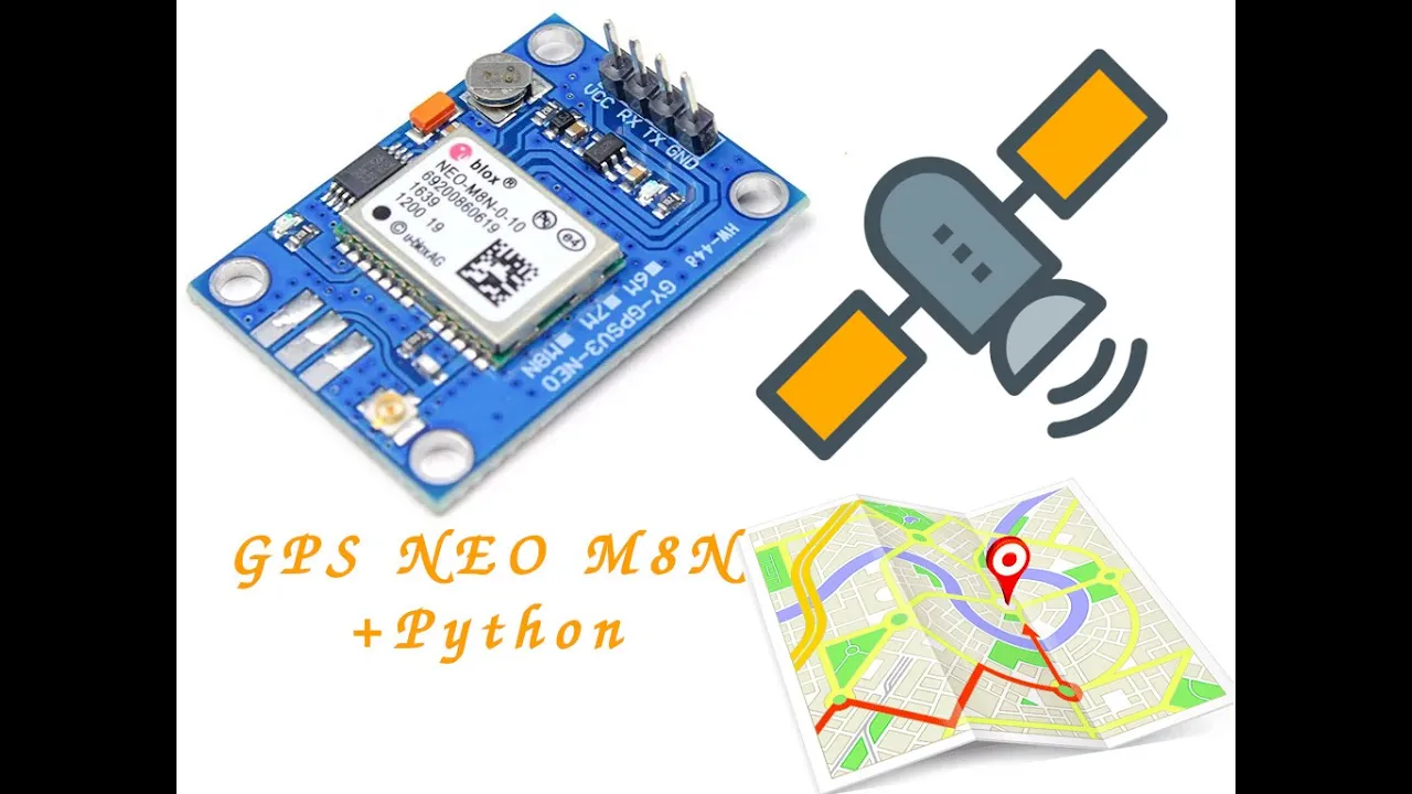
Among the GPS modules, we will be using UBLUX 's Neo6M GPS module.
What you see on the screen is the Neo6M GPS module, and you can purchase it from Device Mart through the link below.
Let 's go ahead and connect this GPS module to the Arduino and control it.
What you see here is UBLUX 's Neo6M GPS module.
This GPS module is controlled using MCO and UART communication.
So, if you look at the pins, you will see that VCC, RX TX, and GND are indicated like this.
We will connect RX to pin 3 on the Arduino board, TX to pin 4 on the Arduino board, VCC to the 5V pin on the Arduino board, and GND to the GND pin on the Arduino board.
We will use male-female jumper wires to make the necessary connections between the components.
First, connect VCC to the 5V pin on the Arduino board, then RX to pin 3 on the Arduino board, and finally TX to pin 4 on the Arduino board.
Additionally, ensure that all connections are secure and double-check each connection to avoid any potential issues during operation.
Finally, carefully establish a connection from the ground to the ground on the Arduino like this… Let 's write some Arduino code and see if it works properly.
While connected to the Arduino, please simply run the Arduino IDE.
After running the Arduino IDE, you will see the Library Manager under the Tools menu.
Click on this, and when the Library Manager appears, search for Tiny GPS.
Then, one rival will appear in the search results.
Click on it to install.
Once you click, it will be installed.
Then close it, and next, in the file, there is an example for Tiny GPS to the file for better understanding and clarity.
Please click on Simple Test here… Instead of just running it as is, we will make some modifications.
First, simply copy the entire content, and then paste it here… Close this, and then what we connected earlier was the TX and RX to the pin numbers specified in the code, which are 4 and 3.
The serial.begin part is the baud rate speed for UART communication between the computer and the Arduino.
The Software Serial communication speed is set to 4800 but the default baud rate speed is 9600.
Please change it to 9600.
Next, in the pool, I have the board and Arduino set up correctly and securely, and I will try uploading it to the board.
When you open the Serial Monitor, you will see that it works like this, but the main problem is that it can not read the GPS coordinates.
This is mainly because the environment I am testing in is indoors, and you can not receive GPS signals indoors at all.
I will go outside and try to run it there.
When you run it outside, you can clearly see the latitude, and longitude displayed at the beginning.
This time, we have successfully controlled the GPS module.
I will introduce another interesting product next time.
See you then, and take care!
Up Next

3:04
Setting a Winch Servo for RC Sailboats: A Step-by-Step Guide
@venturesrcs
6.8K views•2022-08-28

178:38
Whole Brain Architecture: First International Workshop 2024
@thewholebrainarchitecturei9784
640 views•2024-07-22

9:49
FastAPI vs Flask vs Django: Choosing the Right Python Web Framework
@TechWithTim
302.5K views•2024-05-26

1:42
Game of Thrones Opening Credits: A Cinematic Analysis
@gameofthrones
46.3M views•2011-04-18
Related Study Plans & Knowledge Roadmaps
Structured learning paths in General & Interdisciplinary Studies
general-studies
Artificial Light: History, Tech & Human Impact
01The Pre-Electric Era: Fire, Oil, and Gas Lighting
02The Incandescent Revolution and Grid Electrification
03Gas Discharge and Fluorescent Illumination
+ 3 more learning modules
14h6 modules
Explore Roadmap
general-studies
Elevator Engineering: History, Physics & Cities
01From Hoists to Safety Brakes: The Dawn of Vertical Lift
02Hydraulic vs. Traction: The Engineering Physics of Elevators
03Modern Speed, Safety, and Algorithms
+ 2 more learning modules
12h5 modules
Explore Roadmap
general-studies
Rubber: Material Science, History & Geopolitics
01Origins of Natural Rubber & Mesoamerican History
02The Chemistry of Natural Rubber & Vulcanization
03The Geopolitics of the Rubber Boom & Colonization
+ 2 more learning modules
12h5 modules
Explore Roadmap
general-studies
Containerization: Evolution, Logistics & Trade
01Ancient Trade & Bulk Cargo: Amphorae to Barrels
02The Industrial Revolution & Cardboard Packaging
03The Containerization Revolution: Malcom McLean
+ 2 more learning modules
12h5 modules
Explore Roadmap