To properly set up a winch servo on an RC sailboat, place the servo as low as possible to avoid interference, use a square ruler to position the winch line exit correctly, route lines through rollers for smooth movement, and ensure the lines don't touch any boat areas to prevent the sails from getting stuck.
Setting a Winch Servo for RC Sailboats: A Step-by-Step Guide
Added:Deep Dive
Basic anatomy of an RC sailboat, including the mast, boom, rudder, and the functions of main and jib sheets.

Sailboat vocab walk around
363
A sailboat consists of multiple interconnected systems. The cockpit contains lockers for storage, steering equipment (tiller, rudder), safety gear (lifelines, stansions, stern pulpit, flotation devices), and mechanical controls (winches, cleats). The hull features the cabin top, companion way, mast, boom, and bow pulpit. Rigging is divided into standing rigging (fixed support wires: shrouds, forestay, backstay) and running rigging (moving lines: halyards, sheets, outhole, boom vang). The jib is the forward sail with jib sheets, while the main sail is controlled by the main sheet and main halyard. A wind indicator at the mast top shows wind direction.
Click to watch →

Anatomy of a Sailboat
1.6K
A sailboat consists of several interconnected systems: the cockpit contains storage lockers, lifelines with pelican clips for safety, and winches with mechanical advantage for controlling sails; the standing rigging (shrouds, spreaders, forestay, backstay) keeps the mast upright, while running rigging (sheets, travelers, vangs) controls sail position and shape; the jib and main sails are controlled by sheets that run through pulleys and blocks, with travelers and vangs adjusting sail trim for different wind conditions.
Click to watch →
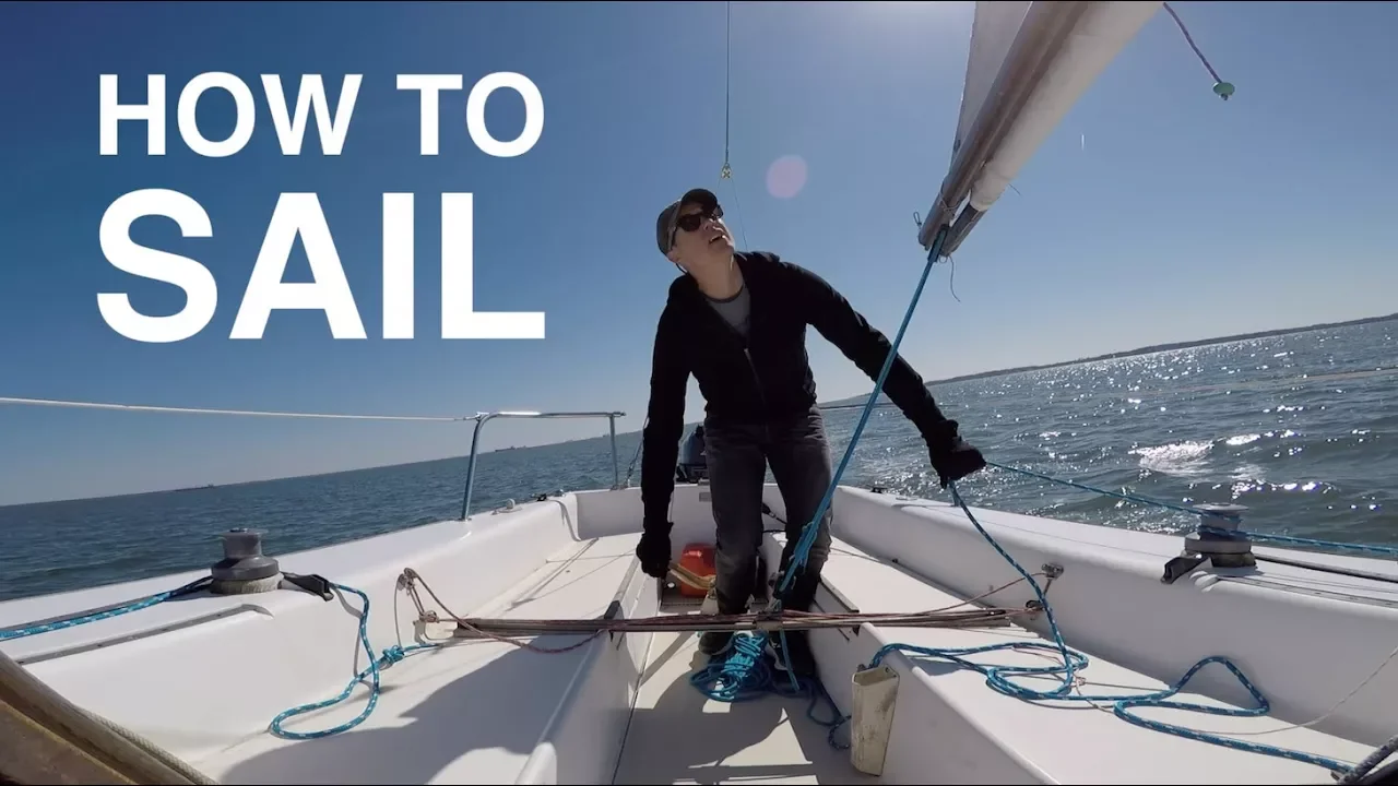
How to Sail: Step-by-Step Basics of Sailing for Beginners
4.1M
Mastering sailboat terminology is essential for safe operation. The tiller controls the rudder beneath the hull for steering. The mast supports the sail structure while the boom holds the mainsail. Sheets (ropes) control sail angle: the main sheet for the mainsail and jib sheet for the head sail. Winches provide mechanical advantage for tensioning sheets. Rigging includes backstays (supporting mast rear), shrouds (side support), and forestays (front support). Head sails range from 100% jibs (triangular) to larger genoas. Three line types serve distinct functions: halyards raise sails, sheets control angle, and dock lines secure the boat. This comprehensive vocabulary enables clear communication and safe sail handling.
Click to watch →

Sailboat Parts Explained: Overview and Names
95.1K
The main mast is the long standing pole in the center of the boat. Attached to the mast horizontally is the boom, to which the main sail is attached. The most front sail is regularly called the jib. This configuration is standard across most sailboat designs.
Click to watch →
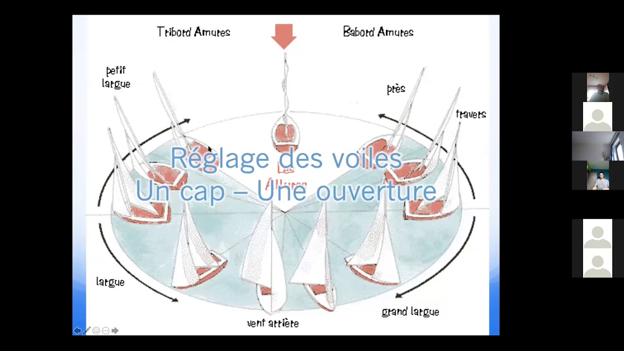
cours RCAE voile : Le réglage des voiles
5.7K
This section covers the fundamental components of a sailboat's rigging system. The main components include the mast (mât), mainsail (grand voile), jib (phoque), and spinnaker (spi). The mainsail has one sheet (écoute), while the jib and spinnaker each have two sheets. A sail has three key points: the tack (point de risso) at the bottom with a reinforced tack plate (têtière), the clew (point des côtes) at the rear, and the luff (point d'un mur) at the front where the sail attaches to the mast. Each side of the sail has specific names: the leech (gain) is the front edge, reinforced to pass through the mast track, the clew (chute) is the rear upper edge, and the bottom edge is called the bottom (bordure). The sail control system uses sheets (écoutes) passing through blocks (poulies), with the complete system called a tackle (palan). With two blocks, force is divided by two; with four blocks, force is divided by four, making sail control easier.
Click to watch →
Deep Dive
Understanding the mechanical differences between standard positional servos and multi-turn winch (drum) servos.

Drinks and Droids - Dome internal
839
Servo technology offers multiple approaches for droid mechanisms. Multi-turn servos (5-turn models) provide precise positioning over extended ranges without limit switches, ideal for chopper head arms. Standard servos with end stops require code to monitor switch states. Stepper motors offer precise control but require additional drivers and programming. Servos simplify implementation with Maestro controllers, save space, and reduce complexity. The choice depends on specific requirements for precision, space, and ease of implementation.
Click to watch →

Multi-turn servo
2K
A multi-turn servo is a type of servo motor designed to rotate over more than 360 degrees, allowing for extended angular range of motion beyond traditional single-turn servos; this demonstration shows a servo achieving 720 degrees of rotation by continuously turning from left to right and back to center multiple times.
Click to watch →
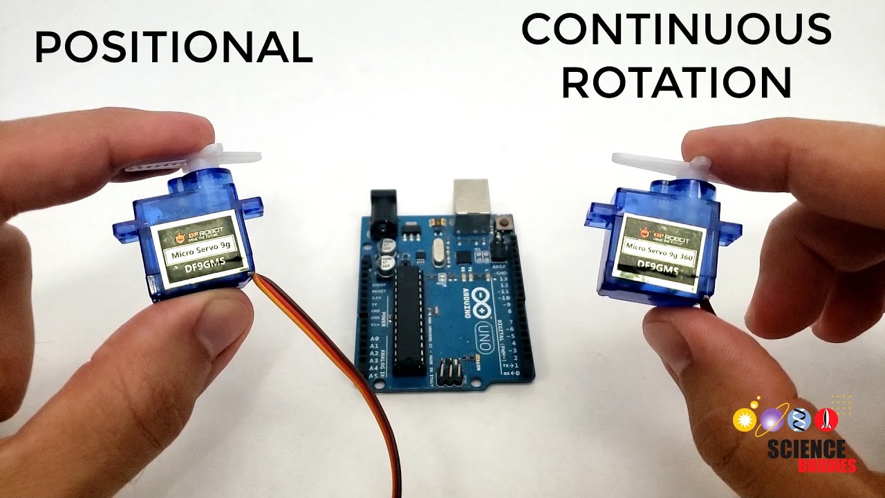
Positional vs Continuous Rotation Servo Motors
132.1K
Positional and continuous rotation servo motors appear nearly identical but serve fundamentally different purposes. Positional servos rotate approximately 180 degrees (typically 160-170 degrees in practice) and use the 0-180 value range to control angular position - sending 90 centers the servo. Continuous rotation servos perform multiple complete rotations and interpret the same 0-180 range as speed: 0 means full speed clockwise, 180 means full speed counterclockwise, and 90 stops the motor. Students often confuse these because they look the same and use similar control methods, but their internal mechanisms and interpretation of control signals differ completely.
Click to watch →

F-35B | Making The World’s Biggest RC STOVL Jet Model Part.2 Ramy RC - how to build a F-35B 3BSM
62.6K
Specialized servos used in advanced RC models feature four wires instead of the standard three, with the fourth wire providing feedback pulses for position sensing. This enables multi-turn operation where the servo can rotate beyond its normal 60-degree range. High-torque servos like the MD 89 M are required to handle the demanding loads of large-scale RC aircraft control surfaces.
Click to watch →

W5513-6T Servo Demonstration
190
The W5513-6T is a multi-turn servo motor designed for RC sailboats, featuring a 6-turn rotation capability (approximately 8 turns from 800-2200 microseconds), 10.63 kg-cm stall torque at 6V, and all-metal gears with bearings for durability; it can be adapted for linear motion applications by wrapping string through its drum holes, with current draw ranging from 80mA idle to nearly 0.5A under load.
Click to watch →
Deep Dive
Fundamental physics of friction, tension, and line routing, and how they affect mechanical efficiency in rigging.

Advanced Arborist Rigging Theory Webinar with Taylor Hamel - TreeStuff
21.2K
Mechanical advantage in rigging systems is calculated as the ratio of output force to input force, determined by counting the rope legs at the moving block (e.g., 3 legs = 3:1 ideal mechanical advantage). Friction significantly affects system efficiency, with natural forks and carabiners typically creating about 50% friction, while high-efficiency pulleys reduce this to approximately 13%. The direction of rope angles dramatically impacts anchor point forces: at 90 degrees, a 100-pound load creates about 141 pounds of peak force, but at 170 degrees, the same load creates nearly 600 pounds of tension. When rigging, the most efficient pulley should be placed closest to the input force to maximize output, and vectoring a tensioned line can dramatically increase force for applications like pulling trees over or tensioning porter wraps.
Click to watch →
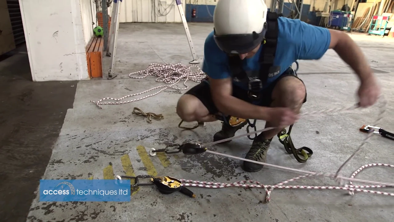
Rigging Tension Lines for rope access
167.3K
When rigging tension lines for rope access, it is essential to equalize the load across multiple anchors by creating a bunny (rope loop) tied with a figure 9 knot and clipped to both anchors, then applying only hand-tight tension rather than excessive mechanical advantage, as ID devices automatically slip at approximately 6kN to prevent system overload.
Click to watch →

8.01x - Lect 25 - Static Equilibrium, Stability, Rope Warker
159.3K
Wrapping a rope around a pole allows a small force to balance or control a much larger force through friction. The relationship between tensions on either side of the rope is given by T2/T1 = e^(μθ₀), where θ₀ is the total contact angle in radians and μ is the coefficient of static friction. This mechanical advantage depends exponentially on both the friction coefficient and the contact angle, independent of the pole's radius. More turns or higher friction provides greater mechanical advantage.
Click to watch →

Consistent, Portable Friction for Rigging | How to set up and use Notch Portawrap | Beginner Rigging
83.9K
A Notch Portawrap is a metal bollard device used in tree rigging to provide consistent, portable friction for lowering heavyweights without damaging ropes against tree trunks; proper setup involves tying the sling eye around the long portion of the device, wrapping the rope around the tree with a timber hitch (typically 5-6 wraps), and taking controlled wraps (half, one, or two wraps) around the bollard while using the 'sweating the line' technique to remove slack before verifying sufficient friction and ensuring the climber is ready before releasing the piece.
Click to watch →

Mechanical Advantages: Counting Tensions & Estimating System Efficiency Part 2
35.6K
Mechanical advantage calculations assume no friction, but real systems lose efficiency through pulley friction. Pulley efficiency depends on construction (bushing vs sealed bearings) and materials. High-efficiency pulleys reach ~90%, while aluminum carabiners are ~45% efficient, and descent devices like Grigrees are ~28%. Theoretical MA values (2:1, 3:1, 4:1) are never achieved in practice. Understanding these efficiency ratings is essential for accurate system design and performance prediction.
Click to watch →
Deep Dive
Familiarity with basic rigging components such as fairleads, blocks (pulleys), and tensioning bows.

Theatrical Rigging Basic Terms to Know!
19.9K
Pulleys (blocks) change force direction using grooved wheels called sheaves. Head blocks receive rope from riggers, while loft blocks sit above loads. Spot blocks move freely for flexible setups; mule blocks redirect lines without bearing weight. Tension blocks adjust force on stage floors. The grid holds all rigging via metal pipes. Tie-off points secure loads when not in use, with cleats (resembling bull horns) and pin rails common in hemp systems. Counterweight systems use lock rails instead of tying off due to continuous loops. Line sets are numbered for identifying which components operate together.
Click to watch →
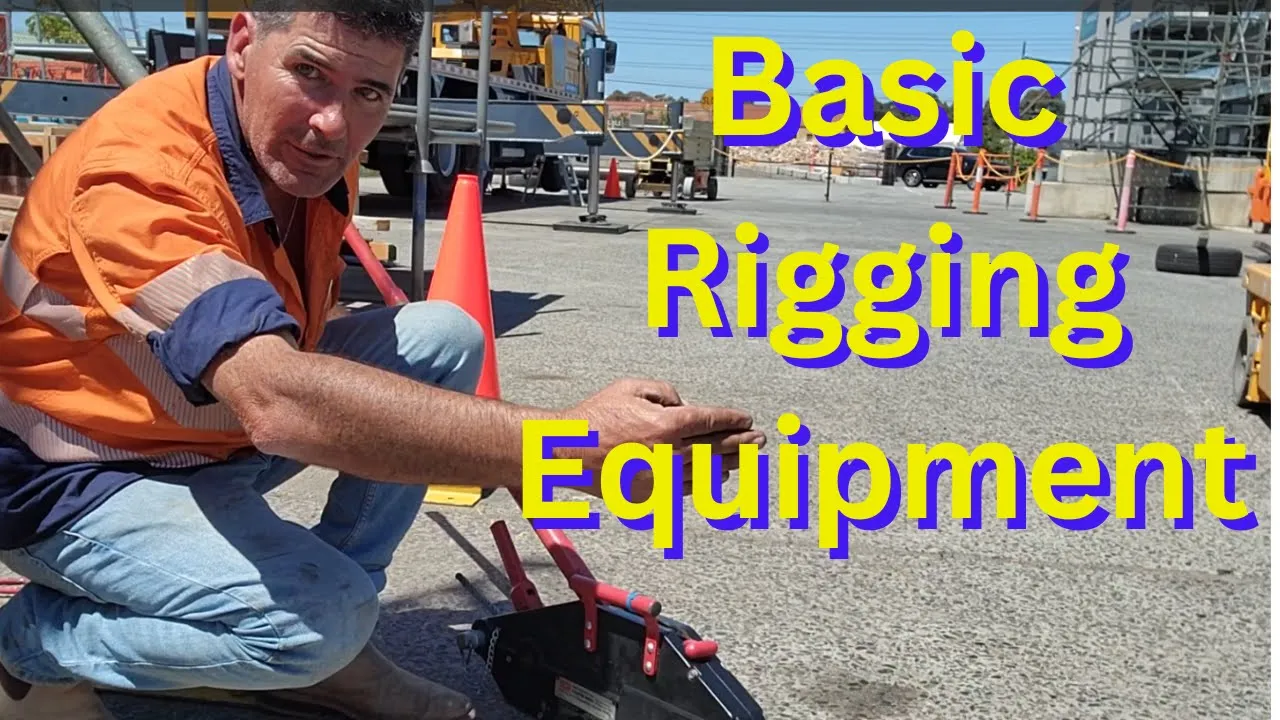
Basic rigging and slinging equipment
10.1K
In basic rigging, four essential tools serve different purposes: a turfor (hand-operated pulling device with two levers for releasing slack or creating tension) and camalong are used for horizontal pulling tasks, while a chain block is specifically designed for vertical lifting in areas with limited headroom; a beam clamp secures these tools to structural steel beams. The key distinction is that chain blocks should never be used horizontally as they will jam with dirt and grit, whereas turfor and camalong are ideal for horizontal pulling operations.
Click to watch →

Rigging Flight Control Cables
115.2K
This comprehensive process covers installing the control stick assembly by bolting it in place, attaching the connecting tube, and pushing bearings into the elevator bell crank. The assembly connects via rod end bearings and a push rod. Turnbuckles attach to the bell crank with bushings and washers as spacers. Fairleads guide cables, and pulleys redirect tension. Cable length is measured with mason line and cut with a cold chisel. Nico press sleeves create cable eyes with three crimps checked by go/no-go gauge. Turnbuckles are set with five threads showing and rigged hand tight before final crimping.
Click to watch →

Negative rigging basics Pt.2 | Using a Rigging Block or Pulley | how-to Arborist climber tutorial
70.2K
In negative rigging for tree climbing, a rigging ring is the simplest method for most situations, while an arborist rigging block provides additional protection by distributing the load of a falling piece across the entire rope length, which is essential when working near rope capacity limits, catching larger pieces, or in tight spaces where the piece cannot run; the block's friction causes the short leg of the rope to experience more load than the long leg, and it can be attached midline for a clean knotless system.
Click to watch →

The Best-Selling Arborist Blocks UPDATED - TreeStuff Closer Look
8.6K
This comprehensive overview covers arborist rigging equipment including blocks and pulleys. Steel blocks (CMI) are robust, affordable, and bulletproof with screw lock closures and captive bushings, available from 1/4 inch to 1 inch. Aluminum side plate blocks are lighter with different WLL presentations. The CMI mini block (3/4 inch) has 51,000 lb MBS and 10,200 lb WLL with spring-loaded opening. Notch pulleys feature rounded edges, flared openings, and spring locks. DMM premium blocks use 10:1 safety factor (vs. 5:1 for others), with hollow axles for suspension or secondary control lines. Specialized pulleys like Petzl Spin L1D (one-way sheave for breaking power) and Rock Exotica Omni (three-step push button) enable mechanical advantage setups for 4:1 or 5:1 systems.
Click to watch →
Prerequisite Knowledge
- Concept 01Basic anatomy of an RC sailboat, including the mast, boom, rudder, and the functions of main and jib sheets.
- Concept 02Understanding the mechanical differences between standard positional servos and multi-turn winch (drum) servos.
- Concept 03Fundamental physics of friction, tension, and line routing, and how they affect mechanical efficiency in rigging.
- Concept 04Familiarity with basic rigging components such as fairleads, blocks (pulleys), and tensioning bows.
Subsequent Learning
- Step 01Configuring transmitter settings (endpoints, travel limits, and dual rates) to precisely calibrate sail trim angles.
- Step 02Implementing elastic/bungee-tensioned closed-loop systems to prevent line slack and drum overrides during sailing.
- Step 03Advanced sail trimming theory and tuning methods for varying wind conditions (light air vs. heavy weather).
- Step 04Routine maintenance, waterproofing techniques, and troubleshooting common winch servo failures like line binding or motor strain.
Servo Setup
Line Check
Servo Setup
0:01Playing Section
- 1
Place rudder servo low to avoid interference with winch servo.
- 2
Use a square ruler to align winch line exit precisely.
- 3
Route lines through eye screw and roller for smooth operation.
Sail Arm Servos as an Alternative to Drum Winches
While drum winch servos are a traditional choice for managing long sail sheets, many RC sailors advocate for the use of 'Sail Arm' (or lever arm) servos as a superior alternative. Instead of winding line around a drum, a sail arm system uses a high-torque servo with a long physical arm to pull the sheets directly. Proponents of sail arms argue they offer much faster response times and are virtually immune to the line overrides and tangles (jams) that plague drum winches when lines go slack. Additionally, sail arm setups are mechanically simpler to install and maintain. While they do require more physical swing space inside the hull and have limited travel compared to the multi-turn capability of drum winches, many hobbyists consider sail arms to be a more reliable and responsive choice for competitive racing and hassle-free sailing.
Deep Dive
Configuring transmitter settings (endpoints, travel limits, and dual rates) to precisely calibrate sail trim angles.

Futaba® Radio Programming 102
39.9K
This video teaches advanced Futaba radio programming concepts including endpoint settings (which control maximum servo throw at 100% for optimal resolution), limit settings (which prevent servo binding when multiple channels mix by reducing throw percentages like from 135% to 105%), and dual rate systems (which allow pilots to switch between full and reduced throw using switches, typically set at 100% and 80%). The function menu enables complex multi-surface aircraft setups like four-servo wings and dual rudder/elevator configurations by assigning multiple channels to move together.
Click to watch →

První let s RC letadlem, Video manuál pro začátečníky s RC letadlem
183.6K
Proper transmitter configuration is essential before flight. Verify that throttle increases with upward stick movement and decreases with downward movement—if reversed, adjust the reverse setting. The elevator controls pitch: moving the stick toward you should deflect the elevator upward, while moving away should deflect it downward. The rudder controls yaw: when looking in the direction of flight, left stick movement should deflect the rudder left and right stick movement should deflect it right. Set all trim values to neutral (centered) before flight. After setting trims, verify that all control surfaces are mechanically aligned horizontally with the fuselage by loosening and adjusting the corresponding linkage pins as needed.
Click to watch →
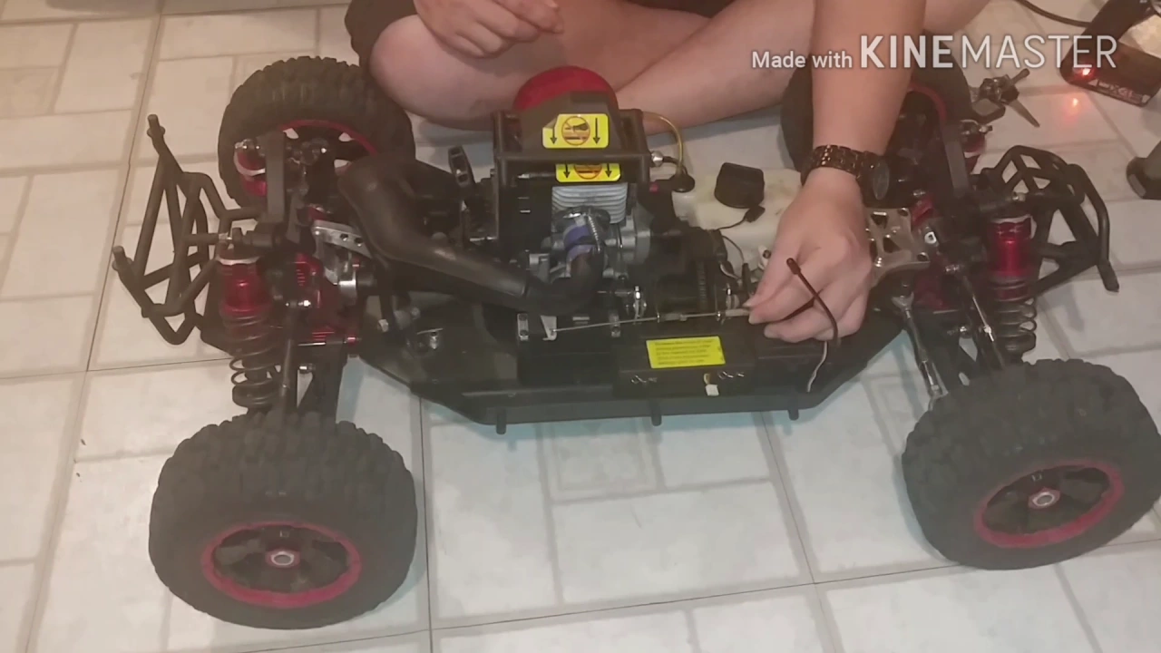
Travel/End point adjustment and D/R-Dual Rates/Steering Rates explained and demonstrated
5K
Dual rates is a transmitter feature that allows quick changes to steering sensitivity without physically adjusting endpoints. Endpoint adjustment is demonstrated by turning the endpoint knob: at 100%, wheels turn fully; at 50%, wheels turn less. This feature applies to steering, brakes, and throttle. For brakes, endpoint settings control how much braking force is applied before stopping. Proper endpoint settings prevent servo strain and ensure predictable vehicle control.
Click to watch →

Futaba T3PV radio transmitter full overview of features settings also see description binding videos
22.6K
The transmitter manages three primary channels with customizable control schemes. Dual rate allows limiting servo travel at full input to prevent oversteering or spinning out. Trim adjustments fine-tune servo position after initial setup, though excessive values (over 50%) indicate mechanical misalignment requiring linkage adjustments. Endpoint adjustment (EPA) defines maximum travel range, with values set before dual rate configuration. For ESC-equipped vehicles, proper calibration establishes neutral, full throttle, and brake positions, eliminating the need for excessive trim adjustments.
Click to watch →

Losi Mini-B MORE POWER/SPEED HIDDEN DUAL RATES
44K
Dual rates is a transmitter feature that reduces the maximum travel range of control surfaces. For steering, turn the stick fully left or right, then hold the minus button to reduce steering throw. For throttle, move the stick fully forward, then press down to reduce maximum speed. Throttle trim balances between reverse and forward, not simply raising or lowering throttle. To restore full control, hold the plus button on the respective channel. This feature is essential for beginners, allowing safe operation at speeds as low as 2-5 mph and preventing damage from crashes.
Click to watch →
Deep Dive
Implementing elastic/bungee-tensioned closed-loop systems to prevent line slack and drum overrides during sailing.
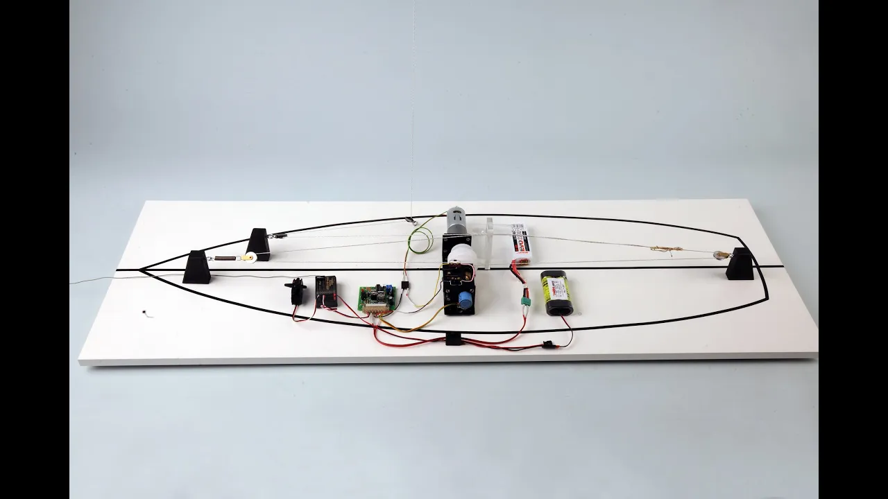
Segelwinde mit langem Schotweg für Großmodelle - Elektro-mechanische Funktionen proportional steuern
31.3K
Directly connecting the shroud to the drum causes problems during light winds when no tension exists, causing the line to slip and tangle. The correct approach uses two drums creating a continuous loop that maintains constant tension. One drum winds while the other unwinds, ensuring the loop always carries equal tension regardless of wind conditions, preventing dangerous tangling situations.
Click to watch →

#177 Sadly Real BAD STUFF happens in BLUE HOLES | Deans Blue Hole BAHAMAS | Sisu Leopard 45 Cat
4.7K
A bungee cord can be used to keep sails open and prevent them from touching each other, which causes chafing. The technique involves rigging a bungee cord to maintain sail separation, particularly when sailing downwind. This prevents the sails from flapping and chafing against each other while maintaining some sail shape and preventing complete depowering.
Click to watch →

How we actually sail Tally Ho - a technical gaff-rig walkthrough
203.5K
Before raising anchor to sail, the bobstay must be tensioned again. This involves letting off the tricing line and pulling in the tensioning line. Due to high friction in the dead eyes, hand tension alone is insufficient, so the capstan drum (or electric motor) is used to apply proper tension. One person operates the winch while another quickly secures the line on the cleat on the aft side of the stem, maintaining tension due to the friction in the dead eyes.
Click to watch →

Anatomy of a Winch: Basic parts and uses of sailing winches.
3K
Winches are essential mechanical devices on larger sailboats that manage the tremendous forces exerted by sails when wind increases. Unlike smaller boats that can handle sheets manually, larger vessels require winches for safe sail control. A standard winch comprises three key components: the slanted base that feeds line upward, the central drum where line wraps, and the top lip or self-tailor unit. The winch loads exclusively clockwise - spinning it reveals the correct direction as it locks in reverse. Proper line wrapping requires the line to travel from bottom to top without crossing, as crossed lines cause dangerous overrides. Wrapping quantity varies by conditions: light air needs 1-2 wraps, medium air requires 2-3 wraps, and heavy air demands 3-4 wraps. The self-tailor unit automatically grips the line through silver guides and top jaws, eliminating separate cleating needs. Critical safety protocols mandate never leaving winch handles inserted, as the spinning metal can cause severe injury. Always grip handles by the middle, fully seat them before operation, and store them properly when not in use.
Click to watch →
![Cape Horn Wind Vane Complete Installation — [Uma Gear Review]](https://i.ytimg.com/vi_webp/yaqW0EYF20I/maxresdefault.webp)
Cape Horn Wind Vane Complete Installation — [Uma Gear Review]
179.6K
A piece of bungee cord passes through a nylon loop to help adjust the yaw while sailing downwind. This prevents over-correction by providing resistance that allows controlled movement. The bungee cord creates damping that smooths out the steering response, preventing excessive oscillation.
Click to watch →
Deep Dive
Advanced sail trimming theory and tuning methods for varying wind conditions (light air vs. heavy weather).

Learn to Sail - Basic Sail Trim # 2 - Scenarios
57.6K
Sail trim operates like a car's gear system: lower settings provide power and acceleration for light winds, while higher settings maintain speed in stronger winds. Sail trim settings depend on boat size, displacement, sail configuration, and keel design. In light winds, sailors create fuller sails with deeper draft by easing sheets until leech flutter occurs, then easing just enough to remove flutter. The main sheet adjusts sail shape and twist, while the boom vang controls twist. As wind strengthens, sailors reduce draft by increasing outhaul tension and move the sheet traveler forward. Sail tension indicators include vertical lines near the luff (too much tension) and horizontal lines (inadequate tension). Leech adjustment controls flutter: closing reduces flutter in light winds, while opening prevents excessive heeling in high winds.
Click to watch →
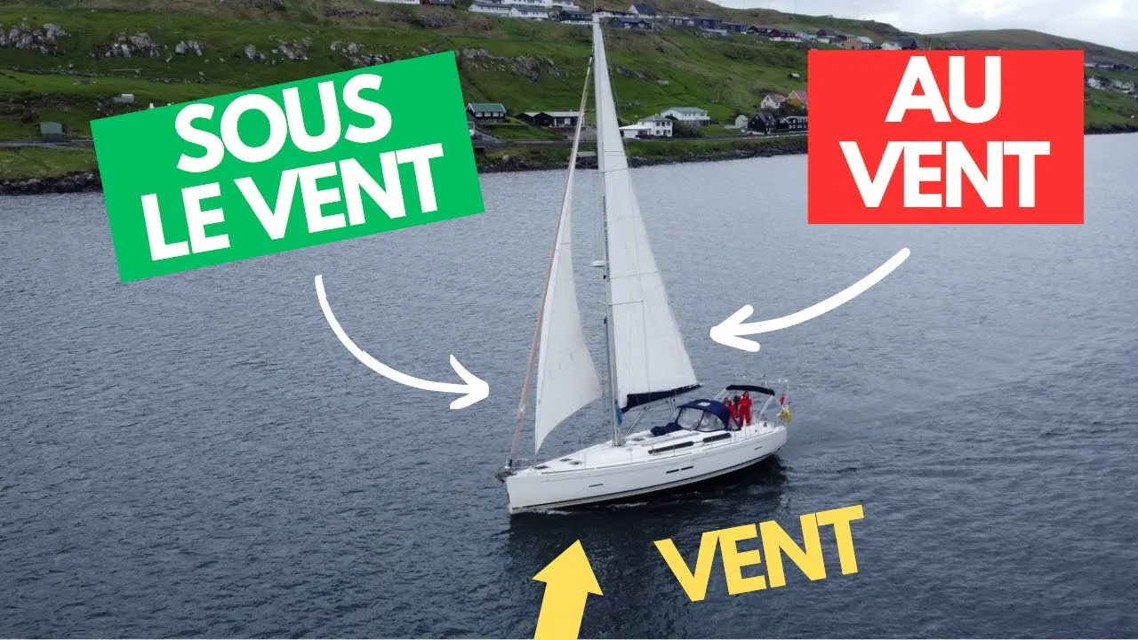
L’antisèche mouillée du prétendant barreur (20 mots)
45.2K
This section covers sail trim optimization using telltales (penons). Intrados telltales indicate the windward side, extrados indicate the leeward side. Proper trim shows both telltales floating horizontally. If intrados agitate, the sail needs 'bordé' (trimmed closer to wind) or the boat needs to 'abattre' (move away from wind). If extrados solo, the sail needs 'choqué' (tightened) or 'auffé' (trimmed closer to wind). Wind behavior is described as 'refuser' (refusing - wind coming from front, intrados drop) or 'adonner' (giving - wind shifting to allow passage, extrados drop). These skills enable sailors to maintain optimal sail trim and boat performance.
Click to watch →
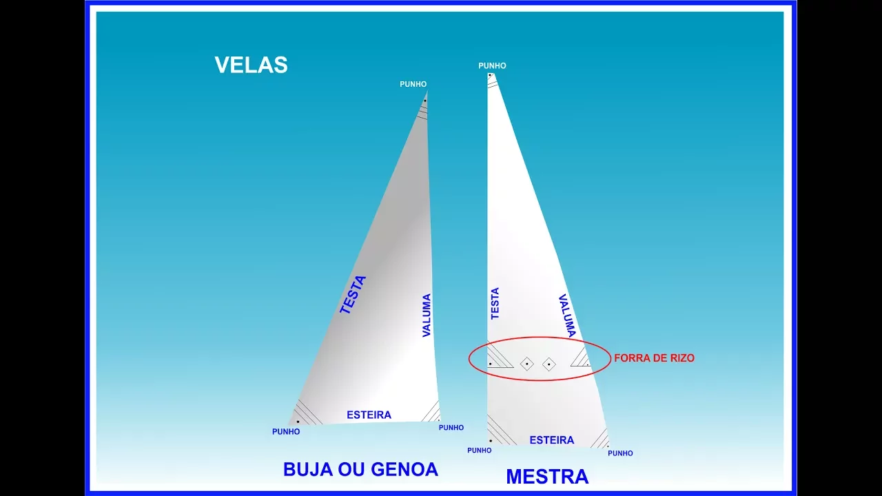
Aula 7: vento aparente e trimagem das velas
51.9K
Apparent wind is the wind experienced relative to a boat's movement, combining the true wind with the wind created by the boat's forward motion; it becomes perceptible at speeds of 7-8 knots and above. Sail trim involves adjusting sail shape (flatter in strong winds, fuller in light winds) and positioning (caçar/folgar) to optimize boat performance, with proper trim indicated when the leech of the sail begins to flap slightly.
Click to watch →

COMO AJUSTAR AS VELAS DO VELEIRO
40.9K
Sailing requires understanding four wind positions: contravento (into wind), través (wind from side), aleta (diagonal from stern), and popa (wind from behind). In contravento, sails must be fully trimmed (caçada) to prevent planing; exceeding the limit enters the 'zona morta' where the boat stops. Use zigue-zague maneuvers to change direction safely. In través, open sails to half their extent for optimal aerodynamics. In aleta, the boat moves with the wind, reducing wind sensation. In popa, the boat moves fastest but requires careful rudder control as the front sail tends to change sides.
Click to watch →

Life at Sea on our Tricky Sail to the next Atoll (Calico Skies Sailing, Ep 241)
18.7K
Sailboat performance varies significantly with wind conditions and sail configurations. When winds drop to 16 knots, boats may need to motor to maintain passage speed. Different sail setups work better at different wind speeds—double headsails at higher speeds, main and jib at lower speeds. Sailors must constantly adjust sail configurations based on wind angle and speed, with some configurations working well at 20 knots but becoming less effective as winds decrease.
Click to watch →
Deep Dive
Routine maintenance, waterproofing techniques, and troubleshooting common winch servo failures like line binding or motor strain.

RC ADVENTURES - Waterproofing RC, CHEAP! Example Model: Axial SCX10 RC Truck - Tutorial
541.2K
Waterproofing winches focuses on protecting the internal circuit board rather than the brushed motor. Apply plastidip directly to the circuit board to create a waterproof seal. While effective, motors will eventually seize due to water exposure over time. For transmissions, apply marine grease to all bearing surfaces and around gears using small blobs. Work grease carefully to avoid over-greasing, which causes binding issues during operation. Regular reapplication maintains protection. Marine grease creates a protective barrier against water while allowing components to move freely.
Click to watch →
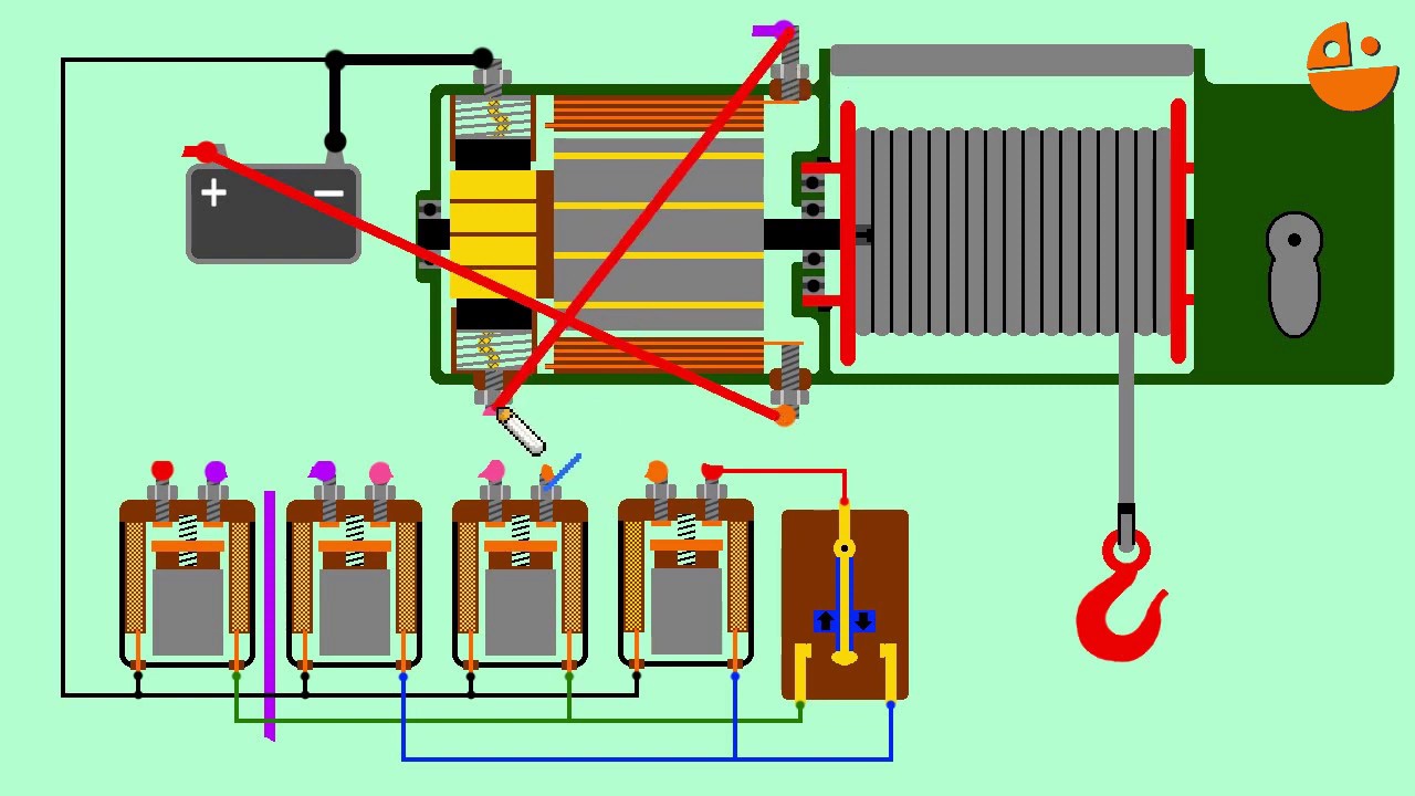
Как отремонтировать лебедку, поиск неисправностей автолебедки.
23.8K
This section covers the primary failure modes affecting winch operation. Moisture ingress causes 50% of failures, leading to corrosion that prevents rotor engagement with the electromagnet. Electrical failures include stator winding damage causing short circuits, commutator segment burnout, and brush contact loss. Relay failures involve contact welding and liquid intrusion. Control panel issues include connector oxidation and cable damage. Switch failures include melted housings and burnt contacts. Wiring problems occur in crimped terminals where oxidation develops. Battery terminal corrosion and poor ground connections are critical issues. Before electrical testing, manually rotate the winch drum to check for mechanical binding, as the drum should rotate freely when the brake is released.
Click to watch →
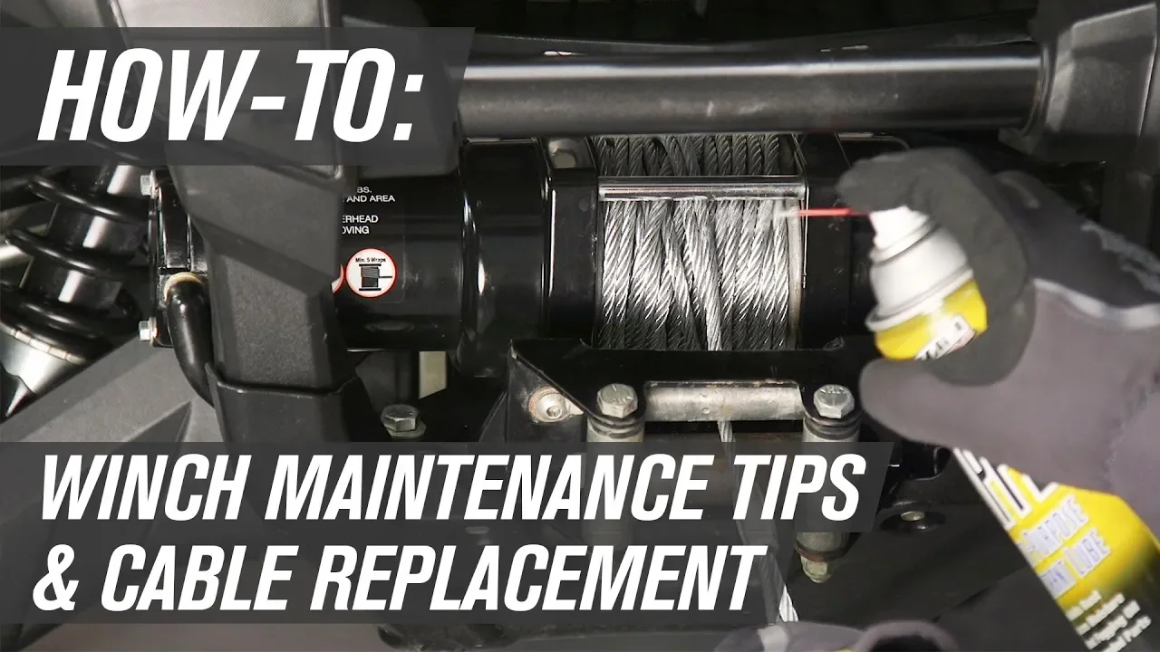
ATV & UTV Winch Maintenance Tips & Cable Replacement
108.1K
Regular winch maintenance includes lubricating connectors with dielectric grease, keeping the winch clean, testing the freewheeling function, and lubricating fairlead rollers; for cable maintenance, apply lubricant to prevent corrosion and always rewind the cable completely after each use to prevent binding and kinks; to replace a cable with synthetic rope, remove the hook by extracting the cotter pin, disengage the winch, pull out the cable, inspect the drum, feed the rope through the fairlead, wind it evenly with proper tension, and install a rubber bump stop before attaching the hook.
Click to watch →
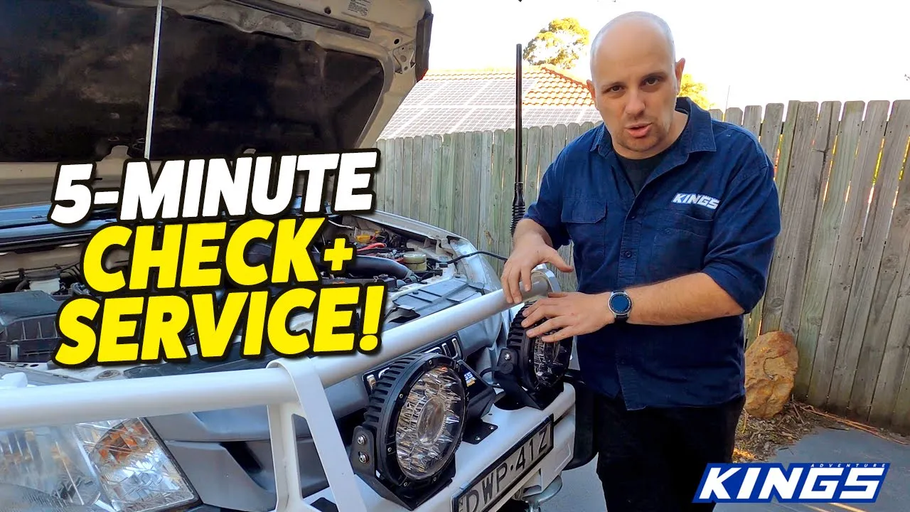
If Your Winch Stops Working! (12V 4x4 WINCH REPAIR + MAINTENANCE TIPS)
47.4K
This video demonstrates how to diagnose and repair common 12V 4x4 winch problems through systematic troubleshooting: first check the winch isolator switch and battery connections for proper contact and cleanliness, then inspect motor connections and control box terminals, and finally test the control box solenoids using a paperclip to bridge terminals; regular maintenance involves spooling the winch out and back in under tension after every four-wheel drive trip to prevent motor and gearbox seizing.
Click to watch →

Troubleshooting RC Electronics basics - Diagnose and fix it yourself
261.3K
For motor issues: if the ESC light indicates signal but motor doesn't turn, check ESC-to-motor connections, then try a different motor to rule out a burnt motor. For servo issues: test on a different radio channel; if the channel works for other components but not the servo, the servo or its connections are likely defective.
Click to watch →
Servo Setup
Line Check
Servo Setup
0:01- 1
Place rudder servo low to avoid interference with winch servo.
- 2
Use a square ruler to align winch line exit precisely.
- 3
Route lines through eye screw and roller for smooth operation.
Sail Arm Servos as an Alternative to Drum Winches
While drum winch servos are a traditional choice for managing long sail sheets, many RC sailors advocate for the use of 'Sail Arm' (or lever arm) servos as a superior alternative. Instead of winding line around a drum, a sail arm system uses a high-torque servo with a long physical arm to pull the sheets directly. Proponents of sail arms argue they offer much faster response times and are virtually immune to the line overrides and tangles (jams) that plague drum winches when lines go slack. Additionally, sail arm setups are mechanically simpler to install and maintain. While they do require more physical swing space inside the hull and have limited travel compared to the multi-turn capability of drum winches, many hobbyists consider sail arms to be a more reliable and responsive choice for competitive racing and hassle-free sailing.
Basic anatomy of an RC sailboat, including the mast, boom, rudder, and the functions of main and jib sheets.
Understanding the mechanical differences between standard positional servos and multi-turn winch (drum) servos.
Fundamental physics of friction, tension, and line routing, and how they affect mechanical efficiency in rigging.
Familiarity with basic rigging components such as fairleads, blocks (pulleys), and tensioning bows.
Configuring transmitter settings (endpoints, travel limits, and dual rates) to precisely calibrate sail trim angles.
Implementing elastic/bungee-tensioned closed-loop systems to prevent line slack and drum overrides during sailing.
Advanced sail trimming theory and tuning methods for varying wind conditions (light air vs. heavy weather).
Routine maintenance, waterproofing techniques, and troubleshooting common winch servo failures like line binding or motor strain.
6.8K views57likes3:04@venturesrcsOriginal Release: 2022-08-28
hello everyone welcome to the channel today i will show you again how to set a winch servo the right way to make it easy and smoothly so the first thing you have to do is to place the rather servo as low as possible into the hole as low as possible so it's not going to interfere with your winch servo which will be upper secondly you have to place as i'm doing right now a square ruler to put the right position of the exit of your winch line in this case is right here so once you set the winch line in the right position you can easily place all your lines in this case i use a double line one comes from the back of the boat gets in go to the eye screw and then goes out all the way to the back so it doesn't interfere with your rather servo doesn't engage and then it goes two lines as you can see here we have two lines one for the main cell one for the head cell here on the back i put a roller so these lines will move smoothly if they don't move mostly what is going to happen is that your head sail in this case is this line right here your head sail will stop moving and you will see that in the middle of the lake your head sail gets stuck in one position so this has to move as smooth as possible so then i show you how it moves it goes from this position all the way to this position so finally you find that the exit of the lines will come exactly in this position that is how you have to set your winch line for a successful sale and they you have to be careful that the lines and the arm they don't touch any area in this in the boat so okay enjoy your sailing make it fun and i see you on the next video bye bye
Up Next

6:00
Waterproofing RC Electronics at Home: A Hands-On Test of CorrosionX
@IRONCLADRC
7.6K views•2022-07-26

178:38
Whole Brain Architecture: First International Workshop 2024
@thewholebrainarchitecturei9784
640 views•2024-07-22

9:49
FastAPI vs Flask vs Django: Choosing the Right Python Web Framework
@TechWithTim
302.5K views•2024-05-26

1:42
Game of Thrones Opening Credits: A Cinematic Analysis
@gameofthrones
46.3M views•2011-04-18
Related Study Plans & Knowledge Roadmaps
Structured learning paths in General & Interdisciplinary Studies
general-studies
Artificial Light: History, Tech & Human Impact
01The Pre-Electric Era: Fire, Oil, and Gas Lighting
02The Incandescent Revolution and Grid Electrification
03Gas Discharge and Fluorescent Illumination
+ 3 more learning modules
14h6 modules
Explore Roadmap
general-studies
Elevator Engineering: History, Physics & Cities
01From Hoists to Safety Brakes: The Dawn of Vertical Lift
02Hydraulic vs. Traction: The Engineering Physics of Elevators
03Modern Speed, Safety, and Algorithms
+ 2 more learning modules
12h5 modules
Explore Roadmap
general-studies
Rubber: Material Science, History & Geopolitics
01Origins of Natural Rubber & Mesoamerican History
02The Chemistry of Natural Rubber & Vulcanization
03The Geopolitics of the Rubber Boom & Colonization
+ 2 more learning modules
12h5 modules
Explore Roadmap
general-studies
Containerization: Evolution, Logistics & Trade
01Ancient Trade & Bulk Cargo: Amphorae to Barrels
02The Industrial Revolution & Cardboard Packaging
03The Containerization Revolution: Malcom McLean
+ 2 more learning modules
12h5 modules
Explore Roadmap