






















Wave optics studies light as waves, explaining phenomena like interference, diffraction, and polarization through principles such as Huygens' principle, where each wavefront point acts as a secondary source of spherical wavelets; Young's double-slit experiment demonstrates constructive and destructive interference producing fringe patterns with fringe width β = λD/d; diffraction occurs when light bends around obstacles comparable in size to its wavelength, with single-slit diffraction showing a central maximum flanked by secondary maxima; polarization describes transverse wave behavior where light can be filtered to vibrate in specific planes, with Malus' law (I = I₀cos²θ) governing intensity through polarizers.
Wave Optics Class 12 Physics | NCERT Full Chapter for NEET
Added:Basic Wave Mechanics: Understanding wave equations, amplitude, frequency, wavelength, and phase difference.
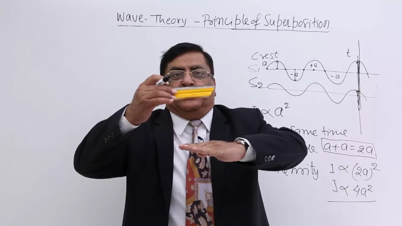
The Principle of Superposition: Knowing how two or more waves overlap and combine to form a resultant wave.
Ray Optics and Light Propagation: Familiarity with the laws of reflection, refraction, and Snell's Law.
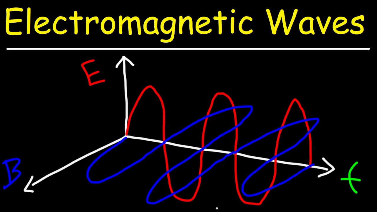
Electromagnetic Waves: Understanding that light is a transverse electromagnetic wave consisting of oscillating electric and magnetic fields.
Dual Nature of Radiation and Matter: Transitioning from wave theory to particle theory, exploring the photoelectric effect and de Broglie wavelength.
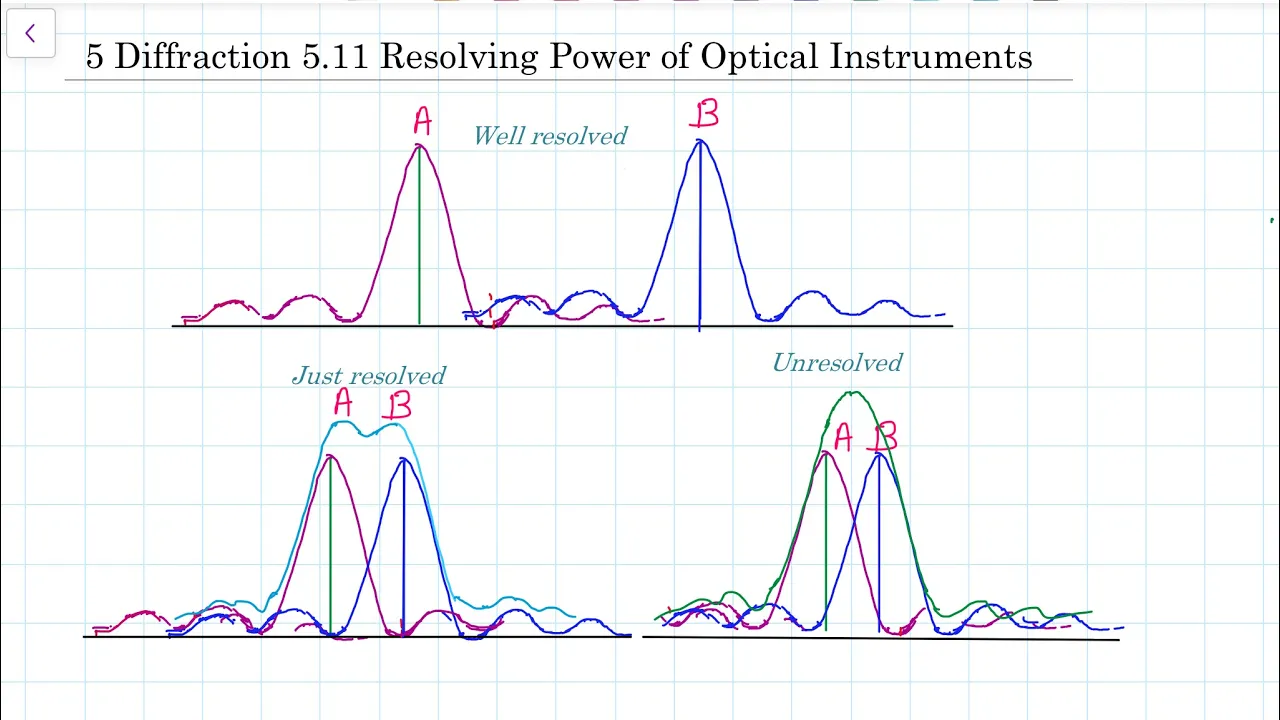
Resolving Power of Optical Instruments: Applying diffraction limits to calculate the resolution of microscopes and astronomical telescopes.
Real-world Applications of Polarization: Studying polarization by scattering/reflection, Brewster's Law, and how Polaroid sunglasses or LCD screens work.
Modern Interferometry: Exploring advanced setups like the Michelson Interferometer and its applications in precision measurements and gravitational wave detection.
334.2K views4.5Klikes1:48:40Original Release: 2017-11-13
a small pebble dropped in a pool of still water creates ripples on the surface these ripples form concentric circular rings around the source of disturbance and spread outward along the surface when these ripples reach a point on the surface of water the point starts oscillating up and down different points which are at the same distance from the source of the disturbance oscillate in fees that means all these points reach the crest or trough at the same time the locus of all such points having the same phase of oscillation is called a wavefront in case of water waves on the surface of water we observe circular wave runs each circular wavefront is a locus of all points having the same phase of oscillation the propagation of the waves can be understood by starting the propagation of wave fronts an outward normal drawn at any point on the wave front represents the direction of the wave at that point [Music] of energy we say that the energy of the wave propagates in a direction perpendicular to the wavefront [Music] the speed at which a wavefront travels is the speed of the wave waves on the surface of water are two-dimensional and hence the wave fronts are circular in shape but the waves from a source of sound or a source of light in a homogeneous medium spread in all directions and are three dimensional in nature now consider a point source of light placed in a homogeneous and isotropic medium emitting light waves in different directions if the medium is homogeneous the speed of light waves is the same throughout the medium and if it is isotropic it is the same in all directions the loci of all points which have the same amplitude and vibrate in the same phase forms a sphere with its center at the source of light hence a spherical wavefront is generated when a point light source is placed in a homogeneous medium at a large distance from the source these spherical wavefronts have large radii of curvature a small portion of a spherical wavefront at a very large distance from the source can be treated as a plane wave front in physical optics we visualize light as waves and wave fronts in ray optics we visualize light as rays a line drawn perpendicular to the wavefront in the direction of its propagation is treated as the ray of light in ray optics note that a wavefront is a surface of constant phase if a particular wavefront is a locus of points with maximum amplitude it continues to be like that as it propagates through the medium christiaan huygens proposed a geometrical method as the Huygens principle for finding the shape and location of a wavefront at some instant from the knowledge of the shape and location of the same wavefront at an earlier instance according to Huygens principle each point of a wavefront is a source of a secondary disturbance and generates spherical secondary wavelets which spread out in all directions with the speed of the wave in that medium if a tangential surf is common to all these secondary spherical wavefronts is drawn then it gives the new position of the wavefront at a later instant the surface envelopes all the secondary wavelets to understand Huygens principle let us now consider a primary wavefront a bee propagating in a homogeneous medium then according to the Huygens principle each point of a B acts as a source of secondary disturbance the secondary wavelets emanated from these points are spherical in shape and split in all directions at a speed equal to the speed of the wave if the speed of the wave is V then in time T the reaches of the spherical wavelets becomes VT she'll serve this common to all these fears in the forward direction gives the shape and location of the new wavefront after T seconds in the image the surface II dash B dash represents the location of the wavefront a B after T seconds the secondary wavelets must be directed backward as well as forward from the secondary point sources if this would be correct we would get a surface such as a double dash B Double Dash as a back wave but experimental results do not show the presence of any such back wave in order to explain this Huygens proposed that the intensity of the spherical wavelets is not uniform in all directions but is maximum in the forward direction and zero in the backward direction hence the wavelets as well as the whole wave always propagate in the forward direction only now let us use Huygens principle to find the location and shape of a plane wave front at a later instant of time T let ABB a plane wave front at time T equal to zero according to the Huygens principle each point of a B acts as a source of secondary wavelets the radii of these spheres will be VT after T seconds - plane touching these small spheres in the forward direction gives the shape and location of the new wave front after T seconds when light waves are incident on an interface of two transparent media light gets partially refracted and partially reflected using the huge ins principle we can derive the laws of refraction and reflection and show that these loans are consistent with the wave nature of light that is first consider the refraction of light when it propagates from a rarer medium to a denser medium let s s - be the boundary of the - transparent media medium 1 and medium 2 in which the speeds of light are v1 and v2 respectively consider a plane wavefront a B in medium 1 that is propagating towards the interface SS - a normal to the wavefront in the direction of its propagation gives the direction of the wave let a - e be the direction of the wavefront a be in medium one if I is the angle between the wavefront a be in medium one and the interface SS - then the angle of incidence is also equal to I assume that at t is equal to 0 only point a of the wavefront a b is in contact with the interface SS - the shape and the location of the wavefront at any subsequent instant of time can be found by constructing secondary wavelets since point e is only interface SS - part of the secondary wavelet originated from this point refracts intermedium - and a part is reflected back into medium one if reflection at the interface is neglected hemispherical wave runs from point A propagate into medium to as the wavefront travels from medium one to medium 2 different points of the wavefront of incident only interface SS - at different instants of time if the point B is incident on the interface at C after T seconds then DC is equal to V 1 t since the speed of the light in medium to is v2 during the same period the secondary wavelets generated at Point a at time T is equal to zero we'll have formed a hemisphere of radius V 2 T secondary wavelets from different points on the interface form hemispheres of different radii in medium to if we construct a plain CD tangential to all these hemispherical secondary wavelets it would represent the refracted wavefront after T seconds note that edy being the radius of the hemispherical wavelet generated at a it is equal to Li 2t and the direction of AD is the direction of the refracted wave in medium 2 if the angle made by the reflected wave front CD with the interface SS - is R then it is same as the angle of reflection since angle BAC is equal to I from the triangle ABC we have sine I is equal to BC by AC similarly as the angle ACD is equal to our from the triangle ECD we have sine R is equal to ad by AC from these two equations we get sine i by sine R is equal to BC by ad on substituting the values of BC and AD in the equation and on further simplification we get sine I by sine R is equal to V 1 by V 2 let this be equation 1 we know that if light travels from a rarer medium to a denser medium it bends towards the normal and hence the angle of refraction are is less than the angle of incidence I from Equation 1 we can conclude that if R is less than I then V 2 must be less than V 1 does according to icons wave theory the speed of light in a denser medium is lesser than the speed of light in a rarer medium this is in contradiction to the assumptions made by Newton in his corpuscular theory of light in 1850 it was for called who first determined the speed of light experiment li and confirmed that the speed of light indeed is less in water than in air if C is the speed of light in vacuum then the refractive index of medium one n1 is equal to C by v1 and the refractive index of medium to n2 is equal to C by v2 therefore n 1 by n 2 is equal to V 2 by V 1 which can also be written as V 1 by V 2 is equal to n 2 by N 1 let this be equation 2 [Music] from equations 1 & 2 we can write sine I by sine R is equal to n2 by n1 this can also be written as N 1 sine I is equal to n 2 sine R this is Snell's law of refraction let us now consider the reflection of successive wave fronts at the interface SS - if the wave runs as shown represent crests of a wave then the distance between the two successive wave fronts in a medium is equal to the wavelength of light in the medium let the wavelength of light in medium one be lambda one and in medium to be lambda2 if the wavefront a B is considered the points a and B reach the points D and C at the same time as such the number of wave fronts between B and C is equal to the number of wave fronts between a and D therefore BC by a d is equal to lambda 1 by lambda 2 since BC is equal to V 1 T and AD is equal to V 2 T we have lambda 1 by lambda 2 is equal to V 1 by V 2 let this be equation 3 equation three implies that when a light wave refracts into a denser medium its wavelength as well as velocity decreases from equations 1 & 3 we can write sine I by sine odd is equal to lambda 1 by lambda 2 in case of light travelling from a denser medium to a rarer medium the diffraction of light is as shown using Huygens principle we can prove equation one for diffraction of light when it travels from a denser to a rarer medium since the speed of light in medium one is less than the speed of light in medium two the angle of incidence is also less than the angle of refraction [Music] if the angle of incidence eye is increased correspondingly the angle of refraction also increases for a particular angle of incidence known as critical angle the angle of refraction becomes 90 degrees and the wave grazes along the interface SS - if the angle of incidence is greater than the critical angle we will have total internal reflection as such the laws of refraction are consistent with the wave nature of light envy optics you have already studied about the laws of reflection now we shall study them again but with wave theory as the basis in order to prove the laws of reflection based on wave theory let us consider the reflection of a plane wavefront a - B - from a plane reflecting surface s s - let a B be the position of the wavefront when it just touches the reflecting surface at the instance T is equal to zero II - II gives the direction of propagation of the wave front and let us assume that the wave front is incident on the surface s s - at an angle I and the speed of the light in the given medium is V at T is equal to zero the point a is in contact with the surface SS - the secondary wavelets from points other than a have maximum intensity in the forward direction and zero intensity in the backward direction and thus they travel in the forward direction since the surface s s - is a reflecting surface the intensity of the secondary wavelets from a is maximum in the backward direction and minimum in the forward direction thus we can say that the secondary wavelets from a propagate back into the same medium let us assume that after T seconds the point B of the wavefront a B is incident on the surface s s - at Point C then BC is equal to VT during the same period the hemispherical secondary wavelet from II would also have attained a radius equal to VT hence a hemisphere with its Center at E and radius equal to V T represents the secondary wavelet that originated from a at time T is equal to zero if the surface such as seee tangential to the hemispherical wavefront and passing through the point c is constructed then C II would represent the reflected wave front ayyyy is the radius of the hemispherical wavelet generated at the point a and is equal to VT that means AE is equal to BC is equal to VT the angle that the reflected wave front seee mix with the surface SS - is the angle of reflection let it be Peter the two triangles AEC and ABC are right-angled triangles with a common site AC and with two other equal signs AE and BC therefore these two triangles are congruent [Music] hence the angle BAC is equal to the angle EC a this means the angle of incidence I is equal to the angle of reflection theta this is the law of reflection let us now understand the behavior of a plane wave front as it undergoes refraction through a prism as well as through a lens consider a plane wavefront a be passing through a glass prism as the wavefront EB passes through the prism the point e travels for longer distances in the glass than the point B since the speed of light weight is less in glass point II and the lower portion of the wave front passing through the prism are delete and as a result there is a tilt and the emerging wavefront a - B - when a plain wave front is refracted through a convex lens it becomes a converging spherical wavefront and converges at a point on the principle focus on the other hand if a plain wave front is refracted through a concave lens we get a diverging spherical wavefront if a plane wave is incident on a concave mirror upon reflection it becomes a converging spherical wave note that the time taken from a point on the object to the corresponding point on the image is the same measured along anyway observe the image formation of a point object placed before a convex lens although the way going through the center traverses a shorter path because of the slower speed in glass the time taken is same for rays traveling near the edge of the lens that is now discuss about the Doppler effect of light the apparent change in the frequency of light due to the relative motion between the source of light and the observer is called the Doppler effect you have already studied about the Doppler effect related to sound waves that is recollect the expressions we had derived for the Doppler effect of sound waves let's VSB the city of the sauce VOB the velocity of the observer both these velocities are relative to the medium in which they propagate and act along the line joining them also let knew not be the frequency of sound when the source and the observer are stationary new be the frequency when the source is in motion and the observer is at rest and new - be the frequency when the observer is in motion and the source is at rest then as for the Doppler effect for sound waves we have nu is equal to nu naught into 1 minus vs by V and new dash is equal to nu naught into 1 plus V or by V than be equations 1 & 2 thus in the case of sound waves since the velocities of the source and the observer are relative to the medium in which they propagate the effect on the frequency when the source moves away from the observer is different from when the observer moves away from the soules but this is not true in the case of Doppler effect for lightweights that is now understand the reason for this we know that the speed of an electromagnetic wave is same in any inertial frame of reference as a consequence for the purpose of Doppler effect of light a source of light moving through a medium in which the observer is at rest and an observer moving through that medium with the source at rest are physically identical situations hence we cannot use equations 1 & 2 in case of light waves the expression for the Doppler effect of light is predicted based on the theory of relativity expression is new is equal to new not into square root of C minus V by C plus 3 let this be equation three in this expression C is the speed of light in vacuum and V is the velocity of the source with respect to the observer viii is taken along the line joining the source and the observer the is positive when the source moves away from the observer and is negative when the source approaches the observer equation three can be mathematically manipulated as shown to obtain equation four this V is very much less than C then v square by C square is much smaller than 1 in equation 4 and hence it can be neglected to obtain equation 5 when nu is equal to nu naught into 1 minus V by C equation five can be rewritten as new - new not all divided by nu naught is equal to minus of V by C if the change in the frequency nu minus nu naught is written as Delta Nu then the fractional change in the frequency Delta nu by nu naught is equal to minus V by C Doppler effect of light has an important bearing in astronomy when light emitted by stars is passed through prison a spectrum is obtained in the visible part of this spectrum lines of different wavelengths along with some intermediary doubt lines are present if a star moving away from us there is an apparent increase in the wavelengths due to the Doppler effect of light and hence the whole pattern of the spectrum gets shifted towards longer wavelengths this is called the redshift our universe is continuously expanding astronomers have found an experimental proof focus in the redshift when a star is moving towards the observer there is an apparent decrease in the wavelength and the whole pattern of the spectrum gets shifted towards shorter wavelengths this is called the blue shift it is important to note that we can measure either the red shift or the blue shift very accurately by comparing the apparent wavelengths of the spectral lines with the known laboratory wavelengths when two waves reach a point in space at the same time the resultant displacement of the particle is given by the principle of superposition according to this principle the resultant displacement Y is the vector sum of the displacements y1 and y2 caused by two waves for coherent sources the waves generated by them will have the same amplitude same frequency and the phase difference between them is constant with respect to time the waves from coherent sources can interfere constructively or destructively [Music] if they interfere constructively at a point the individual displacements are numerically added to give the resultant displacement at that point when they interfere destructively at any point the individual displacements cancel each other and the resultant displacement at that point is the minimum you have already learned that for constructive interference the path difference must be equal to n lambda where lambda is the wavelength of light used and n is an integer in terms of the phase difference Phi the condition for the constructive interference is given by Phi is equal to 0 or plus or minus 2 pi or plus or minus 4 pi and so on for destructive interference either the path difference is equal to n plus half into lambda or the phase difference Phi is equal to plus o minus PI or plus or minus three pi and so on if sleight has wave nature it must legs a bit the phenomenon of interference when utens proposed the wave theory of light in 1678 there was no experimental proof for the interference of light subsequently in 18 not 1 Thomas Young demonstrated experimentally that light exhibits the phenomenon of interference let's study about Young's double-slit experiment take an opaque screen with a small pinhole s and place a monochromatic light source to the left of the screen now the pinhole s acts as a point source of light and propagates a spherical light waves to the right of the screen in all directions place another opaque screen with two very closely separated pinholes s1 and s2 to the right of the first screen when s1 and s2 are illuminated by the incident light from s they behave like two point sources of light and emit spherical waves to the right of the screen in fact s1 and s2 behave like virtual coherent sources of light these spherical waves from s 1 and s 2 can be made to interfere on the screen Gigi - placed in their path they form a series of bright and dark bands called interference fringes on the screen the bright bands correspond to constructive interference of light and dark bands correspond to destructive interference of light let's now study the interference pattern in detail let the distance between s1 and s2 be D the distance between the pinholes and the screen be D let a B be the perpendicular bisector of the line joining s1 and s2 and all be the point of intersection of the line and the screen we should now consider an arbitrary point P on the screen along a line GG - perpendicular to a b and passing through all let the distance Opie be ex light from the two sources s-one and s-two covers a distance of s1 p and s 2 p respectively to reach the point b this P corresponds to an interference Maxima then the path difference s to P minus s 1 P is equal to n-lambda [Music] let this be equation one on the other hand if B corresponds to an interference minima the path difference s to P minus s1 B is B equal to n plus half into lambda this be equation 2 here lambda is the wavelength of the light waves and n is an integer from the diagram as shown we can write that s to P Square is equal to d square plus X plus D by 2 whole square this is equal to D square plus X square plus d square by 4 plus XD similarly s1 p square is equal to d square plus X minus D by 2 whole square this is equal to D square plus X square plus d square by 4 minus XD therefore s 2 P Square minus s 1 P Square is equal to 2 XD this equation can also be written as s to P minus s 1 P is equal to 2x D by s 2 P plus s 1 P if capital D is much greater than the small D then we can zoom that s 2 p + s 1 P is approximately equal to 2 D then the path difference s to P minus s 1 P is equal to X into D by D let this be equation three from equations 1 & 3 [Music] the condition for point B to correspond to a bright band is X into D by D is equal to n-lambda [Music] or X is equal to n lambda D by D let this be equation for from equations 2 & 3 if X D by D is equal to n plus half into lambda then at point B we will have a dark fringe [Music] that is for dark fringe X is equal to n plus half into lambda into D by D [Music] let this be equation fine here n is equal to zero or plus or minus one or plus or minus two and so on [Music] the distance between the Centers of consecutive bright fringes or consecutive dark fringes is called the fringe width it's xn and xn plus-1 are the distances of the nth and n plus one bright or dark fringes from the central bright fringe then mathematically fringe width is equal to xn plus 1 minus xn from equation 4 the fringe width for a bright fringe can be written as lambda D by D from Equation five the fringe width for a dark fringe can also be written as lambda D by D hence the fringe width is the same for both the dark and bright fringes which means the dark and bright fringes are equally spaced if the fringe width is represented by beta then meat ax is equal to lambda D by D let this be equation 6 if the central point Oh is considered to be equidistant from both the sources s-one and s-two [Music] then s1 o is equal to s2 Oh [Music] this condition corresponds to n equal to zero condition for a bright fringe and hence we will have a bright spot at all now consider a line on the screen that passes through the point O and is perpendicular to both the lines a B and G G dash all the points on this line will be equidistant from s1 and s2 and hence we will have a bright central fringe along this line on either side of this central bright fringe we will have dark fringes if n is taken as 0 in the equation 5 we get the value of X equal to lambda D by 2 D [Music] likewise we will have alternate dark and bright fringes on either side of the central bright fringe note that a particular fringe corresponds to the locus of points with a constant path difference of s to P minus s 1 P matically locust of such points represent a hyperbola in sight the fringe pattern is strictly a hyperbola but for a large distance D the fringes will be very nearly straight lines a look at equation 6 once again the fringe width of an interference pattern is directly proportional to the wavelength of the interfering light waves the fringe width is maximum for red light and minimum for violet light the fringe width is inversely proportional to the distance D between the two sources s-one and s-two [Music] if we decrease the distance between the two sources the fringe width increases one more factor that influences the fringe pattern is the distance D between the Sosa's and the screen fringe width is directly proportional to D the actual separation between the fringes increases with the increase in distance of the screen from the two surfaces you note that the angular separation of the fringes remains constant as the value of D changes in the experiment discussed so far the original point source s is assumed to be on the perpendicular bisector of the line joining s 1 and s 2 and the central bright fringe occurs at all let's now observe the changes that take place in the interference pattern when point source s is shifted to a different position s - let point QB the midpoint of s 1 and s 2 and the angle s Q s - be fine the central bright fringe has now shifted from Oh - OH - the location of Oh - is such that all the three points s - q and OH - lie on a straight line and the angle sqs - is equal to angle oq o - so far we have observed the interference pattern formed by light waves emitted by two point sources all the fringes are straight lines even though the waves from the sources are spherical in shape if we add some more pairs of points surfaces horizontally each pair of points surfaces form the interference pattern at the same location hence the intensity of the bright fringes increases if the point sources are replaced with slits a similar straight interference pattern is formed with increased intensity what happens if we use two separate sources of light in place of s1 and s2 we don't observe any interference pattern on the screen this is because the light waves coming out from two independent sources of light will not have any fixed phase relationship hence they behave like incoherent light sources we do not observe any interference pattern even when we use an ordinary monochromatic light source to illuminate both s1 and s2 the atoms in an ordinary light source radiate light in an unsynchronized and random phrase relationship Camas young had overcome this problem by using light waves from a single slit to illuminate s1 and s2 in this setup any abrupt phase change in the soos will reflect an exactly similar phase changes in the light coming from s1 and s2 since laser light is coherent we observe interference pattern when s1 and s2 are illuminated by laser light let us consider a home setup where the music is audible from the adjacent room how can we hear sound when we cannot see the sound player this is because the sound waves Bend around the corners to reach our years this phenomenon of bending of waves around an obstacle in their path is known as diffraction all types of waves exhibit this phenomenon observe the diffraction of water waves at a narrow slit placed on its spot when the size of the slit is large the diffraction of water waves is quite negligible on the other hand when the size of the slit is very small we observe the diffraction of water waves very clearly the diffraction of waves depends on its wavelength if the size of the obstacle or the slit is of the order of the wavelength of incident waves then diffraction occurs this condition is also applicable to light waves the wavelength of visible light is in the range of 400 to 800 nanometer since the wavelength of visible light is much smaller than the dimensions of most of the obstacles it encounters we usually do not observe any diffraction if a screen is placed behind an opaque object light from the point source travels in a straight line and forms a shadow on the screen but if we look at the shadow closely we observe that no sharp boundary exists between the shadowed and the illuminated regions the illuminated region above the shadow of the object contains alternate bright and dark fringes because of diffraction of light and the pattern is called diffraction pattern that is now studied a fraction of light at a narrow slit place a monochromatic light source on one side and a screen on the other side of a narrow slit when the slit is illuminated by monochromatic light a diffraction pattern is formed on the screen the diffraction pattern consists of a central bright band which may be much broader than the width of the slit with alternate dark and bright bands on both sides the intensity of the fringes decreases very rapidly that is now analyzed the diffraction pattern mathematically we represent light as a beam of rays let the width of the slit Ln ba let the source of monochromatic light and the screen be very far away from the slit if the source is at a far away distance we can regard the incident light as plane wave fronts or alternatively the incident rays are parallel when a plain wave front is incident on the slit all the points of the plane wavefront are in phase according to huge ins principle every point of the wavefront acts as a source of secondary wavelets that spread out in all directions with the speed equal to the speed of propagation of the wave consequently we find so many microscopic point sources of light between L and n which produce secondary wavelets the diffraction fringes formed on the screen aren't you to the interference of these secondary wavelets produced by a large number of point sources since the screen is at a far away distance we can regard the race as parallel the diffraction formed in such conditions is known as some half a diffraction consider an arbitrary point P on the screen that is examined the conditions for point B to be a diffraction Maxima or a diffraction minima let em be the midpoint of the slit and a straight line passing through em be perpendicular to the plane of the slit which meets the screen at C with the line joining the points M and P make an angle theta with the normal MC consider light rays from two point sources L and n separated by a distance e reach the point P the path difference between these rays NP - L P is equal to NQ from triangle Ln Q n Q is equal to e sine theta but for small angles of theta sine theta is approximately equal to theta therefore the path difference is equal to II Peter now we shall analyze how contributions from large number of sources produce diffraction fringes on the screen that is first consider the central point see from the figure we can see that angle theta is zero for Point C that means waves from all the point sources reach C in phase and hence all paths differences are also zero which means waves from all parts of the slit contribute in phase at sea they interfere constructively introduce maximum intensity at sea now consider another point c1 on the screen such that a by 2 into theta is equal to plus or minus lambda by 2 let this be equation 1 imagine that the slit is divided into two equal halves l m and m in width width of a by 2 each consider the waves from the point sources located at L and M reaching the point c1 since these two sources are separated by a by 2 the path difference between them at the point c1 is equal to a by 2 theta let this be equation 2 from equations 1 and 2 we can conclude that the path difference between l and m at c1 is 1 half of the wavelength of the incident light hence the waves from L and M are out of phase and interfere destructively at c1 now if both the half slits L m and M n are considered for every wave passing through LM there is a corresponding wave passing through em n originating at a point a by 2 below the first one such that the two waves are out of phase at C 1 hence every wave arriving at C 1 from the upper half of the slit LM interference destructively with the one coming from the bottom half of the slit MN the intensity at C 1 is therefore 0 and C 1 corresponds to the first minimum of the diffraction pattern hence the condition for the first minima is Theta is equal to plus or minus lambda by a let this be equation 3 equation 3 implies that the central maxima can be made wider by making the slit narrower we can also divide the screen into four parts six parts and so on and using a similar argument we can show that the subsequent diffraction minima occur whenever theta is equal to plus or minus 2 lambda by ay plus or minus 3 lambda by a and so on so the general condition for a diffraction minima can be written as theta is equal to n lambda by ay where n is an integer let this be equation for in between two successive minima we will have secondary maxima we can find the location of the secondary Maxima for values of Peter approximately equal to n plus half into lambda by ay let this be equation five let us now verify the validity of equation 5 imagine that the screen is split into three equal parts off with a by 3 consider a point C naught approximately between C 1 and C 2 at an angle theta equal to 3 lambda by 2 E now consider two waves from the ends of the two top paths since the width of each part of the slit is a by three the path difference between them at C naught is equal to a by three into theta which in turn is equal to lambda by two hence these two waves interfere destructively at C not in the same way all the waves from the first part can interfere destructively with corresponding waves from the second part of the slit only the remaining one-third of the slit contributes to the intensity at sea not therefore the intensity of the secondary Maxima is much weaker than the intensities of the central maxima the intensity distribution due to diffraction of light is pashtun so far we assumed that the source and the screen are placed far away from the slit in such cases the intensity of the fringes on the screen is less if a converging lens is placed after the slit and the screen is placed at the focal point of the lens then the badly lead rays from the slit converge onto the screen to give a bright diffraction pattern note that the lens do not create any extra path difference in a parallel beam of light the wave traveling through a distance Delta X in a medium of refractive index n suffers the seen phase change as when it travels a distance n Delta X in vacuum this means that the path difference Delta X in a medium of refractive index in is equal to a path difference of N Delta X in vacuum the quantity N Delta X is known as the optical part of the light since the optical path of rays converging at any point on the screen is the same for all the Rays the lens do not create any extra path difference in a paddle beam let us now compare the diffraction fringes due to a single slit with the interference fringes formed in the double slit experiment we observe alternate bright and dark fringes in both the interference and the diffraction experiments the fringes in case of the interference experiment are due to superposition of waves from two sources whereas the diffraction pattern is a superposition of waves originating from each of the point sources on the single slit the interference pattern has a number of equally spaced bright and dark bands but the diffraction pattern has a wider central bright maximum the intensity of the successive Maxima decreases as we move away from the central maxima on either site in the case of diffraction the first minima is formed at an angle theta equal to plus or minus lambda by a whereas the condition of angular separation theta equal to plus or minus lambda by ay the response to the central maxima for two slit interference pattern with a equal to the separation between the slits now observe the intensities of the fringes formed in the single slit diffraction and the double slit interference experiments when it served closely double slit interference experiments we see a decrease in the intensity of the bright fringes as we move towards either side of the central maxima this happens because of the diffraction of light from each of the single slits in fact the baton is a superposition of a double slit interference pattern and a single slit diffraction from each slit the combined effects of diffraction and interference are as shown the diffraction pattern acts as an envelope and controls the regularly spaced interference pattern the number of interference fringes occurring in the broad diffraction peak depends on the ratio d by a where D is the slit separation and a is the width of each slit as the value of a decreases the diffraction pattern becomes flat and we observe a normal interference pattern imagine that while looking down the road at night you observe a distant light that becomes brighter and brighter and then it splits into two light sources when it comes closer you recognize it as the headlights of a car approaching you you weren't able to recognize it when the car was far away from you because of the limitation of the human eye and also of the optical instruments like telescope etc distinguishing two distinct objects that are very close to each other with a very small angular separation between them is called resolving two objects the minimum separation of two objects or points that can just be resolved by an optical instrument is called the limit of resolution of the instrument the smaller the limit of resolution the greater is the resolution or the resolving power of the instrument the resolving power of an eye or of any other optical instrument is limited by diffraction of light to understand this let us first study diffraction of light by a circular aperture consider your big board with a small circular aperture allow a plane wave front to be incident on it from one side and place a screen on the other side the parallel beam of light is diffracted by the circular aperture and we observe a diffraction pattern on the screen which consists of the central bright spot surrounded by alternate dark and bright rings the central bright spot is called the airy disk the intensities of the subsequent bright rings drop out very quickly as we move away from the central disc in fact 85% of light energy falls within the airy disk let us now describe the diffraction pattern mathematically let the time meter of the aperture be a the distance between the aperture and the screen BD and wavelength of the incident light be lambda if theta represents the angular reaches of each ring a complicated mathematical analysis of diffraction by a circular aperture shows that the first dark circle occurs at an angle Peter given by the condition sine theta is equal to 1.2 to lambda by a let this be equation 1 two small angles of Peter we know that both sine theta and tan theta are approximately equal to theta since the screen is at a distance D from the aperture where D is much greater than E [Music] which is the radius of the first dark ring odd is equal to D tan theta using equation 1 we can rewrite this equation as R is equal to 1 point 2 2 into lambda D by a did this be equation 2 the diffraction of light by a circular aperture is of great practical importance in various optical instruments such as telescopes lenses are used during image formation a lens allows only a light that is incident on its circular aperture thus a lens behaves like a circular aperture in an opaque screen let's consider a lens of focal length F with a screen at the focal plane of the lens is plain wave fronts of light from a distant point object are incident on the convergent lens then the image formed is a diffraction pattern consisting of a central bright disc encircling bright and dark rims this contradicts the assumption we made in ray optics in free optics we assumed that a converging lens focuses light from a distant point object to form a point image on its focal plane but if the fraction effects are taken into consideration the images in the form of the circular disc instead of a point if the diameter of the lens is e then using equation 2 the radius of the first dark ring r is equal to 1.2 2 into lambda F by a where F is the focal length of the converging lens let this be equation three as we know that a lens forms a disk image of a point source it limits the resolving to neighboring points imaged by a lens let s 1 and s 2 be to point sources of light placed before the converging lens due to diffraction the image is formed by the lens on the screen placed at the focal plane are two circular disks if the two sources are closely placed the disk images overlap each other and appear like a single disk these two images are said to be unresolved if the two sources s-one and s-two are moved apart the centers of their image tests also move apart for sufficient separation one can distinguish the presence of two disks in the pattern in this case we say that the two point sources are resolved two images are said to be just resolved it's the first minimum of one pattern coincides with the center of the other this is known as Rayleigh criterion this means that the radius of each bright disc should be equal to the separation between them but as per equation three the reaches of the central bright disc is equal to 1.2 to lambda F by a hence increasing the diameter of the lens decreases the r-value and as a consequence increases the resolving power of the lens the concept of a converging lens focusing light from an object at an infinite distance to form an image at the focal plane is applicable to a telescope the image so formed is not a point image but a diffraction pattern with a bright central disc of radius R given by equation three so in order to improve the resolving power of a telescope the objective of the telescope must be large enough in the case of a microscope we place the viewing object very close to the objective lens if s is the focal length of the objective lens then the object is placed slightly beyond s if a real image is formed at a distance of V then the magnification M is approximately equal to V by F let this be equation 4 if D is the diameter of the objective lens and to beta is the angle subtended by the objective lens at the focus of the microscope then from the figure dan beta is approximately equal to D by two by F therefore D by F is approximately equal to 2 tan beta let this be equation five if the first dark ring of the diffracted pattern is formed at an angle-theta then from equation 1 we have sine theta is equal to 1.2 2 into lambda by D for smaller angles of theta PETA is equal to 1.2 2 into lambda by D let this be equation six since the image is formed at a distance of Lee from the lens the radius of the central bright disc R is equal to V theta substituting the value of Peter from Equation 6 we get R is equal to V into 1.2 to lambda by D let this be equation seven if we have two objects separated by a small distance T before the objective of the microscope we observe to diffraction patterns corresponding to the two images as the separation between the two objects decreases the distance between the two images also decreases if the separation between the two images is less than R then the images are not result let diem be the minimum distance between the objects and art be the separation between them this M is the magnification then we can draw it R is equal to M into DM or diem is equal to R by M on substituting the value of our from equation 7 we get DM is equal to V into 1.2 to lambda by D whole / M since magnification M is equal to V by F f is equal to V by M therefore DM is equal to 1.2 2 into f lambda by D let this be equation eight from equations five and eight we get DM is equal to 1.2 to lambda by 2 tan beta for small angles of beta dan beta is equal to sine beta approximately therefore DM is equal to 1.2 to lambda by 2 sine beta let this be equation 9 if the medium between the objects and the lens has a refractive index of M then the expression for the minimum separation between the two objects DM is equal to 1.2 to lambda by 2 n sine beta let this be equation 10 the quantity and sine beta is called the numerical aperture of the objective of a microscope the resolving power of a microscope is defined as the reciprocal of the minimum separation between the two objects seen distinctly let us now compare the functioning of the two optical instruments the telescope and the microscope a telescope produces images of distant objects nearer to our eye therefore the objects which are not resolved at a far away distance can be resolved by looking at them through a telescope on the other hand the microscope magnifies objects and produces their larger images hence we can say that the telescope results whereas the microscope magnifies let us now find the limits for the validity of ray optics an aperture of size e illuminated by a padlet beam the fraks light into an angle equal to lambda by a approximately this is the angular size of the bright central maximum if Z is the distance of the screen from the slit in traveling a distance cent the diffracted beam acquires a width W that is approximately equal to set lambda by a the value of scent for which the spreading of the image due to the fraction is approximately equal to the size of the aperture day is called personal distance that means if W is equal to e then Z is equal to Z F hence ZF is approximately equal to a square by lambda [Music] hence for distances smaller than the Frenzel distance the spreading due to diffraction is also small but for distance is greater than setteth the spreading due to diffraction is considerably large and it dominates the assumptions of ray optics you wayde's are classified into either transverse or longitudinal waves depending on the relationship between the direction of displacement of the oscillating element and the direction of propagation if the displacement is along the direction of propagation of the wave then the wave is called a longitudinal wave whereas in the case of a transverse wheat the displacement is perpendicular to the direction of propagation of the wave polarization is a characteristic of all transverse waves for example waves on a stretched string are transverse in nature an element of the string oscillates about its equilibrium position perpendicular to the direction of wave propagation let us assume that the string is along the x-axis and it's free end is moved up and down along the y-axis the waves generated propagate along the x-axis and the displacement of any given element of the string is along the y axis such a wave is mathematically described by Y of xt is equal to a sine KX minus Omega T where e is the amplitude of the wave Omega is the angular frequency and K is the angular wave number the wavelength of the wave is lambda and is equal to 2 pi by K if a wave has only Y displacements and each point on the string moves in a straight line along the y axis then the wave said to be linearly polarized in the y-direction the propagation of the wave and the displacement of any element of the string always lies in the XY plane and hence it is also called a plane polarized wave and is referred to as XY polarized wave instead of moving the free end of the string up and down along the y-axis if we vibrate it along the z-axis then the displacement of any given element of the string is along the set axis the weave so generated is a Z polarized wave and is mathematically represented by Z of X T is equal to a sine KX minus Omega T it's the vibrations of the string are not confined to a given plane then the wave is an unpolarized wave pal it is handy about light waves light waves which are electromagnetic waves are transverse waves with the electric and the magnetic fields oscillating perpendicular to each other and to the direction of propagation in the case of light waves the direction of the electric field e is the direction of the polarization of the wave for example if E is always along the y-axis then the light wave is a Y polarized wave the plane determined by the e vector and the direction of propagation of the wave is called the plane of polarization of the wave if a field remains in a fixed direction then the wave is said to be linearly polarized or plane polarized the electromagnetic waves used for radio and TV transmission are plane polarized the light from sources like the Sun or an incandescent lightbulb do not show single plane polarization let us represent light using the e vector and it's propagation as shown the light from these sources is composed of many directions of the e vector distributed randomly around the direction of propagation of light this light is transverse but unpolarized an unpolarized light can be converted into a plane polarized light using Polaroids a Polaroid consists of a long chain of molecules aligned in a particular direction the components of the electric vector of the incident light which are in the direction of the aligned molecules get absorbed the direction perpendicular to the direction of aligned molecules is known as the past axis that means the pass axis of a Polaroid is the polarizing direction if an unpolarized light wave is incident on a Polaroid Loyd sheet transmits only that light which has its electric field vector vibrating badly to pass access and absorbs the light with Eve Ector vibrating at right angles to pass axes now consider a Polaroid sheet placed in the part of a plane polarized light the vector II shows the plane of vibration of the light incident on the Polaroid sheet if ey and E set are the components of e such that e Y is paddle to the past axis and II said is at right angles to it then only the ey component passes through the Polaroid sheet now allow light from an ordinary Souls to pass through the polaroid p1 and incident on the screen it is experimentally observed that the intensity of the polarized light transmitted through the sheet is half the intensity of the incident light rotating p1 has no effect on the transmitted being and transmitted intensity remains constant [Music] this can be explained as follows in an unpolarized light the direction of the e vector is randomly distributed around the propagation of light we can resolve these different vectors into components ey along the polarizing axis and isn't perpendicular to the polarizing axis if the intensity of the incident light is to I not then because of symmetry the intensity of light in the direction of the polarizing axis is I not and the intensity of light in the perpendicular direction is I not the polaroid allows only the ey component of the incident light to pass through it and hence the intensity of the transmitted light is half the intensity of the incident light let the intensity of the plane polarised light transmitted by the Polaroid p1b I not now place another Polaroid b2 between the first Polaroid and the screen in the part of the plane polarised light of intensity I not the intensity of the light falling on the screen depends on the orientation of the Polaroid ptoo if we start rotating the Polaroid P to the intensity of light incident on the screen reduces to nearly zero at one position and reaches its maximum when turned by 90 degrees from the position of zero intensity this can be understood by considering the orientations of the pass axes of the two Polaroids light passing through the Polaroid p1 gets polarized along its pass axis if the pulse axis of the Polaroid p2 is perpendicular to the past axis of the Polaroid p1 then no light is transmitted through the Polaroid p2 if the past axis of the Polaroid p2 is battlin to the pass axis of the Polaroid p1 then the entire light transmitted by the Polaroid p1 is also transmitted by the Polaroid - and hence the intensity is maximum if the pass axis of p1 makes an angle theta with the pass axis of p2 then the component of a paddle to the past axis of the Polaroid v2 is equal to e cos theta [Music] if p.m. is the amplitude of the light incident on the Polaroid p2 then its intensity I not is equal to en square the amplitude of the light emerging from the Polaroid t2 is then equal to e M cos theta and the intensity of light I emerging from p2 is equal to e M square cos square theta this can also be written as I is equal to I naught cos square theta this is known as Malou slaw Polaroid's are used in sunglasses windowpanes and also in cameras as filters to control the intensity of light that is first tally about polarization by scattering when light waves propagate in a medium they cause the electrons of the atoms of the medium to oscillate periodically in fact these oscillations of the electrons are in the direction of the electric field vector of the incident light we know that these oscillating electrons emit radiations the propagating wave is a result of the incident light and the radiations from the oscillating electrons consider the propagation of light in a transparent solid in such a case it is experimentally observed that the oscillating electrons radiate in the direction of propagation of light and hence the resultant wave has maximum intensity in the direction of the incident light therefore in case of solids the percentage of light scattered in the sideway direction is very less in a liquid or in a gas the sideway scattering is more when light propagates through them molecules of a liquid or a gas are usually separated by large distances and are bound together loosely the oscillating electrons of these molecules act independently and scatter more light sideways let us now consider the propagation of light through a gas assume that the propagation of light is along the x axis if the light is polarized in the XY plane then it makes the electrons of the gas molecules oscillate along the y axis but in case of transverse electromagnetic waves an oscillating electron does not radiate along the direction in which it oscillates hence the scattered light is in the xz-plane if the incident light is z polarized then the scattered light is in the Y explained now if an unpolarized light like the sun light propagates through the atmospheric air in the direction of the x axis different electrons of the air molecules oscillate in different directions and scatter light in different directions if we look at the light scattered sideways by gas molecules we can find that it is wholly or partially polarized if we consider an observer situated such that he's along the direction perpendicular to that of the propagation of light he observes the light to be completely polarized if the observer is situated along the direction of the z axis then the scattered light received by him is y polarized unpolarized light can also be totally or partially polarized by reflection consider an unpolarized light incident on an interface between two transparent media we know that it will be partially reflected into the first medium and partially reflected into the second medium we know that the plane of incidence is defined as the plane containing the incident light reflected light and the normal to the surface at the point of incidence it is experimental II observed that waves for which the e vector is perpendicular to the plane of incidence are reflected more strongly than those for which the e vector lies in the plane of incidence note that the e vector perpendicular to the plane of incidence is badly to the reflecting surface that means the reflected light is partially polarized in the direction perpendicular to the plane of incidence but for a particular angle of incidence known as the polarizing angle or the Brewster's angle the light for which he lies in the plane of incidence is not reflected at all but is completely reflected when light is incident at the polarizing angle the light for which the e vector is perpendicular to the plane of incidence is partially reflected and partially refracted the light for which the Elector lines in the plane of incidents is completely refracted into the second medium this means at the angle of incidence of the polarizing angle the reflected light is completely polarized perpendicular to the plane of incidence and the refracted light is partially polarized the intensity of the refracted light is much more than the intensity of the reflected light at the polarizing angle it is experimentally found that the reflected and the refracted light are at right angles if the polarizing angle is IB then the angle of reflection is also equal to IB let R be the angle of refraction from the figure ib+ 90 degrees plus R is equal to 180 degrees simplifying we get IB plus R is equal to 90 degrees let n1 be the refractive index of the first medium and n to be the refractive index of the second medium from Snell's law n° 1 sine IB is equal to n 2 sine R on combining these equations we get n 1 sine IB is equal to n 2 sine 90 minus IB be written as n2 by n1 is equal to sine IB by cos I be this means index of the second medium with respect to the first medium n to 1 is equal to tan i B this is known as the Brewster's law now use a good polarizer and completely remove all the light with its eave Ector perpendicular to the plane of incidence and allow it to fall on the interface at the Brewster's angle the light incident is completely transmitted and no light is reflected back into the medium one this means we can have total transmission of light interference is a phenomenon exhibited by all types of waves when identical waves from two sources overlap at a point in space the resultant wave intensity at that point can be greater or less than the intensity of either of the two waves this phenomenon is called interference here identical waves mean that the interfering waves have the same frequency and amplitude and the fries difference between them is constant with time when the resultant intensity is greater than the individual intensities the interference is said to be constructive if the resultant intensity is less than the individual intensity then the interference is destructive the phenomenon of interference can be explained on the basis of the superposition principle of waves according to the superposition principle of waves at a particular point in the medium the resultant displacement produced by a number of waves is the vector sum of the displacements produced by each of the waves let us understand the superposition principle and the interference of waves by considering the waves on the surface of still water two needles are placed above the water surface and meet to oscillate up and down periodically the two points s1 and s2 where the needles dip in the water act as the two sources of waves let B be a point on the surface of the water when waves generated at s1 reach the point P the point execute simple harmonic motion let y1 t be the displacement of the particle P due to waves from s 1 similarly when waves generated @s to reach the point P the displacement caused is given by Y to T if waves from both s1 and s2 reach the point P simultaneously the resultant displacement YT is given by the superposition principle as YT is equal to y1 t plus y2 T if waves produced by two sources have the same frequency and the phase difference between them does not change with time then such waves are said to be coherent and the two sources are called coherent sources let us assume that the two sources s-one and s-two are coherent and generate waves of amplitude e and angular frequency Omega consider a point P on the perpendicular bisector of the line joining the two sources s-one and s-two for such points s 1 P is equal to s 2 P since both the sources are at the same distance from P the waves reaching the point P are also in phase if the displacement produced at P due to the waves generated at the source s 1 is given by the equation y 1 is equal to a cos Omega T then the displacement at P due to the waves from s 2 can also be represented by y 2 is equal to a cos Omega T we know that the intensity of a wave is proportional to the square of its amplitude therefore if I not is the intensity produced by each of the sources then I notice proportional to a square the resultant displacement at B Y is equal to y1 plus y2 on substituting the values of y1 and y2 we get Y is equal to 2 a cos Omega T if I is the resultant intensity at PE then I is proportional to 4 a square in terms of intensity of individual waves I is equal to 4 I not the resultant intensity is four times the individual intensities hence we say that the two waves interfere constructively now consider a point Q such that s 2q minus s 1q is equal to two lambda where lambda is the wavelength of the waves here do lambda is the difference in the distance traveled by the waves to reach the point Q and is known as the path difference the waves from s2 will reach the point Q two cycles after the arrival of the waves from s 1 hence the path difference of two lambda is equal to a phase difference of 4 pi and the phase difference between the waves arriving at the point Q is equal to 4 pi if the displacement produced at the point Q due to the waves from s 1 is given by y1 is equal to a cos Omega T then the displacement produced by waves from s2 is represented by y2 is equal to a cos Omega t minus 4pi this is again equal to a cos Omega T the resultant displacement of Q Y is equal to y1 plus y2 on substituting the values of y1 and y2 we get Y is equal to 2 e cos Omega T and the intensity will be again equal to 4 I not you now let us consider another point R such that s - R - s 1 R is equal to minus 2 point 5 lambda since the path difference between the 2 waves reaching the point arm is 2.5 lambda the corresponding phase difference would be five by this means that the waves from s1 will arrive exactly two and a half cycles later than the waves from s2 does its the displacement produced at the point are due to the waves from the source s one is given by y1 is equal to a cos Omega T then the displacement due to the waves from s 2 will be y 2 is equal to a cos Omega T plus 5 pi which is equal to minus a cos Omega T the dudas placements y1 and y2 are out of phase if the net displacement at R is y then Y is equal to y1 plus y2 which is equal to zero [Music] hence the intensity at our is zero the dew waves are said to interfere destructively and this is known as destructive interference hence if waves are emitted by two coherent sources like s1 and s2 the general condition for constructive interference of these waves at a point P is the path difference between s1 P and s 2 P must be equal to end lambda where n is a positive integer let this be equation 1 constructive interference the resultant intensity is four times the individual intensities if the point P is such that the path difference between s 1 P and s 2 P is equal to n plus half into lambda where n is a positive integer then we will have destructive interference let this be equation 2 or destructive interference the resultant intensity is equal to zero since the two sources are coherent the resultant density at any point does not change with time if the two sources emit waves continuously constructive interference takes place at some points and destructive interference at other points that means points for which equation one is satisfied constructive interference takes place and the intensity in those points is full times the individual intensities what are the points where equation 2 is satisfied we have destructive interference and the intensity is zero the curves shown in the image form the locus of all points for which the path difference is an integral times the wavelength they denote all points on which constructive interference occurs in between these curves we have curves indicating the locus of all those points for which the path difference satisfies equation 2 that incase of interference the energy is redistributed arbitrary point II such that the paths difference between s1 e and s 2e does not satisfy the condition for either constructive interference or destructive interference let the phase difference between the displacements caused by the two waves at the point e b5 at the point II if the displacement caused by the waves produced at the source s1 is represented by y1 is equal to a cos Omega T then the displacement caused by the waves from s 2 will be y2 is equal to a cos Omega T plus Phi the resultant displacement at E will be y is equal to y1 plus y2 substitute the values of y1 and y2 in the above equation and on for the simplification we get y is equal to 2 e cos Phi by 2 into cos Omega T plus Phi by 2 the amplitude of the resultant displacement is equal to 2 a cos Phi by 2 therefore the intensity at E is I equal to 4 e square cos square Phi by 2 this can also be written as 4 I not coz square Phi by 2 did this be equation 3 equation 3 is a general expression which enables us to find the intensity at any point on the surface if the phase difference Phi is equal to zero or plus or minus two pi or plus or minus four pi and so on then cos PI by 2 is 1 and hence I is equal to 4 I not these points represent the interference Maxima this is the general condition for constructive interference in terms of phase difference it's the phase difference Phi is equal to plus or minus PI or plus or minus 3 PI and so on we will have destructive interference leading to zero intensity these points are the interference minima this represents the gentle condition for destructive interference in terms of phase difference if the two sources are coherent then the phase difference at any point does not change with time hence the interference pattern formed is stable if the phase difference Phi is not constant and changes with time then the interference pattern formed will also change with time the positions of maxima and minima will also change with time if these changes happen very rapidly we observe a time-averaged intensity distribution mathematically the average intensity is equal to 4 I not into the average of cos square Phi by 2 but we know that if Phi of T marries randomly with time the time averaged value of cos square Phi by two is equal to one by two in such cases the resultant intensity is given by I is equal to 2i not that means the two intensities are just added up so we need coherent sources to produce a stable interference pattern you [Music] [Applause] [Music] [Applause] [Music] [Applause] [Music] you
Up Next

15:00
Huygens Principle: Deriving Reflection & Refraction | Wave Optics
@Mahesh_Shenoy
241.2K views•2014-12-02

12:53
21cm Hyperfine Transition in Neutral Hydrogen: Radio Astronomy Basics
@AaronRobertParsons
12.4K views•2011-10-13

32:32
NMR Spin Physics I: Zeeman Effect, Resonance Condition & Larmor Frequency
@nptel-indianinstituteofsci8064
2.3K views•2024-01-17

27:14
Entropy and the Second Law of Thermodynamics Explained
@veritasium
27.5M views•2023-07-01
Related Study Plans & Knowledge Roadmaps
Structured learning paths in Physics
physics
Nuclear Physics (Decay, Fission & Reactors)
01Atomic Structure and the Binding Force
02Radioactive Decay and Half-Life
03Nuclear Fission Mechanics and Chain Reactions
+ 2 more learning modules
12h5 modules
Explore Roadmap
physics
Soft Matter (Polymers, Colloids & Rheology)
01Foundations of Soft Matter & Thermal Forces
02Polymer Physics and Macromolecules
03Colloids, Surfactants, and Self-Assembly
+ 2 more learning modules
38h5 modules
Explore Roadmap
physics
Analytical Mechanics: Lagrangian & Hamiltonian
01Mathematical Foundations: Calculus of Variations
02From Newtonian Mechanics to Constraint Dynamics
03The Principle of Least Action & Lagrangian Mechanics
+ 3 more learning modules
28h6 modules
Explore Roadmap
physics
General Relativity (Spacetime & Cosmology)
01Foundations of Relativity: Special Relativity
02The Geometry of Spacetime: Equivalence Principle & Curvature
03Einstein's Field Equations: The Mathematics of Gravity
+ 2 more learning modules
55h5 modules
Explore Roadmap